Dat73z
-
Posts
852 -
Joined
-
Last visited
-
Days Won
8
Content Type
Profiles
Forums
Blogs
Events
Gallery
Downloads
Store
Everything posted by Dat73z
-
Yup. Man I wish we still had those crazy chemicals from back in the day. When I worked at a shop more than a decade ago I remember we had some insane gasket remover we got from a truck/parts guy that literally dissolved everything. Awesome for headgasket prep and removing rtv. It's long gone though. Oh well, probaby better for the future.
-
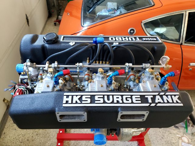
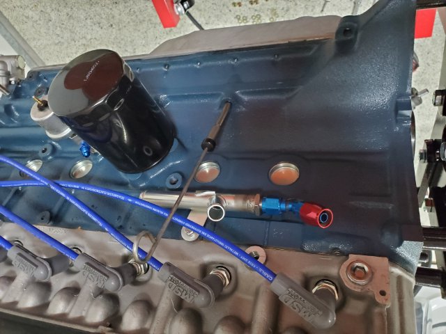
Got some parts back from powdercoat including some engine parts so started mocking things back up. For the vacuum log I'm going to try welding on a flat piece of AL on the bottom and slot some holes to bolt into the intake manifold. Maybe reserve the valve cover holes for a fuel rail. Still not 100% sure but got word on more parts delays this week so I've got some time to think about it.

-
Thanks grannyknot good direction. I visited 5 parts stores in my neighborhood and none of them had that or even carried it. I was honestly surprised and fortunate I have so many suppliers within a couple mi radius but have no idea why nobody carries this, maybe it's a CA thing. I'll try to order online but otherwise I'll try ball jars of gasoline or maybe the new reformulated aircraft stripper since I have a lot of odds and ends to prep.
-
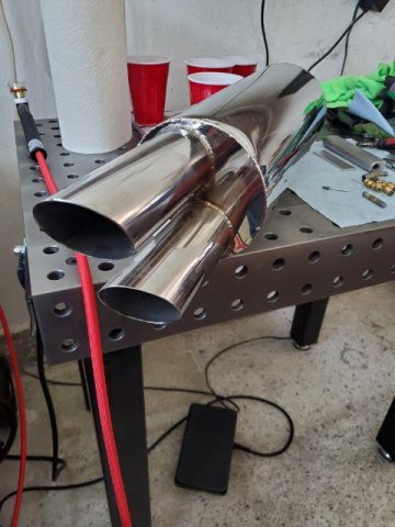
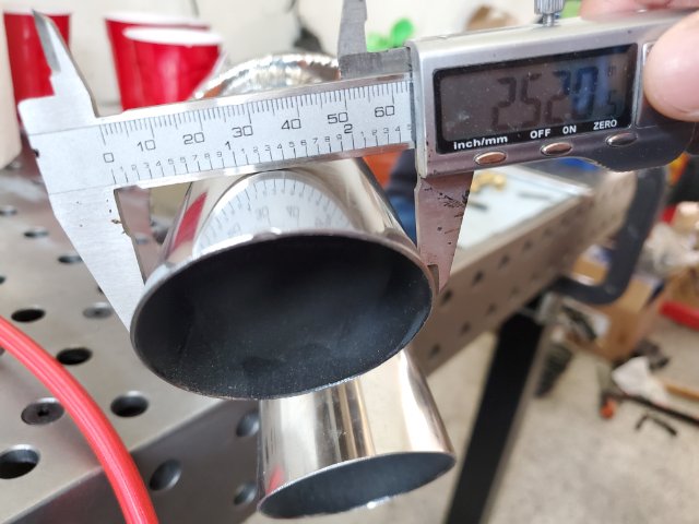
For those that are looking in 2021 Brute Fabrication produces a stainless option. I believe they are distributed by Godzilla Raceworks. They have some options but I was able to order a 3" inlet version. It has 2.5" tips.
-
A few years ago a younger me with more time probably would have went with a Miller tig and used it for many hours per week. This year I purchased a Primweld 225x for hobby purposes and have been pretty happy with it so far on carbon steel, SS and AL. Maybe use it a couple hours per week at most.
-
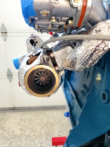
Thanks rossman. Yeah I noticed the boost was creeping on the dyno graphs so I ported out and smoothed the wg housing a bit more before heat shielding. The shield material is some inconel alloy. I'm planning to use the same material to shield the carbs, downpipe, and turbo cold side. Hopefully it'll all help with heat managment.
-
Got the manifold back from heat shielding and test fit. Mostly looks good but I'll need to trim one small area to clearance for a yoke washer. Waiting for a couple of parts to come back in so more chassis prep for this next week. I'm trying to set a goal for myself to have the motor back in the car by August so I can start fabricating the exhaust.
-
I have a lot of random brackets, fittings, nuts and bolts that have varying amounts of RTV pretty well stuck to them. Alot of these items are complex shapes so I can't simply skim them with a razor. Others I'd prefer not to wire wheel as to preserve surface finish. I've tried soaking and scrubbing with goo gone, acetone, denatured alcohol, brake parts cleaner with varying degrees of success and a lot of elbow grease. Any suggestions on the best way to remove rtv? After some research I was thinking some sealed glassware containers and gasoline to soak but I figured I'd solicit some opinions before giving that a shot. Thanks!
-
Thanks. Did you use the generic Valvoline synthetic moly grease? https://www.valvoline.com/our-products/grease-gear-oil/full-synthetic-grease After some more research it does sound like any off the shelf modern synthetic with moly would work well for CVs.
-
I'm looking for a 260z rear sway bar, the one that mounts in front of the diff. Probably an early one but I'm not sure the difference between the early 74 and later 74 260z bars. Please let me know if you've got one for sale. Thanks!
-
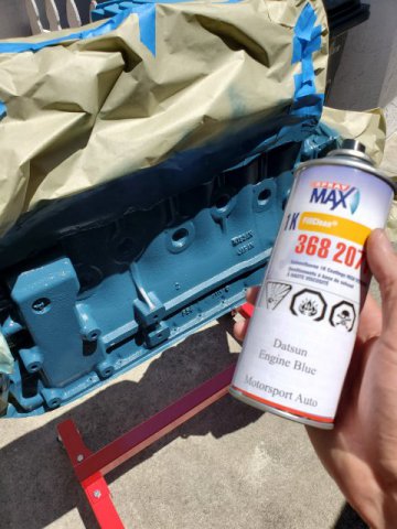
Had a day off from work and still waiting on parts so I decided to reshoot the block. When I got the motor back the paint was flaking in places, some areas which didn't get enough paint and a bunch of overspray everywhere. I cleaned up the overspray with acetone then fully degreased the block and hit it with some red sanding pad. Blew it off, degreased, taped and used a tack cloth. I used the MSA Datsun blue paint and really liked the way it laid down. Not sure how it'll hold up but at least the flaking areas won't bother me anymore.
-
And a picture of how the unknown brown stuff held up
-
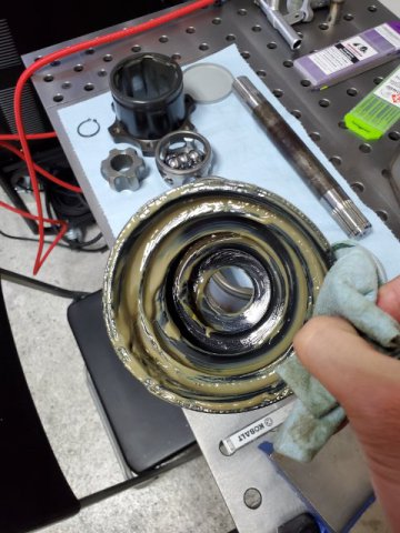
I'm currently in the process of rebuilding some Q45 CV axles. They were packed with some brown goop prior. I have some heavy duty Lucas green stuff which I had used on Troy Ermish CVs a few times before. Since I probably won't be cracking these open again for a few years and they don't have grease fittings I figured I'd ask for some opinions. Does anyone have any recommendations on CV grease? Any insight on what works well (or doesn't hold up) would be appreciated!
-
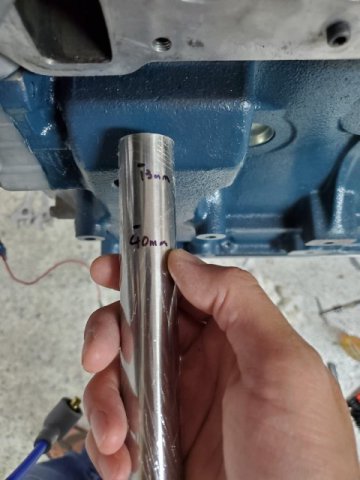
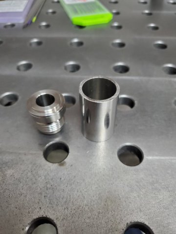
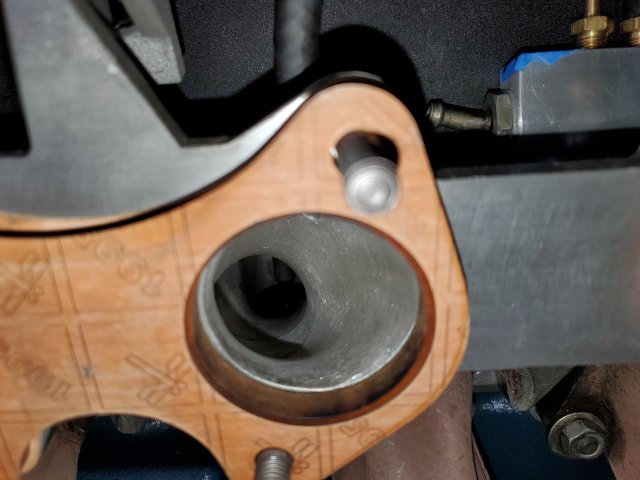
Waiting on parts to get back to wrap up the turbo motor so I started back on random bracket and parts fabrication. I couldn't find a crank vent tube so I made one with a 10AN fitting. It seems like ~25mm OD tube is a good interference fit for the block breather. I went with 40mm length on the tube portion but I don't think the length is a critical parameter.
-
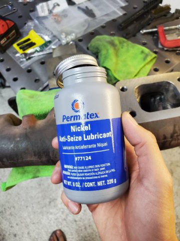
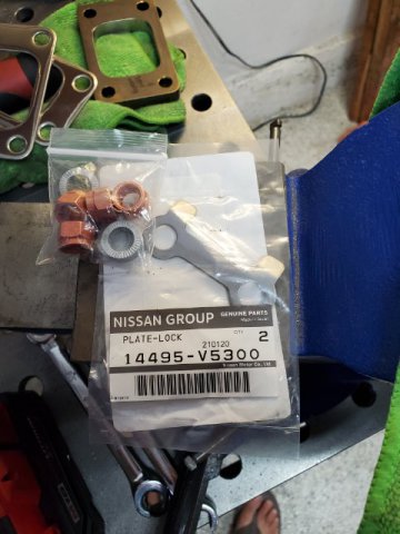
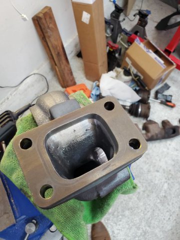
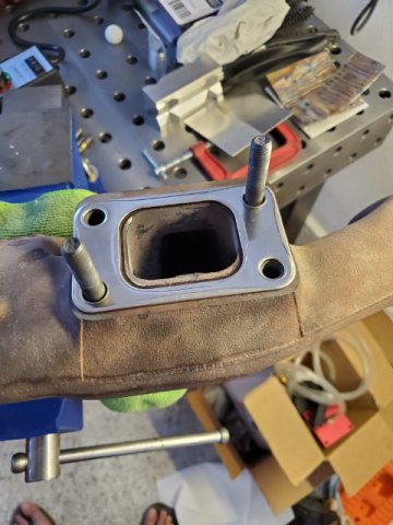
Dropped off the turbo manifold to have it resurfaced about a week and a half ago and took a break to work on some house projects. Just got the manifold back over the weekend so I threw it together and torqued everything. The machinist noted it was banana'd out on the head side and somehow the turbo side was warped as well so good thing he skimmed it all on the mill. Putting it together was really time consuming but I hope it'll be worth it and the hardware won't come loose with some heat cycles. I used nickel anti-seize, grade 8.8 studs, oem nissan plate locks, nordlock washers, and copper coated deformed head nuts. Sending it out tomorrow for inconel heat shielding.
-
Try your local radiator shop. I went to an oldschool place years ago to have my core rebuilt. Turned out they found a brand new Z heater core on the shelf from the 80s so I used that and kept my leaking one in case I ever needed a spare to re-core.
-
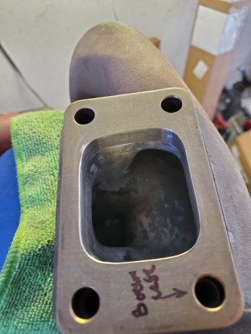
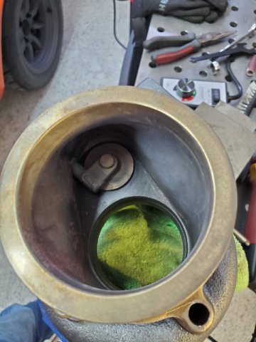
Wrapped up the porting. I didn't go crazy with it, but much better than when it ran on the dyno. The aftermarket t3 gaskets are much larger than the OE Nissan. Most of the time was spent on the manifold transition. Also opened the waste gate some more as it looked like there was some creep on the dyno graphs. Rebello noted they had to port the wastegate as boost was spiking to 14/15psi on the dyno towards redline and it made somewhere around 450hp on that run.
-
Where to Order Stainless Tubing and Vbands
Dat73z replied to Dat73z's topic in Fabrication / Welding
Thanks for all the responses guys. Good info and it sounds like Vibrant is in the lead. Has anyone tried Ace Race Parts / Ace Stainless? I'll try some local industrial warehouses too, but where I'm at in CA most things local are more expensive than ordering online including raw materials. Or at least that's been my experience with Argon and local metal suppliers which I'll still support since they do smaller walk-in orders but they mostly serve large commercial/industrial customers. I will be fabricating this myself in my garage. -
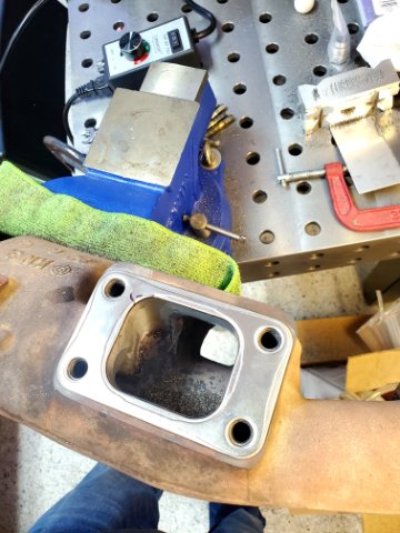
Started on finishing the porting job I started years ago. Will probably spend the next few evenings gasket matching and smoothing all the transitions. I'm gasket matching to the OEM Nissan gaskets.
-
Where to Order Stainless Tubing and Vbands
Dat73z replied to Dat73z's topic in Fabrication / Welding
Thanks Aydin, Do you have a preference or suggestion on Vband styles (ex: stepped/grooved lip) and vendors? I was doing some quick research over the weekend and there are a lot more options available now than even 5 years ago. -
I'm looking to order 2.5" and 3" stainless tubing and vbands for downpipe, exhaust, and charge piping. Does anyone have recommendations on where the best places to order are in 2021? Thanks!
-
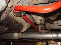
Had a few mins this evening to keep welding things. I had a couple of mild steel an6 bungs that I boxed up before moving but I'm still unpacking and couldn't find them but I did find a stainless an6 bung and some 309L filler wire so I started on the turbo coolant feed. The plan is to keep the heater and feed the turbo from where the SUs used to and return back at the thermostat housing. I used to cap these off with a rubber plug but the rubber never held up for more than a year of commuting before cracking and leaking coolant. Hopefully this holds better.
-
Quick weekend update. Welding up some brackets with the tig. Pulled the manifold off for some other prep and checked the porting. The transitions look pretty good, they're ported out to 47mm at the carbs, reducing to the Nissan gasket size at the head. Still waiting for some misc. parts to come in. This next couple of evenings I want to clean up some porting I did on the exhaust manifold before sending it out.
-
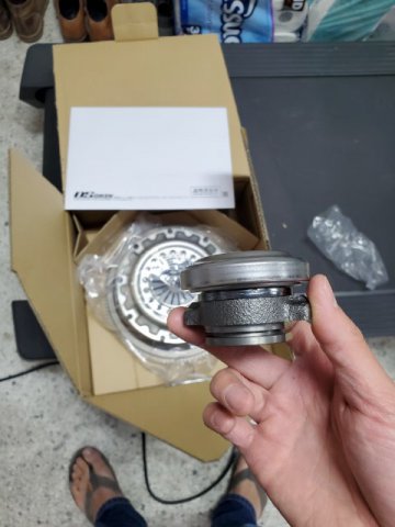
Last post on the driveline prep before going back into turbo stuff although I guess technically this is prepping the driveline for the turbo. Didn't find much info on the OSG damped twin or triple plate setups online so hopefully this is helpful to someone looking into it and the modifications required. The OSG throwout bearing collar is extremely short, and the stack height of the clutch assembly relatively tall.
-
Thanks Rossman. After thinking about it more and measuring angles I think another 45 or 30 would work with a short straight braided section in between. Just need to dig through my boxes and see if I can find one. Pretty sure I have one somewhere. I can clock my turbo a bit too to line up the angles better.