NewZed
-
Posts
6700 -
Joined
-
Last visited
-
Days Won
72
Content Type
Profiles
Forums
Blogs
Events
Gallery
Downloads
Store
Everything posted by NewZed
-
The 280Zs have an ECU controlled fuel enrichment when starting, described in the FSM. I assume that it adds injector open duration. Maybe the 300ZXs have the same feature.
-
I have a 280Z that was externally regulated so can't speak directly to a 260Z. But you now have two regulators in your charging circuit, the internal and the external. I'm not sure what happens when you do that. Have you checked voltage at the battery with the engine running? The easiest way for you (wiring challenged) might be the MSA adapter in the link I sent. It just plugs in to the plug that connects to the external regulator. All of the "re-wiring" is internal to the plug and the diode is inside. I sent you the wrong link, this one has just the adapter - http://www.thezstore.com/page/TZS/PROD/SRC19/12-4067 Or you could get the right alternator for an external regulator (but check your regulator also). Here is a link that has the 240Z alternator swap described, with the diode part number. It's not too complicated if you want to save a few dollars or don't want to wait for the MSA adapter. The alternator swap is about halfway down the page, Part 7 - http://datsunzgarage.com/engine/
-
Maybe you read about the MSA conversion kit - http://www.thezstore.com/page/TZS/PROD/12-4068 Did the engine run on before? And did you just swap an internally regulated alternator for an external, without rewiring? I'm not even sure what would happen if that was attempted. What year car and how did you get in to this situation?
-
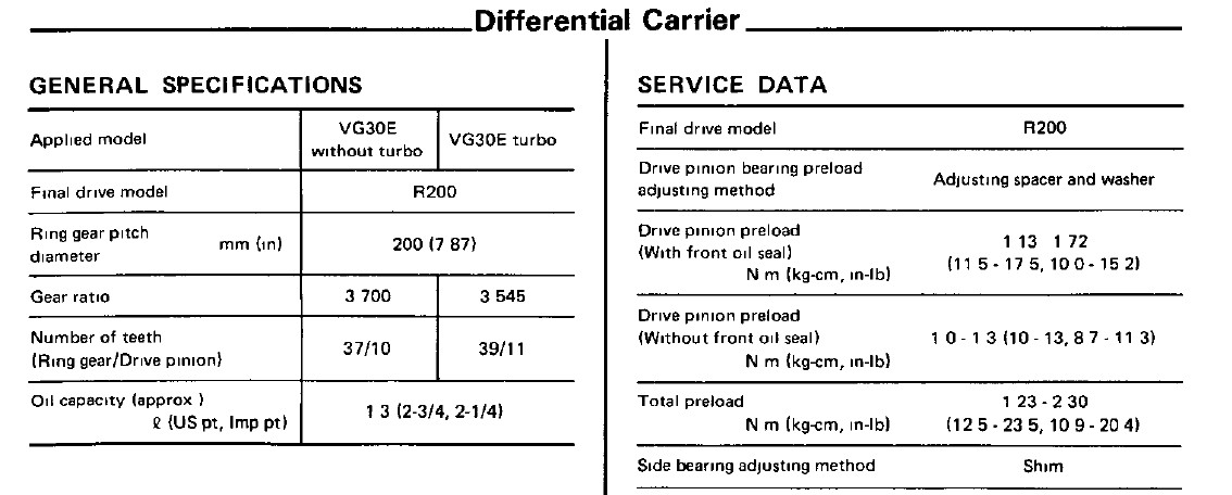
Here's the page from the 1987 FSM, it says the 1987 Turbo cars had 3.54 gears. I've heard that there are some errors in the FSMs. Can you tell where you got your information from?

-
You can hear them when the engine is turning over when you try to start it? They only cycle once per each engine revolution when the engine is turning over and the coil is firing. You might be hearing rocker/valve noise, it would be hard to distinguish injectors from all of the other noise with the starter engaged. Try grounding the coil (-) with the key On. The only noise then will be the snap of the spark when you tap to ground and the injectors all energizing every third tap. Or the screwdriver from injector to ear method while cranking the engine.
-
The injectors are opened by the ECU grounding the circuit to energize the injector solenoids. The injectors will always have power when the key is at On or Start. If you have power at the injectors then you need to look at the grounding circuit. The ECU gets it signal from a wire that runs from coil (-), through the tachometer and to Pin 1 at the ECU. Check continuity from coil (-) to Pin 1 at the ECU plug. The tachometer needs to be installed for your car to run.
-
The Auxiliary Air Regulator mounts on the two threaded holes of the aluminum piece. It will be a convenient thing to have working in Illinois. The valve with the hose at the end of it is the EGR piece.
-
No problem bud. Not sure what you mean by "under there" though. Make sure that your injectors are actually opening when the engine is turning over. Good luck.
-
You must be talking about the pintle caps. The general word seems to be that they don't significantly affect anything if broken. Broken caps certainly wouldn't keep the injectors from injecting. If the injectors have fuel pressure and they are energizing then fuel has to enter the head. Are you sure that the injectors are firing? People have been known to remove them, attach them to the fuel rail and place them in to containers, then crank the engine to verify fuel flow. It takes some work but if the engine runs with fuel added through a vacuum port or the throttle body then lack of fuel through the injectors is the obvious place to look. You can also turn the key to On, connect a jumper wire to the coil (-) and tap it to ground to hear the injectors fire. Credit to Tony D for describing the method, the basics of why are described in the FSM. Basically you're telling the ECU that the coil has fired three times and the engine has made one revolution. I just tried it to be sure it works. Three sharp taps to ground and you can hear the injector solenoids. I have a 76 but the electronics are essentially the same as your 78. The wire from coil (-) to the ECU Pin 1 runs through the tach by the way. So the 280Zs won't run without the tach installed.
-
diagnosing idle and low rpm acceleration issues
NewZed replied to StrokinIT's topic in Nissan L6 Forum
TJed is talking about the auxiliary air regulator. A good suggestion but sounds like you've checked it. Although the old hoses to the AAR can split leading to a vacuum leak. Another device that lets air past the throttle body is the BCDD. I have read that they can get stuck but have not experienced it myself. It's the weird looking thing attached to the bottom of the throttle body, with an electrical wire attached. It bypasses air based on RPM and intake vacuum. It's described in the Emissions section of the FSM. Boost Controlled Deceleration Device. The hesitation, stumble and backfire suggest a vacuum leak, leading to a lean condition. Air is getting in without moving the AFM vane. There are many places for small air leaks from the AC valve control canister and hoses to the PCV system. Most people suggest taking an unlit propane torch and blowing propane around the potential leak areas and listening for RPM change as it gets sucked in. I've never had to go that far so can't vouch for effectiveness. -
I know that it has a 14mm head on it. I believe it's the same thread as a transmission or starter mounting bolt. Remove a similar bolt (a transmission bolt should be right there close to the hole), try it in the hole and guess the depth.
-
Free time, curiosity and Google - http://www.hammondsplains.com/z/zworld/zenthusiasts/index.htm Contact at bottom but can't tell if it works.
-
What kind/brand of compression pressure tester are you using and are you using the adapter that some of them come with? The adapters add volume to the chamber and will give a low number. I got 180 without, and 120 with the adapter. I also got about 135 with a different tester, the kind with the rubber nozzle you hold against the spark plug hole. There is a lot of variability in testing tools.
-
Small backfire possibly due to afm?
NewZed replied to Naroko's topic in Trouble Shooting / General Engine
What year car the used AFM come from? How did you determine the old AFM was bad? How much time passed from when you replaced the AFM to when you determined you had a rich problem? If the car sat for a while there could be several reasons for rich running. Just trying to help with describing your situation. Details are good... -
Small backfire possibly due to afm?
NewZed replied to Naroko's topic in Trouble Shooting / General Engine
Do the numbers match on the AFMs? And have you tried putting the old one back on to make sure the new rich condition is from the new-old AFM? -
Question about 280z 5 speed tranny
NewZed replied to nissanboy85's topic in S30 Series - 240z, 260z, 280z
I have heard and read that the shift fork for 5th gear on the early five speeds is weak. Was your friend banging gears in his new ride? Does it still go in to reverse? There are several rubber boots and a leather cover that seal the cabin from the road. -
The most informative part of your post and title is "78 all oem Nissan 280z" in your sig. Seriously, you don't give much information. There is a high probability of shedding here. With your test light you should be able to at least tell what does have power. Battery to fusible links to ignition switch, etc. That's where I would begin. Track the power path until you find the break. Have you looked at the wiring diagrams? Does the ECU even control power to the ignition relay and starter? I'm not at my home computer, or I'd take a quick look. Download the FSM and look through the Engine Fuel and Body Electrical sections.
-
Car not starting 1983 280zx turbo
NewZed replied to WaiDai's topic in Trouble Shooting / General Engine
Have you measured fuel pressure? It's important. Also, you should probably avoid "adjusting" the Air flow Meter (AFM) until you can at least get a good idle. You'll just create more problems. You should check your CHTS resistance reading at the ECCS connector to see if it is working correctly. A broken circuit would tell the ECCS that the engine is cold and dump fuel accordingly. Checking at the connector tells you if the wiring and the sensor are all working correctly. The FSM has a good troubleshooting section in the EFEC section. Just jump ahead to Page 36. The AFM and CHTS are both described. -
help setting the timing when the heads don't match
NewZed replied to Mobious9's topic in S130 Series - 280ZX
If the camshaft and crankshaft are oriented correctly, you can't have a jumped tooth. You might be getting ahead of yourself. -
Pull the rubber boot off of the salve cylinder and look for fluid. It may be that the slave cylinder leaks more when it gets warm.
-
You have a boost control problem but did not say much about your boost controller. Some information on the "turbo upgrade" might also help.
-
I believe that the VLSD from the later 300ZX is a short nose diff, so you'll need something like the Modern Motorsports setup. You'll need a custom front mount and a few other not common parts. These two links describe what you're looking at - http://forums.hybridz.org/index.php/topic/49194-differential-cv-lsd-hp-torque-r160-r180-r200-r230-diff-mount/ http://www.modern-motorsports.com/catalog/product_info.php?products_id=74 The first link also describes the 300ZX CLSD, which is a long nose R200 and may be what you're looking for, but still is not a straight bolt-in. Apparently it only came in late 1987 to 1989 300ZXs. Not really sure where the transverse link comes in to the picture either, but I'm not an expert.
-
Give more details on what you're using and how it's wired, especially the distributor and HEI module. A pish-posh bunch of turbo parts could mean many things.
-
headache trouble shooting need desperate help!
NewZed replied to gmodz5000's topic in Trouble Shooting / General Engine
Your post could use some more details. "Tested everything" - how and what, and what were the results? "Hot wired" - how, what wires went where? Can you hot wire it and get it to start and run consistently? If so, you just need to focus on getting power to the starter and ignition circuit. Can't do much about the backfire until it runs again. -
This probably won't help with your overall problem, but NPN and PNP are types of transistors. The switch would have something to do with the expected input and output on that circuit. Transistors are used to fire your injectors and ignition coil by controlling current flow, so the switch setting would be important. Here's a Wikipedia link - http://en.wikipedia.org/wiki/Bipolar_junction_transistor Search NPN, PNP and transistor on Google if you want to dig in to it further. Good luck, the details are over my head...