NewZed
-
Posts
6700 -
Joined
-
Last visited
-
Days Won
72
Content Type
Profiles
Forums
Blogs
Events
Gallery
Downloads
Store
Everything posted by NewZed
-
Is it possible to log and view the actual injector open duration? This would show you how MS is controlling fuel. And is there a minimum duration for Megasquirt? With big injectors and high pressure, maybe you're at the minimum duration. Just guessing, I know a little data acquisition and control but don't have Megasquirt.
-
You can't post on a Tool Shed thread. But I do appreciate this shedding effort. Much better than words - http://forums.hybridz.org/index.php/topic/100294-best-rear-end-for-lt1-t56-combo/page__pid__940347 Thanks Ron.
-
help setting the timing when the heads don't match
NewZed replied to Mobious9's topic in S130 Series - 280ZX
It's probably possible to turn the engine over by hand, while holding the chain in place (get a helper), to bring the #1 piston to the top. If your timing mark is at zero and the rotor is pointing at the number one plug terminal in the cap then the block's #1 piston is at TDC, ready for ignition. Then turn the camshaft so that the #1 cylinder valves are both closed, put the head on and make the fine adjustment to the camshaft to line up the marks properly. The hardest part would be turning the engine over by hand while holding the chain on. -
At 6,0000 rpm, even ~1200 rpm, you should see around 14.8 volts at the battery. The older external regulators will even let up to ~15.5 through. Either your alternator or regulator is bad, or you have some wiring issues. Your assumption that the alt and battery were working correctly, back in Post #6 might be wrong. You might take the alt in to a parts store or auto shop to have it tested. If you had a bad battery, you might have damaged the alternator.
-
If your car wiring has been modified to use an internally regulated alternator (which might be why you can't find the regulator, because the PO did take it out) then the "upgraded" alternator that MSA offers my not be the right replacement, if you bought the upgraded alt for a '72 240Z. You might have created a short when you re-installed a non-regulated alternator, draining your battery. Either way, you should confirm that you have the right mix of parts. The wiring changes will be back where the voltage regulator should/would be, not at the alternator.
-
I didn't mean to contradict your post, it's vague grammar on my part. I was just showing the R180 possibility for 3.36 gears. They might be easier to find. Apparently the FSMs don't document everything that was possible on these cars.
-
Here's a print from the 1973 FSM, Propeller Shaft and Differential Carrier chapter. I think that the R200 was introduced with the 280Z in 1975, so the 260Z has the 3.36 R180 also. This is for the cars with manual transmissions, automatics got 3.54 (as shown in the attached). I'm no expert, I just read a lot...

-
Some of the 1979 280Zx's came with a 3.36 R180 or R200, according to the FSM. The 240Z's came with 3.36 R180s.
-
You might be losing fuel pressure through either a leaking check valve in the fuel pump or a leaking fuel pressure regulator (or an aftermarket regulator like Aeromotive's, which all leak down from the factory). If you have a gauge, leave it hooked up overnight or monitor it and see if your fuel pressure is dropping.
-
ZX's don't use a mustache bar. They have a different mounting system. Take a look under the ZX and you'll see, or take a browse through a ZX FSM. You probably need the back mount from a ZX with an R180.
-
cygnusx1's design looks very good (link from JSM above) - http://forums.hybridz.org/index.php/topic/34969-cv-adapter-print/page__p__452891__hl__%2Badapter+%2Bdrawing__fromsearch__1#entry452891 and the threaded holes with studs or properly sized bolts looks like the easy way to lock the pieces together. Weld the adapter to the 280Z flange and you have essentially the MM adapter, in function. Would anyone with machine shop experience like to venture a guess on the least expensive way to get there - machining from steel stock (cygnusx1 design) or welding cut and machined factory pieces (original topic of this thread)? Thanks.
-
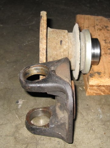
What I'm trying to do is more along the lines of cygnus1 and alteredz, just using factory parts to save some time and money. Just a single piece with two parallel flanges, no splines. One flange with four holes to bolt to the 280Z axle side companion flange and the other flange will have six holes to bolt to the CV shaft flange. I won't even take the 280Z companion flange off of the car, just pop the diff side stub shafts out, insert the CV shafts, insert the adapter and bolt it all together. That's the concept. If you look at the picture in Post #3 you can see the four hole flange on the left (cut down from the u-joint yoke) and the six hole CV flange on the right (with the splined section cut off). Those two parts will be welded together. Thanks for the feedback and the other links. This is just one more way to get some flexibility in parts selection for the future.
-
I guess I'll take some more precise measurements, grab my parts and visit some local shops just to see how feasible it is. The machining of the u-joint yoke might cost more than just starting from flat plate. The CV companion flange looks like it might be a good starting point though.
-
No, sorry, I missed that one. I had already been thinking about it when I started searching so didn't look through all of the results. Thanks for the link. It looks similar to the alteredz website drawing, but with studs instead of through holes. That's similar to what I want, just without the machining costs. A guess on cost to have cygnus1's design made??? Maybe I'm wasting my time. It seems a like a fairly simple adapter to make if you have the equipment, that a lot of people might use if it was available for purchase. The alteredz site referred to the bolt length problem also and recommends cutting them down a small amount. As long as the threads get full purchase on the nut, ~3/4 bolt lengths should work [Edit - actually ~1 inch, I left the length of the nut out - would be very tight], I assume (2 x 1/4" flange thickness, + 1/4" bolt head thickness), but it would be tight. The other option is to put the bolts in from the outside and nuts inside, but that's probably 20 individual aggravations to get them installed. Thanks again for the link. I think that a good lathe and a welder might get the job done, but can't say for sure.
-
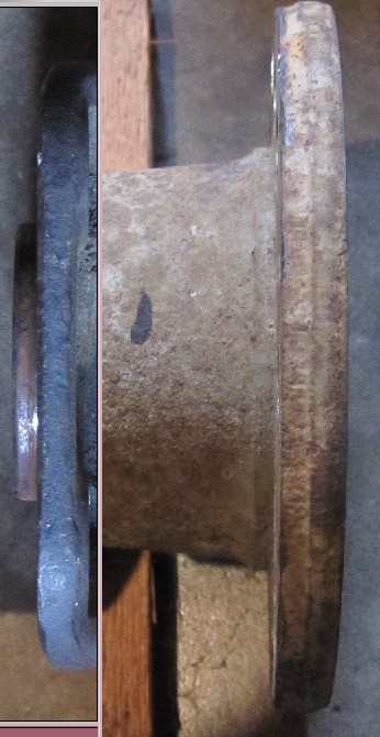
I should have put more work in to my pictures. Here's an edited picture, showing what I was thinking they might look like after cutting/machining (set side by side). The CV companion flange should be easily cut on a lathe (I think), the four bolt 280Z axle side might take more work, to cut the u-joint straps off and grind it to thickness. Welding the two together gives an adapter that connects the four bolt axle flange to the six bolt CV shaft. I'm guessing that they are both forged steel, so if the bolt holes are accessible after welding, maybe with a couple of small gussets or filler for strength, it might work. I'm looking it as I have two parts with 80% of the machining done, with the locating ring on the four bolt side in place and the recess for the CV side built in. Can I finish it and make it work is the question and will it hold up. The car is just a stock 1976 280Z.
-
I have some spare parts to work with and wondered about making an "inexpensive" (maybe) adapter for using 1983 280ZXT CV shafts on a 1976 280Z. Rather than cutting steel and precision machining 20 or more holes to make an adapter, could I cut and weld existing pieces to get the same result. I have the companion flanges from the 83 ZXT and the u-joint yokes from the 76. Could I cut and weld these two pieces together to achieve the same result as described here - http://alteredz.com/280ZCVHalfshaftConversion.htm I've attached a picture with the two pieces aligned to show the two mating surfaces at the approximate distance apart they would be after cutting and welding. I've taken some rough measurements of CV and U-joint shafts and the flanges and it looks like this would work if the adapter is under 1 3/8" thick. The picture is taken with the critical surfaces ~1 3/*" apart. I have little experience welding and don't know what materials these two pieces are made from. I'm looking for insights anyone can offer on the feasibility of cutting and welding these two pieces, plus the effort required to align the four hole side with the six hole side, on center. Thanks.
-
location of headlight relay on 71 240z?
NewZed replied to Sugee_S30_Z's topic in Ignition and Electrical
The 1972 FSM will probably get you close - http://www.xenons30.com/reference.html I believe that there is no relay, headlight power runs through the combination switch and the dimmer switch which is part of the turn signal stalk. Most headlight problems are from dirty contacts in the dimmer switch. -
Maybe the Z31 guys are just low on oxygen - http://www.somender-singh.com/ Groovy, baby!!!!
-
Here's one source - http://www.datsunstore.com/advanced_search_result.php?keywords=fusible&osCsid=b0c32fe5fecd13a94597e8149bc5a3fe&x=0&y=0 Assuming you found the short?...
-
Either should work. Are you sure the coil is good? If you had a shorted coil, you might get a hot module and no spark. Check resistance across coil + to coil -. Most coils are in the 1 - 3 ohm range. Another way to test your coil is by connecting coil + to 12 volts (switched with the key On or a direct from battery), placing the coil output (big main wire) ~.040" from ground, then tapping coil - to ground. Each tap should give a spark. I have tried that, and it does work. If you do it while the coil is mounted in the car, you'll be testing your ground back to battery also. Also, make sure that there's not a problem between the coil and the spark plugs. You might have everything up to the coil output, but a problem between the coil and plugs. It would be nice to confirm that your FIDLE signal is switching from zero to five like it should also. You might be able to see it with a voltmeter and turning the distributor but I assume it's a fast switch. Maybe the MS datalog shows what it's doing while you're cranking? If you can isolate each component and confirm it's operation, the answer will show up. It's just a good general way to problem-solve.
-
What happens if you disconnect G and W and leave B at 12 V and C at coil -? That would be the typical state for the module in its intended use. From this point, you should be able to connect G to ground and then touch W with power to get a spark. Each touch should take the G-W circuit from zero to positive which should give a spark from the coil. I haven't tried this but in theory that's how the module works,and that's what you're trying to do with MS. Isolate the module from MS, see if it works, if it does, then you can focus on getting the right trigger to it from MS.
-
I don't know a bunch about Megasquirt but I have read a little on the HEI 4 pin module. It is designed to control current flow to the coil, then kill the circuit when the G and W wires see voltage go from negative to positive from the reluctor in the distributor, causing the coil to fire . I don't think that G and W are designed to see a constant voltage/current flow, just the transitory "spike" from the reluctor in the distributor, every time the rotor passes the pickup. That's might be why it's getting hot. You might try a bigger resistor before pin G. The module is designed to trigger on very small voltages, less then one I believe, and up to very high. But I don't know that it will work with a square wave setup like you're trying. I think that the Bosch 0 227 100 124 might be a better choice for what you're doing. Described here - http://www.megamanual.com/ms2/Bosch_124.htm
-
How to determine if your camshaft and chain is installed correctly is described in the Engine Mechanical section of the FSM, with illustrations. All you have to do is turn the engine in its normal rotation direction and stop it at TDC, then eyeball the marks. It takes minutes. While you have the engine at TDC you can also check the rotor in the distributor to see if things are correct there. It should be pointing at a spot between straight ahead and the left headlight. Put you #1 spark plug wire where it is pointing, then install the rest in order. These two things are critical to getting the engine to run, but are very easy to confirm.
-
You don't say if it used to work or if this is a new installation. If it won't go in to reverse it's most likely a clutch problem, it's not disengaging. When you do get it in to gear (start it with the clutch pedal down, in gear), does the clutch engage when the pedal is way down by the floor? That's a sign of hydraulic problems. Master cylinder, slave or more bleeding. I have had a slave cylinder go bad within a few months, part quality is iffy from the big parts stores. Check inside the boot on the slave for fluid.
-
The FSMs are out there, on the xenon site.