Chickenman
-
Posts
1051 -
Joined
-
Last visited
-
Days Won
9
Content Type
Profiles
Forums
Blogs
Events
Gallery
Downloads
Store
Everything posted by Chickenman
-
280Z Kick panel speaker pods in development. with content!
Chickenman replied to Derek's topic in Interior
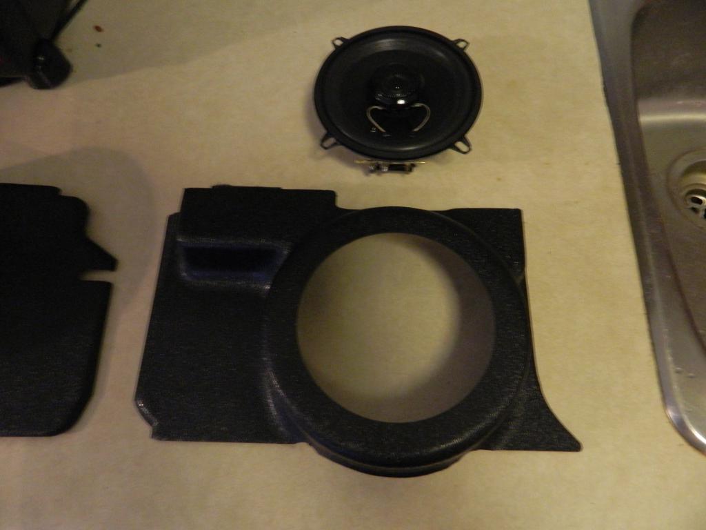
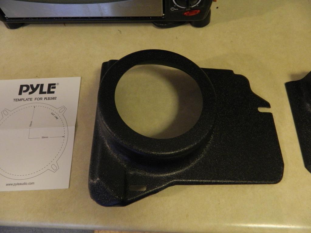
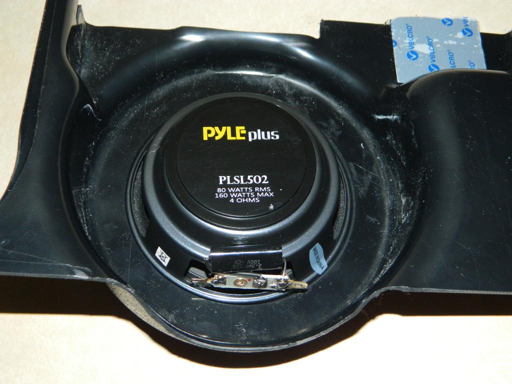
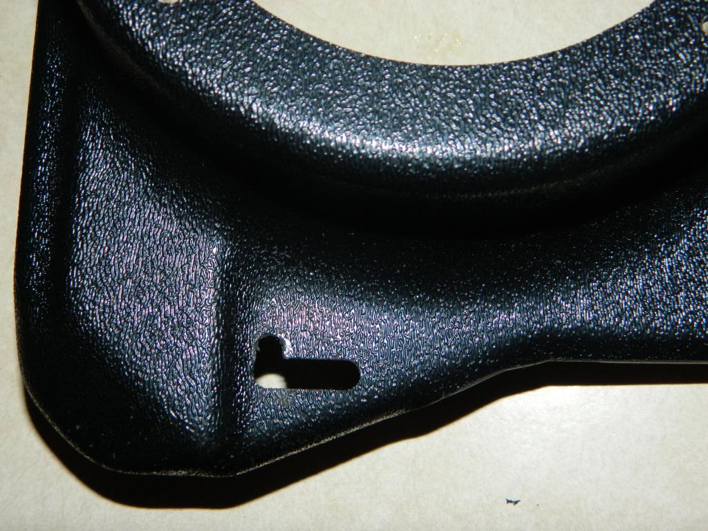
Had to wait for speakers to come in. So here are the first few pictures of the Datsun-Works 280Z front speaker Panels on my 1976 280Z. Fit and finish is excellent. They look factory made. I only had to make one small modification on the drivers side to the lower mounting hole. This may be due to the hood cable being positioned slightly lower on the 1975 and 1976 models than the 77's and 78's. There is a difference in layout between the years. The Pyle PLSL502 fit perfect and are highly rated from what I've read. I got mine on E-Bay for $36 pair USD. The speaker is exact;y 1.643" from the bottom of speaker cone, to the bottom mounting lip of the speaker. On the passenger side panel. there is 1.858" clearance to the top of the fuse box lid.These dimensions may be important to others who may prefer different speakers. There are shallow component speakers available, so now you have the dimensions you need to use alternative speakers.. Didn't get a chance to measure clearance on Drivers side as my back muscles spasmed on me. That put paid to any further work today!!! Suffice to say, that the Pyle PLSL502 speakers will fit. Edit: On the drivers side there is 1.965" clearance to the top of the ECU. Slight modification on drivers side mounting to fit 1976 model.
-
280Z Kick panel speaker pods in development. with content!
Chickenman replied to Derek's topic in Interior
Just picked up Derek's 280Z speaker panels. I must say I am very impressed with the quality of the product. The finish is excellent and looks factory made. Shipping was very fast and well packaged. Will do the initial install tomorrow on my 1976 280z and report back on fitting. I am waiting on my speakers to arrive ( Pyle PLSL502 Shallow speakers ) , and they should be here next Wednesday. Meanwhile the installation and picture I take tomorrow should show up any issues with installs on 1975 and 1976 models. I can also take measurements to see exactly how much space is available. BTW, my car has factory A/C, not that I think that will make a difference to the install.. To be continued... -
Lean running in top end gear pulls, but OK in 2nd and 3rd is usually an indication of inadequate fuel supply. Are you running a fuel pressure gauge that you can Monitor in real time? Dyno pulls show this up more often than the street, because you usually can't do sustained high RPM pulls in 4th and 5th gears on the street for obvious safety reason. A load Cell chassis Dyno where you can load the car up at a steady RPM is by far the best method of testing ( DynaPak is one such model ) If you are losing fuel pressure in Top Gear at high rpm , some of the things to look at are: 1: Correct float level of course. That is a given. Surprising how often this is out of spec though. 2: Adequate fuel pump to supply volume and pressure needed at sustained WOT in 4th gear. Stock Nissan mechanical pump is NOT adequate to feed Triple DCOE's at sustained WOT. 3: Adequate fuel line size. Minimum AN 6 ( 3/8" ) from fuel tank to carburetors. AN 8 ( 1/2" ) is preferred. Return line to tank needs to be AN 6 as well. 4: Non restrictive fuel filters. Again, minimum AN 6 and never EVER use those aftermarket " Glass or Plastic " inline filters. These are horribly restrictive. Stock fuel filters are too restrictive as well. Bad Fuel filters: A proper fuel filter is the Fram HPG-1 or similar. Good Fuel filter 5: What fuel pressure regulator are you running. From experiences with the experienced Turbo tuners on various racing forums ( Including the 510realm ) , there is one name to remember. Aeromotive. Accurate, reliable and non restrictive. Even well known brands such as Holley and Mallory have proven to have many more issues than Aeromotive products. They cost more, but they are worth it. Don't rely on a Chinese clone either. Always run a return to tank Bypass system, even on carburated cars. 6: Correct float Needle and Seat size. Sometimes you need to increase the orifice size of the N&S. This is a last ditch effort though and usually only required on very high output motors. All of the above areas of the fuel system must be checked and accessed accordingly. A weakness in any area can lead to a high rpm, Top gear lean out situation. Hope this helps.
-
Good diagnosing. Finding something like that is really tricky.
-
280Z Kick panel speaker pods in development. with content!
Chickenman replied to Derek's topic in Interior
Have a set for my 76 280Z on order. Plus a set of Pyle PLS502 speakers. These panels are just what I needed to upgrade the sound in my Z. Currently have Pioneer 6X9's in MSA rear speaker panel with a Pioneer deck, but Treble gets lost in the rear deck area.. These should punch it up, along with a 400w Pioneer GM- A3602 Amp and Polk Audio DB1001 Tweeters. I know it's not " Audiophile quality"... but it will do for me. Full details and report on install when I get the parts. -
Where to source counter shaft bearing for the 83 280ZX FS5W71B
Chickenman replied to wigenOut-S30's topic in Drivetrain
If you go to a bearing supply shop you " may " be able to order a high load bearing. These are made with higher quality materials and tighter tolerances than standard Automotive grade. Depends on the supplier and bearing part number if they have a High Load bearing available. -
You're in Canada. That makes a big difference in fuel quality compared to most US blends... and for once it's in our favor. Can you get 94 Octane Chevron or Petro Canada Ultra 94+? Either fuel will support an F54 with flat tops and N42 head with no problems. I run a 1976 280Z with an F54 with Flat tops and N47 head. CR is calculated at 10.3 to 1. I run 12 to 14 degrees Static advance and 34 degrees total mechanical. Ported Vacuum advance adds another 15 degrees at cruise. I've pulled 28 MPG out of this car. ( 3.9 gears with 1983 ZX NA 5 Speed ) I run a 280 degree cam with .480 lift. Car has tons of Torque and pulls HARD to 7,000 RPM. I can run it quite happily on Chevron 91 Octane fuel, but I do get a slight pinging between 4,500 RPM and 5,500 RPM. The only reason it pings ( slightly ) at that RPM range is because of the Factory ECU and stock injectors is causing it to run lean at that range. I have a solution on hand, but am waiting to schedule some Dyno time. Tons of guys out West running Nissan L series engines on Chevron 94 with CR in the 10.5 to 1 range every day in their Daily Drivers. They do have to back timing off by about 2 degrees when they go South of the border though. Same on the East Coast. BTW, I also have an Audi Quattro with a 1.8 Turbo engine. These have a 9.5 to 1 CR and are then boosted. I can run Chevron 91 Octane fuel at 15 to 18 lbs boost and only see about 3 degrees timing pull from the Knock Sensor logging. With 94 Chevron I see Zero...Nada...Zippo timing pull at 18 lbs boost. Canada has some pretty darned good pump fuel.
-
Engine Bay Brace and the Front Won't Turn In
Chickenman replied to 260DET's topic in Brakes, Wheels, Suspension and Chassis
^ Rubber bushing thickness plays a big part in how the above setup works. You don't want a thick, squishy, and soft rubber bushing. Generally something from around 1/4" to 3/8" thick works well for rubber bushes. -
Engine Bay Brace and the Front Won't Turn In
Chickenman replied to 260DET's topic in Brakes, Wheels, Suspension and Chassis
A very simple change that you can make is to replace the front sway bar mount bushings with rubber, if you are using Poly. This gives a progressive roll rate, letting the front end take a set and then stiffening up. I use to do this all the time on my car when I ran Autocross or Hillclimb. Worked very well on cold slicks or DOT compounds. Usually for high speed Road Race tracks, I would put the Poly frame bushings back, but on some tight tracks with slow corners, the rubber bushing just gave the car that initial " Bite " on corner turn-in. It is a very fine tuning method, so you do have to make sure that you have your spring rates and sway bar sizes well sorted. Autocross and Hillclimbs are a bit of a specialized form of racing as you are always dealing with cold fronts on a RWD car. -
Put a stock Camshaft in it. Easier than Intake and Exhaust restrictors and nothing to be found. Take some ignition timing out of it ( 28 -30 degrees total Mechanical ). Set rev limiter to 6,000 RPM or less. Camshaft change will drop your exhasut DB levels as well . An Airbox will take care of Intake DB levels.
-
Numerous Nissan forums seem to indicate that there definitely IS a problem with decoding and sync of the Hi-Res ( 360 slits ) of the Nissan CAS wheels and MS2 and even MS3. This is just one of many links that show the Sync issue with the Nissan Hi-Res wheel. This is from 2014, so it is fairly relevant. Note that this particular thread jumps back and forth between MS2 and MS3 ( which is not ideal , but it is just one example of many ) http://www.msextra.com/forums/viewtopic.php?f=131&t=50336 Here is an excerpt from a thread about problems with an MS3 and the Nissan Hi-Res CAS wheel on SRD20 motors; There are lots more like this on various Nissan Tuner Forums as mentioned. Matt had posted back in this thread as well, noting that the MS3 only used the Hi-Res ( 360 slit ) ring for cranking RPM. At 3,000 RPM it would be using the Lo-Res ( 6 slit ) ring and this he did not know if this was causing an issue: Well, it appears it may well be a factor ( using the Lo-Res ring ). Then there is this comment by " jsmcortina " ( MS Firmware Developer ) that says that the MS2 can NOT decode the Nissan Hi-Res wheel. So you can see how this is all very confusing; Don't quite know how the developers can say that the Nissan CAS modes work correctly, when so many people are reporting problems with the Hi-Res Nissan and DIY brought out a modified ring. If there were no issues, then why the modified ring? Apparently the 6 ring inner ring does not have enough resolution at higher RPM's and is casuing problems in some situations. That seems to be the general consensus on various Nissan Tuner forums. . All in all, the DIY modified ring just seems to eliminate all the confusion and issues. Or an AEM 24 + 1 ring, which AEM also developed to replace the Nissan Hi-Res wheel to solve their ECU's particular issues with the Nissan Hi-Res wheels. . Very confusing situation... Edit: Just found my MS Forum password, so I'll probably be posting more over there... Got no time to work on my 280Z cause I'm spending so much time researching MS2 and Nissan Trigger wheel articles.. Edit 2. Actually I think I'll try and take a break from this thread. Interesting Technical discussion, and it would be nice to get some definative answers. But I've got to get some other work done....
-
Ok, I'm a bit confused by the above statement. If the Factory trigger disc is supported by MS2, then why did DIY bring out the new designed trigger disc and mention on their sites that the MS2 combined with the factory Nissan disc has synch issues? If there are no issues then this is a bit misleading to customers. Something missing here... Is it only when the MS2 uses the outer ring ( 360 slits ) for the Crank signal that this occurs. As you mentioned using the inner ring with only 6 slits has limitations with resolution. Doesn't seem right to me??? Edit: Let me know if I have the following correct. This is what I have managed to glean form MS and DIY sites and is my understanding of the situation. Note this all refers to the 1985 VG31 Nissan ring which has 360 outer slits and 6 inner slits. One slit is larger than the others and is used as a " Home " signal. 1: MS2 will support the factory Nissan 360 slit trigger wheel, but with limitations. It will only work as a " Basic Distributor" so no waste-spark, EDIS . ( Direct fire not supported by MS2 is understood ). Is that correct? 2: Can the MS2 properly use the outer 360 slit ring as it was intended for the Crank signal. MS and DIY seem to indicate that it has synch problems when the 360 slits are used. The fact that you mentioned that you have to use the " Basic Trigger " setup with the inner 6 lit ring on the Stock Nissan wheel ( As The Crank signal ) seems to support this. Is this correct? 3: Which Trigger wheel has superior performance and capabilities with an MS2. The factory Nissan ring or the DIY 24 + 1 ring? If the new DIY ring has no advantages, then why was it brought out? Please clarify. 4: What are the capabilities with the MS3? Can it read the outer 360 slit properly with no synch errors and can it decode the stock Nissan VG31 ring properly to run full sequential Fuel and Direct Fire ignition? Please clarify.. I'd like some clear answers on these questions as I have a friend who wants to modify her 78 280Z and I'm leaning towards the MS3. But I'm not going to recommend it if it can't do full sequential fuel and Direct fire coils ( That's what she wants ). Thanks so much for the advice.
-
One of the interesting things taht came about because of this discussion is that I found I can use Tuner Studio to generate some Fuel Maps to use on my Haltech. My Haltech E11uses older Halwin Software ( version 1.71 ), and will not do VE Calculated Fuel maps. But Tuner Studio will. I realized that I could set up a VE fuel Map in MS Tuner Studio for my 280z, save it as an Excel file, then Import that Excel file ( with a few manual adjustments for scaling ) to my Halwin Fuel maps. That just saved me a couple of hours on the Dyno!! I also tried generating Fuel VE Tables using the latest version of HalTech's ECU Manager, but for some reason the injector Pulse Widths are only about 1/10th of what they should be. I suspect it is just a bug in the software, ( HalTech seems to be infamous for buggy software ) but the Tuner Studio injector pulse widths seem correct.
-
Noted that the DIY wheel has the Trigger and Home rings swapped. Will have to make sure that the wiring on the Nissan CAS is hooked up accordingly.
-
Thanks Matt. I'm giving Derek ( MS2 owner ) a hand setting this up. I was thinking that you could swap the Trigger outputs from the Dizzy and use the 6 slits to make it run, but I was worried about the resolution with so few slots. Your wheel is an elegant and inexpensive solution to the problem of the 360 slits. Derek had tried running Fixed Advance disabled and " Using Table ". Didn't work. We'll check out the wiring and spark settings when he can get access to his car again. ( Presently it's 350 miles away ). I'm making a Base Line Tune for him on Tuner Studio and send him the saved .msq file so he has a safe starting point. ( I go with with very conservative Ignition Maps until you get the Fuel Map dialed in ). As soon as he's back he's going install the new trigger wheel and physically check the Box to see what is going on and how it's wired & jumpered etc. We'll then hookup via Remote Access and I can help him diagnose and setup his system from there. I recall now, that when I was looking into MS for my 280z, I was trying to decide on the MS2 or MS3. Was swinging towards the MS3 as the MS2 couldn't do full sequential on the 6 cylinders. I'd forgotten about that. So it's Multi-Point or Batch fire only. Any limitation on Batch Fire with the MS2 and 6 cylinder motors? Thanks for the clarifications. One of the poor qualities for Haltech is their lack of support for older products. MS is just awesome in that respect. I ended up buying a good used HalTech E11very cheap with fully configured harness and LS2 coils ( Came off another Inline six ) . In hind site I should have bought the MS3... but the budget came into play and I simply couldn't pass on the Haltech E11-V1 bargain. It will do everything I want, but zero support ( and I mean ZERO ) on the V1 variant. We'll probably be seeing you over at the MS forums. Thanks again.
-
Buy a cheap used Laptop that is loaded with WinXP ( or Win7 ). Price = Free to $100. You don't need a fancy Laptop. Just about anything within the last 10 years will run Tuning Programs just fine. Any decent system requires a Laptop to tune IMHO. You can do so much more with a Laptop than a corded Programmer. Much better for Data Logging as well.
-
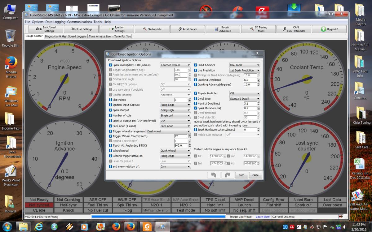
OP: ( What's your real name? ) Here is a screen shot of Tuner Pro, setup for the DIY Nissan Trigger Wheel. MS2 3.30 with Extra. Should be same setup that you have. This is setup as a Dual wheel. This gives you the most Fuel and Ignition Options. IE: You can run MultiPoint ( non-timed ) Injection, Batch Fire or full Sequential injection. Notice how the Options that were previously Greyed out under " Basic Trigger " are now active and selectable. Note: Ignition side is setup for a single coil in screenshot, but you could also run WasteSpark, EDIS or Direct Fire Coils ( COP ).
-
Yes, first Haltech, but I've been Burning Chips and Tuning on Bosch Motronic ( ME5.3 and ME7.X ) , and tuning SDS, and a few MS1 and MS2 systems since 2006. HalTech already works 100% in simulation with all sensors connected and gets correct signals from Dizzy and fires ignition and Injectors ( Checked with NOID lights ). It should start and run on first turn of Ignition key, ( Unless I do something stoopid... which is possible ) and I already have a good set of Ignition Timing Maps to use. Fuel Maps need the Dyno.
-
And what I'm saying is the DIYAUTOTUNING NOW has a better solution than Moby's and is much easier and cheaper to apply. The DIY Trigger wheel only costs $28. Moby's article on that you referenced on the Z31 Dizzy was written in 2003. The MS2 that the OP has wasn't even made back then. Edit : Just re-reading the Moby article from 2003, and it's for the MSnS ECU... which is a fuel only ECU. None of this article is at all relevant to the OP's MS2 ECU, which is completely different hardware from MSnS. The new Trigger wheel information by DIYAUTOTUNING was last updated Dec, 18,2014. Which article do you think is more up to date? And if you read the article on how to setup the DIY Optical wheel you will see that they mention the Improved resolution of their new trigger wheel. Edit: And once more for information. DIY's latest recommendation ( As of Dec, 18th, 2014 ) for running the revised Trigger wheel for Nissan Optical Dizzy.... on MS1, MS2, and MS3. https://www.diyautotune.com/support/tech/hardware/nissan-trigger-disc/
-
You really are in over your head aren't you.... and just won't admit it. You like to cut and paste articles but you really don't understand the " Details " of the problem. Do you even bother to read the Links that I post? I posted a Link to the Full article from MegaSquirt that explains why they brought out this special Nissan Trigger Wheel. Sounds like you skipped over reading my links .... again. MS designed that particular wheel to address problems with that owners of MS2 had with running the 360 slot CAS wheel in the Nissan distributor Optical . The main problem being that the processor did not have the processing speed and power to properly read the 360 slit wheel that Nissan uses. You would have signal sync loss at high RPM's. That is a KNOWN issue for people who have experience in these matters and was never able to be solved satisfactorily. I researched MS2 boxes for many months and had decided on an MS2 or MS3. Then I happened to come across a great deal on the Haltech which I couldn't pass up. The links that you keep referring to by Moby are back in 2003 and 2005. Over 10 years ago, and before the Custom rings were made!! Moby's idea was an attempt to write new code to the MS2 firmware so that the Nissan 360 slit Optical rings could be decoded. This never worked well as at high RPM's the ECU was limited by the processor and Read resolution was dropped. That was the " Band -Aid " fix I was referring to ( and other failed attempts to resolve the Sync issue with Nissan Optical CAS ) and that is why DIYAUTOTINING made their special Trigger Ring for Nissan Optical distributors. The new Trigger ring solved ALL of the issues on the MS2 that they had with the Nissan Optical wheels and it only costs $28. It was an elegant solution that didn't require owners having to change out the CPU on the MS2 box to solve the Sync issues... which would be ridiculous. BTW, AEM also has a special Trigger wheel designed for the Nissan Optical for some of their older ECU's that uses a 24 - 1 wheel. They had precisely the same problem as the MS2 in that they would lose signal sync at high RPM's. The processor just wasn't fast enough to keep up the read and calculations needed . Their firmware could decode the ring... but that's only half the probelm. AEM has them in 50mm and 54 mm sizeszes to fit various Nissan Optical distributors. I'm using the AEM 30-8762 wheel on my Haltech E11 system. Although the Haltech E11 has a much faster processor than the MS2, has the proper decoding algorithms and has a processor fast enough to read the 360 slit rings with no Sync loss, HalTech Australia ( Main world head quarters ) recommends running a Crank signal with 12 to 60 rings maximum. Why? Because a Nissan ring with 360 forces the processor to run at Near full speed and that generates a LOT of heat which shortens CPU life. 24 - 1 ring will provide all the resolution you need, lead to less Sync loss and allow the CPU to run slower which = less heat = longer life. Finally on to your misunderstanding of what a Basic Distributor is in regards to an MS2. A Basic Distributor in the Tuner Studio software refers to an Old style mechanical and vacuum advance controlled distributor. The distributor handles all of the ignition advance curve. Once you select " Basic Distributor " Spark Mode in the setup, ALL of the advanced programmable settings will Greyed ( Locked ) out. You cannot use the advanced ECU controlled Ignition Maps... PERIOD. And that is what the OP wants to do. The Nissan Optical Distributor is NOT a " Basic Distributor". It has no mechanical/ vacuum advance mechanisms built in. In reality it is a separate Crank sensor and Cam sensor built into a Distributor housing. And it has to be setup as such. Basic Distributor is the wrong setting for Spark Mode in Tuner Studio. NZ or ZH , I know you have good intentions and have been a great assistance to the community over many years. But you have a tendency to try and be the Head Guru on various forums. To that extent you seem to go out of your way to argue points by cutting and pasting articles to support your side of the argument... just for arguments sake and even without fully understanding all of the Technical issues. Maybe you should consider that there just may be other people out in this world who may have a better understanding of a certain subject than you. And maybe it would be wise to sit back and listen and perhaps learn something from what they are saying, instead of constantly trying to discredit them. I'm not going to get into a pissing match with you over this. It's just a waste of bandwidth and doesn't help the OP one Iota. I do know what I'm talking about. I've had a lot of experience in the areas that I discuss, both in Automotive and Electronics. . I don't drag you down in your fields of expertise... so please give me some respect and don't try and drag me down in my areas of expertise. Richard Boyk
-
^ What are referring to ZH with your attachment? What are you trying to say? In my Post #24 I included a link to a MS article that fully covers the Nissan Optical Trigger wheel issues when running the MS2 . They developed that wheel to address specific issues without having to resort to " Band-Aid " fixes. I also Copied and Pasted the settings necessary for the MS2 and that particular Trigger wheel, just to make it easier for OP.
-
Just to cover EMI: 1: Always use resistor plugs. 2: Always use Top Quality spiral core wire ( MSD, Magnacore, NGK are all good. Taylor & Nology are not recommended ) . Never EVER use Solid core ( or even ) Carbon core wires with any stand alone ECU. It's good quality spiral core wires or nothing... unless you like hunting down mysterious Trigger errors and such. 3: Always keep the Ignition trigger wires routed well away from any HT leads but also the 12 volt power leads. The Ignition Trigger wires are very susceptible to EMI and should always be shielded wire or " Twisted Pair " wire. 4: If you are using an MSD or Crane style Ignition box, it must be mounted at least 3 Feet from the ECU. Aftermarket CDI or high power Inductive boxes produce massive EMI and must be well separated from the engine management ECU . Have a look at the factory ECU system on 280Z's. There is a reason why the Engine ECU is on the driver kick panel and the Trignition box is on the passenger kick panel. EMI isolation.
-
The jumping is likely because the MS2 processor cannot properly decode the Nissan trigger wheel. The Nissan trigger wheel has 360 slits on the Crank Trigger Ring. 360 timing slits is a LOT of reference points. That takes a very fast processor to handle the calculations at higher RPM's. The MS1/MS2 hardware and it's firmware are not designed to work with the Standard Nissan wheel. ( The MS 3 can handle the stock Nissan V31 trigger wheel, as it does have a faster processor and the necessary firmware to decode and calculate the Nissan Trigger wheel properly ). It's all documented in the MS Tech forums when you dig deep enough. The MS2 can likely " stumble " by on basic settings ( at lower RPM's ) acting as Basic Distributor setup. But it can not work properly in full ignition Table mode. It's just not possible. That is why the OP has to change Trigger wheels to one compatible with his MS2. Edit: There are other things that can make the Timing jump as well, most dealing with EMI. But that is not the main issue right now. First the OP has to get the proper Trigger wheel that is compatible with his ECU and setup the proper parameters in the Software.
-
Yes and it's all done by the software. Don't try and over think things. Get the correct Trigger wheel and follow the instructions provided from MegaSquirt for that wheel. You ALWAYS need to set the trigger offset. That is a fundamental method of how Electronic ignition timing tables work. You don't really have to know how " Predictive Algorithms " and all the engineering details work. That is just going to hurt your brain and make you more confused. ( The following book explains things in Layman's terms that the common person can readily understand ). I would really recommend getting a book called: " Performance Fuel Injection Systems " By Matt Cramer & Jerry Hoffman. ISBN 978-1-55788-557-9 Both Matt and Jerry are key members of the MS design team. This is a MUST HAVE book for MS owners. Here is the simple version to understanding how ECU's control ignition timing and what Crank and Cam triggers do. 1: You have to understand that Mechanical Dizzy's ( with weights, cams and springs and vacuum pots ) physically moves the Distributor Plate ( Points, Optical or Magnetic pickup ) in relation to the TDC point. So you can advance the ignition timing by physically moving the sensor point. This adds mechanical or vacuum advance. The Cam lobe or Reluctor wheel tells how many cylinders the engine has. This equates to the Trigger ( Crank signal ) on an ECU controlled system 2: With an ECU controlling the Ignition timing table the Crank signal ( Trigger ) and Cam signal ( Home ) things are totally different The sensors are in a fixed position and do not do not move. So how the heck can we adjust the timing back and forth in Real time electronically? Simple: By using a " Home " signal that tells the ECU that #! cylinder is approaching TDC. This " Home " signal is usually positioned at least 60 - 70 degrees before TDC. Why? Because total ignition timing is an additive of Static timing + Mechanical advance + Load ( vacuum advance ). This figure can easily total 45 to 50 degrees under cruise conditions. IE 15 static + 20 Mechanical + 15 vacuum/load advance = 50 degrees. The ECU needs some time to perform these calculations ( At 7,000 rpm it's all in micoseconds ) so we add a " Buffer " of 10 to 20 degree for it to have time to make it's calculations. Scenario A: So the ECU now gets a signal that #1 piston is now at 70 degrees BTDC. It looks at the Timing table and sees that at this particular RPM ( 800 rpm ) and particular Load we want an ignition timing of 10 BTDC. So it calculates all the numbers in microseconds and sends a signal that fires the coil 60 crankshaft degrees later ( 70 degrees BTDC - 60 degrees = 10 BTDC ) . Scenario B: Now lets see what happens at 7,000 RPM at WOT. ECU now gets a signal that #1 piston is now at 70 degrees BTDC . It looks up the Timing table and sees at 7,000 RPM and a HIGH Engine load ( 0" vacuum ) we want an ignition timing of 35 BTDC. So it calculates and sends a signal that fires the coil 35 crankshaft degrees later. ( 70 degrees BTDC - 35 degrees = 35 BDTC ) So by knowing the engine RPM and number of cylinders from the Crank ( Trigger ) signal and the position of the #1 piston by the Cam ( Home ) signal we can now have full control over BOTH the ignition timing table and fuel timing table. You can run Sequential Fuel injection and Coil on Plug tuning just by knowing the 3 variables. RPM, Number of Cylimders and #1 piston position. In the simplest setup ( Basic or Distributor setup ) , you can have multi point Fuel injection with just a Crank sensor giving RPM and number of cylinders. That will give you Multi point or Batch Fire Fuel control ( but not sequential ) and you could run it with a standard weights and springs style distributor. The light should be going on right now... because that is essentially how you are running your setup right now.... but you do NOT have a regular weights and spring style distributor. You have a LOCKED distributor with no mechanical advance or vacuum advance ( Essentially you have a fixed Crank sensor and Cam sensor ) and that is why your Ignition timing is locked. Once you get the correct Trigger wheel, and apply the correct Trigger settings, your MS2 ECU will be able to apply the proper algorithms for the new 24-1 Trigger wheel and make full use of the Timing Tables.
-
What I have done is ordered an extra distributor cap. You drill a hole on top of the cap at #1 Terminal so you can shine the timing light through and see where the rotor is firing in relation to the terminal. You should then be able to adjust the distributor body and adjust the trigger angle to keep the spark aligned with the tip at minimum advance and maximum advance. I don't think you can change the position of the actual rotor on the Z31 dizzy. Our setup is not the same as what MSD shows in their video's of phasing with a two piece adjustable rotor on Chevy's and Ford's. You'll have to play with things a bit. You may not even have to phase things at all, as Nissan has probably already designed the correct phasing in the Optical Dizzy. The Chevy and Ford dizzy's shown in Rotor phasing articles and video's were not originally designed to be used with an ECU controlling the timing curve. The Nissan Optical dizzy's are. I'd recommend setting the Dizzy up initially with it bolted down in the center of the slotted mount holes on the Dizzy base. Then you can adjust either way...if needed. The spare Dizzy cap with the hole drilled at #1 terminal just makes it easier to check when running.