z240
-
Posts
397 -
Joined
-
Last visited
-
Days Won
4
Content Type
Profiles
Forums
Blogs
Events
Gallery
Downloads
Store
Everything posted by z240
-
G-Machine tension rod pivot Kit... Is this safe?
z240 replied to SDgoods's topic in Brakes, Wheels, Suspension and Chassis
The best way to get that nasty boot is on is to fold it back over itself, inside out, about half way, then push it close to the lip, and up-fold it over the lip. No heat, no swearing, no muss no fuss. -
I sounds like you haven't come to the realization that you will have to cut the original fender arch out to make any decent tire combo that fits under the flairs "work" ...
-
Fan belt is loose or glazed. Relax. At least its easy to tighten and see if it persists
-
Absolutely concur with the Blue Sea products. It will outlast your car. Worth every penny in the long run.
-
Stud/Bolt/Nut size for Water Pump to Fan Clutch
z240 replied to jimskillet's topic in S30 Series - 240z, 260z, 280z
6m x 1.00mm Use fresh lock washers, but any 6x1 nut will work just fine. For balance, use all 4 the same at least -
Awful squeaking noise from the rear suspension, solutions?
z240 replied to osirus9's topic in S30 Series - 240z, 260z, 280z
Spring noise is highly unlikely. Tighten the nuts at the back of the diff where they pass through the moustache bar. Replaced your front diff insulator? How much of that gross super sticky white lube did you use on your new poly bushings? Put it in the right place? -
This one is $158! Same item, same PN, same company. http://www.ebay.com/itm/75-78-NISSAN-DATSUN-280Z-FAIRLADY-Z-S130-JDM-3-ROW-FULL-ALUMINUM-RACING-RADIATOR-/161123414156?pt=Motors_Car_Truck_Parts_Accessories&fits=Model%3A280Z&hash=item2583b4308c&vxp=mtr I wish I had the kutzpah to put the same item on ebay for two wildly different prices to see who would buy the expensive one! Mind you, I would have fun telling them why if they ever discovered the difference and wanted to know the reason they had been "ripped off"... Now mind you item # 230936863079, an 800 ml Aluminum rad overflow bottle, is a bargain of $765 ($135 off the regular price of $900) is a real steal!! Clearly I'm in the wrong business....
-
Electrical Issue - Blowing fuse when connecting battery
z240 replied to Stresspuppy's topic in S30 Series - 240z, 260z, 280z
We can't tell you what the problem is, but here's how to go about finding it You-all got a short to the chassis somewhere on the power side of the circuit. The fact that it blows the the fusible link before any fuse says it not something any fuse powers. So its big stuff. First disconnect the alternator white wire and see if that stops the fuse blow. Then pull the fuse block its mounting and make sure the white red wire there is not touching anything it shouldn't (metal or chassis). Get your multi-meter out. No multi-meter? Get one. 8-10 bucks at harbor freight or auto-parts store. It tells you if point A is electrically connected to point B and what the voltage is at any point in the harness. This is a requirement for finding electrical problems, short of (pun there, sorry.,,,) finding an obvious place where the white wire's insulation is broken/cracked/worn and touching the metal part of the car. That fat white wire with the fusible link that blew, right off the starter that goes into the harness goes a couple of easy places to check. 1. To the ammeter 2. The fuse block under the front of the console. 3. To the ignition switch. Trace that wire back and find out where it rubbed through and shorting to the metal of the car. The multimeter will tell if you have a connection between the metal of the car and that white wire now. You should not, but you likely do. Keep disconnecting things until the white wire is no longer connected to the metal, then look between the last place you disconnect and where you just disconnected. Good luck. -
And is he welding on the gas tank? Of course he is.... Come on, he has two 4x4''s incase one breaks. What can go wrong.
-
Actually the 78's were the first to have an internal regulator. 78 FSM EE-21 If you happen to have replaced it with an earlier model that requires an external v-reg, this may be the cause.
-
Do an EBAY search for "CREE H4" There are a TON of products out there. A wide range of pricing and quality I'm sure.
-
Well, the back edge will fit, but will leave a bit of a gap showing more door frame. The button hole is the only real issue. Throw them on and see how they fit.
-
77-78 door panels are different from earlier 74-76 panels in two key ways. The location of the lock button is 9" from the rear on 77-78 , AND the angle of the back edge is steeper, making them an akward fit to early 280 doors. This accomodates the changes to the door latches that changed on those late doors that use part of the back edge of the door. We've had this discussion several times already. The key to look for is that long 9" door lock button location to know if you're buying early or late panels. 9=late 5=early.
-
If its hollow, it must have a hole/split and is filling with gas. If its new, send it back for a replacement. If not, use a gank tank sealer to seal the hole/crack. POR makes a sealer. Don't use anything that will add much weight.
-
my 240z starts when i turn the key off
z240 replied to Turbo72-240's topic in S30 Series - 240z, 260z, 280z
There are a pair of loose (red? red-black?) wires that hang off the side of the ignition switch that are part of the interlock. ie when you turn to the lock position these wires either get connected or disconnected. Makes the seat belt buzzer go off or something. If you have mistakening used these wires in another way, then this might be why turning your key to lock has an electrical result you aren't expecting. -
HELP On My Own 1973 Body Harness Near Completion
z240 replied to mainboyd's topic in S30 Series - 240z, 260z, 280z
Its the only BY wire on the schematic that makes sense positionally on the harness. Every wire has two ends, see if its other end make sense as to where it connects given the schematic and your harness. -
HELP On My Own 1973 Body Harness Near Completion
z240 replied to mainboyd's topic in S30 Series - 240z, 260z, 280z
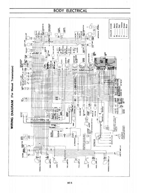
Here is the 73 wiring diagram from the FSM.
-
HELP On My Own 1973 Body Harness Near Completion
z240 replied to mainboyd's topic in S30 Series - 240z, 260z, 280z
Glad to help. The yellow white is the water temp sensor on the thermostat housing. The only black yellow in that vicinity in the engine bay likely goes to something like a solenoid or vac operatied switch on the intake manifold that has escaped my memory. -
HELP On My Own 1973 Body Harness Near Completion
z240 replied to mainboyd's topic in S30 Series - 240z, 260z, 280z
The little round switch in post 7 is the back up light trigger switch that goes in your transmission. The brake light switch is similar, but generally cleaner, has smaller threads, and likely has a lock nut on the threads to lock the position once its aligned to the brake pedal action. The last three wires in the last pair of pictures in post 7 are to the washer bottle (pair) and the long one with a round bullet connector goes to the brake balance/warning switch on the brake line below brake master on the side wall down there by the frame rail. That should just about do it. -
You can't compare the 77 and 78 relay bracket. MUCH was changed in that area for 78 with the fuel pump relay set moving to that bracket PLUS new special FI fusible links hanging on the bracket. Poor Alex is confused enough. The silver thing is the voltage reg. Even that changed in 78, ie no more Vreg, alternators went internally reg'ed.
-
Was WTB: 280Z R200 Rear Transverse Link Mount - OOPS! NEVERMIND
z240 replied to Q*bert's topic in Parts Wanted
It changed when they moved the diff back to straighten the half shafts to remove vibration. Beginning of 72 production according to zhome.com -
Not so much useless, think of it as only a go/no-go device. If its on the right, be happy and keep driving. If its on the left, go straight home.
-
Only thing the ammeter indicates is this. If it swings right of center, current is going through ammeter one way. if it swings left, current is going through the other way. How much it deflects measures how much current is going through. That's it. Now, if the ammeter is in the circuit where its supposed to be, ie between the alternator output and the +terminal of the battery, and hooked up the right way, then swing right means current is flowing into the battery. The opposite is also true, swing left, then current is flowing OUT of the battery. For the current to flow into the battery, the voltage (the thing that pushes the electrical current) must be higher at the alternator output than at the battery + terminal (measured to ground). The whole uphill/downhill thing. Voltage is height, current is the amount of water flowing down the hill. Simpliest thing ever to measure if your alternator is working. Turn car off. Measure voltage across battery terminals. Note voltage. Start car. Do voltage test again. If voltage is higher, then alternator is "working" and battery is taking current. Ammeter should be on right (+) side of center indicating "Charging". Opposite is also true. Can also check voltage at alternator output terminal (other lead to ground) compared to battery + term in both run/no run. Should be same as at battery, if not there is a problem with the connections between here and there. Exact voltage measurements run vs. no run determine state of battery and charging system. Common problems include voltage drops across bad connections, all along the wires involved, from battery cables, fusible links, ground connections to the frame and alternator connections. Like anything else, without clean connections at all points, finding problems becomes very difficult and misleading.
-
Was WTB: 280Z R200 Rear Transverse Link Mount - OOPS! NEVERMIND
z240 replied to Q*bert's topic in Parts Wanted
Have a look underneath, you should already have the curved link. -
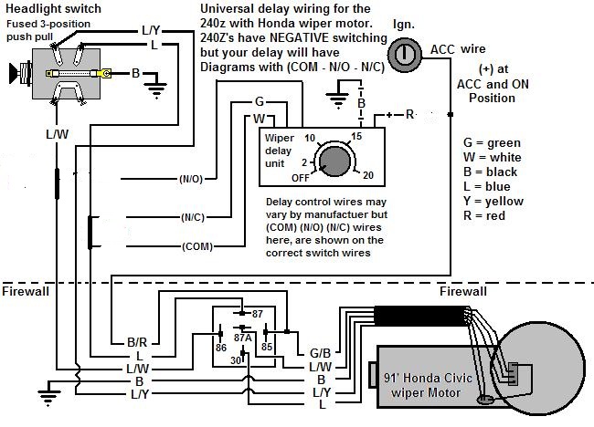
If you simply want to use that diagram, but do not want to use the delay box, then the wires labeled N/C and COM (G and W) need to be connected and the wire labeled N/O should be left disconnected . Like this. Just pretend the delay unit was never added to the diagram. All the scissor and "just tap" stuff was added to it to include the delay box, so put it back the way it was before. Hope that helps. Jim