

Xander
-
Posts
319 -
Joined
-
Last visited
-
Days Won
2
Content Type
Profiles
Forums
Blogs
Events
Gallery
Downloads
Store
Everything posted by Xander
-
The engine I was running was indeed fuel injected. But I have recently swapped in a 305 SBC also running om megasquirt. I am still considering LPG though.
-
Technically it is the other way around. With the engine running the alternator is feeding the battery via a fussible link. A drained battery can also pull a great amount off amps. That is why it is recommended that a completely drained battery is charged off the car.
-

How to create a "Minimalistic" Engine Bay Look?
Xander replied to Sleek Z's topic in Body Kits & Paint
I have seen this pictures around a lot of times but this is the first time I noticed the Air temperature sensor on the driver side shock tower. Is he running megasquirt??? -
Alternator wiring missing NEED HELP ASAP
Xander replied to Mikey's topic in Trouble Shooting / General Engine
maybe this will help. http://www.zcarcreations.com/howto/voltreg.htm -
LOL. one cool looking hamster though. I raced one of these wasps to about 130 mph on the freeway here in Holland. We were almost exactly matched in acceleration and speed. I had a decent running l28 turbo with about 15 PSI of boost at the time. He was surprised that I could stick with him. He told me later that He would out run the new BMW M5. We stopped at a traffic light to turn right. when the light turned green he floored it and before he exited the corner he was doing at least 60 mph. He was running track tires on the street and that combined with the low weight made that thing corner like a F1 car. His car was about 10 times more expensive than mine though .
-
Lotus exige S comes to mind
-
I used to own one of these. Suzuki SC100GX great little runner.
-

From the album: dutch datsun 260z
-
The magnets have to be evenly spaced. 120degrees for a 6 cylinder and 90 degrees on a v8. Have you read the magnet guide at SDS? it goes into detail about how to place the magnets. http://www.sdsefi.com/em2def.htm#EM-2E here is the link. there used to be a better page with pictures, but I can't seem to find it right now. Basically what you do is set the engine to TDC and then mark the place on the pulley where the trigger sits. The first magnet is located 60 degrees from there. A great advantage with the 6 cylinder engines is that it doesn't mater in which direction you go. if you accidentally place the trigger 60 degrees in the wrong direction then the next magnet you place will be right where it should be. because they should be placed 120 degrees apart. The exact placement of the magnets in relation to the trigger is Less important that having them exactly 120 degrees apart. The trigger angle can be trimmed in the megatune software. I have used a stock VR distributor too. It worked well, but the hall setup was more accurate. edit: this was the link I was looking for http://www.sdsefi.com/techhall3.htm
-
This may sound stupid but I had the same issue with an old version of the firmware. If I set the trigger angle to -10 it would not use the table. My solution at the time was to type in -20. It would automatically jump to -10 and it would start using the tables. weird but it did work. Also what are you using to trigger the MS unit?
-
From the album: hall trigger
board connections -
-
-
From the album: hall trigger
board connections -
From the album: hall trigger
pin output of the hall switch -
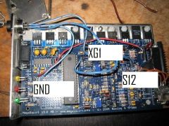
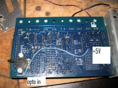
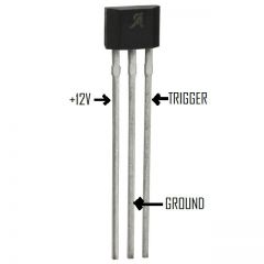
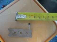
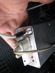
A while ago I was checking the timing on my 305 SBC. A was using the stock (7pin) ignition that came with the engine. It was a TBI engine so the ignition was already computer controlled. There was no advance mechanism in the distributor. When I Checked the timing at idle I fixed the ignition advance to 12 degrees with my megasquirt. The timing was jumping somewhere between 5 and 20 degrees!. When I gave it some gas it became a bit more steady but still no where near what I would consider rock solid. Also when I accelerated the engine to about 3000 rpm the timing would shift a couple of degrees. This combined with a strange trigger mis at 2200 rpm made me deside that the stock trigger is junk. My old setup on my l28et consisted of 3 trigger magnet in the flywheel with a homemade trigger using a small hall effect chip. This setup was very cheap and very accurate. I build the same setup for my SBC. I did not feel inclined to remove the engine to get to the flywheel so the trigger magnets had to go in the balancer. When I took the balancer of I was pleasantly suprised to see that GM already drilled 12 evenly spaced holes in it. 4 allen head bolts where bolted to the balancer and the heads where drilled to a slightly larger diameter than the magnets used. The magnets where bonded in place with epoxy resin. BUILD THE TRIGGER BEFORE YOU GLUE THE MAGNETS. The magnets only work one way. If they are installed the wrong way around they will not trigger the switch. if you build the trigger first you can check the magnet orientation by setting the output of the middle led on the MS unit to trigger IRQ. This will make the led light up when a trigger (magnet) is present. I used a blue marker to mark the trigger side of the magnet before glueing the in. The trigger was a small hall switch which cost about 2 dollars. It is tiny but works very well. I built an extra connector into the megasquirt unit so that I could use a shielded wire. The connector is a mini XLR connector used on guitars and such so it is built to withstand a bit of fibration and it will not easilly come apart. The trigger itself is bonded to a piece of aluminium and bolted to the front of the engine. Conclusion The stock ignition pickup on a tbi SBC v8 is junk. An easy way to install a new trigger is to do the above. It works like a charm. The ignition is very accurate and it does not shift at higher rpm. At idle (500 rpm wit this engine) there is still a little bounce which is probably due to the low resolution of using only 4 magnets. This is where a 36-1 trigger wheel would be better. But at anything over 1000 rpm this small bounce disapears. Did I mention that this is a very cheap setup. Anyone with a soldering iron and an angle grinder can build it. this would be an appropriate switch http://search.digikey.com/scripts/DkSearch/dksus.dll?Detail?name=620-1047-ND it will work within a voltage range of 4.2 to 24V. temp range of -40 to +150 deg celcius. When viewed from the printed side pin 1 (left) is connected to a decent power suply. This can be pretty much anything from 5 volt from the megasquirt mainboard or straight battery voltage. I used a sanctioned 12 volt supply from the megasquirt board. The middle pin is the ground connection. There are plenty places on the mainboard to connect this pin. I used the ground pin just above the proto area on the v3 MS board. Pin number 3 (on the right) wil be directly connected to the output side of the opto isolator. The input side of the opto isolator is connected to a 5 volt suply. With this setup you are not triggering the positive side of the opto isolator but instead the hall trigger grounds the negative side when a magnet passes by. Don't forget to connect OPTO out to TSEL. This connects the opto output to the megasqiurt ECU. This blue lead connects the opto in to a 5 volt source. these bleu leads connect to the hall effect switch. XG1 is the negative side of the opto isolator. S12 is a sanctioned 12 volt supply and GND is the ground. This is basically the same setup used by SDS. Please check there website for more information regarding sensor placement http://www.SDSEFI.com
-
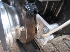
From the album: hall trigger
hall switch bonded to the aluminium plate and bolted to the front of the engine. -
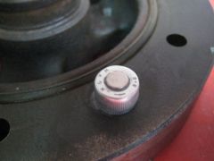
From the album: hall trigger
the magic component -
From the album: hall trigger
extra connector on the megasquirt unit. The wire is shielded. -
From the album: hall trigger
magnets installed -
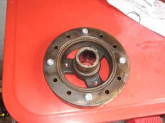
From the album: hall trigger
this is the stock balancer on my 305 sbc -
this is what I did. drain tank and remove the sending unit. ad water and gravel. shake the tanks until your arms fall off and then shake it some more. when all the rust is gone remove the water and rinse thoroughly. rinse the tank with a degreaser. coat the tank with your favourite epoxy resin. make sure that the pickup lines don't get clogged with epoxy. I did not use the original fuel pickup line. I opted to weld some 3/8 npt bungs. good luck.
-
great car. I have been looking for a filler neck like that. Where can I get it?
-
Are you sure about that? I always thought that a three wire sensor had a signal wire (black) and two heater wires (white). It grounds via it's connection to the exhaust. check this site for reverence http://www.tomco.co.uk/PAGES/Technical/oxygen%20senors/refchart/refchart.htm PS: I beleive the 300zx had that weird titanium sensors.
-
I think you could consider this Hybrid music. American rock japanese style!!!. http://www.youtube.com/watch?v=IC_fLUvm16A&eurl=http://www.flabber.nl/archief/022987.php Awesome.
-
It would be cool to build your own but summit sells one that is only $119. There are plans out there for a simple analog multispark CD ignition. http://www.wbnoble.com/WN_articles/CD-ignition-SK.pdf http://store.summitracing.com/partdetail.asp?autofilter=1&part=SUM%2D850602&N=700+4294925143+400304+115&autoview=sku