tube80z
-
Posts
1401 -
Joined
-
Last visited
-
Days Won
31
Content Type
Profiles
Forums
Blogs
Events
Gallery
Downloads
Store
Everything posted by tube80z
-
Bumpsteer adjustable tie rod ends
tube80z replied to JMortensen's topic in Brakes, Wheels, Suspension and Chassis
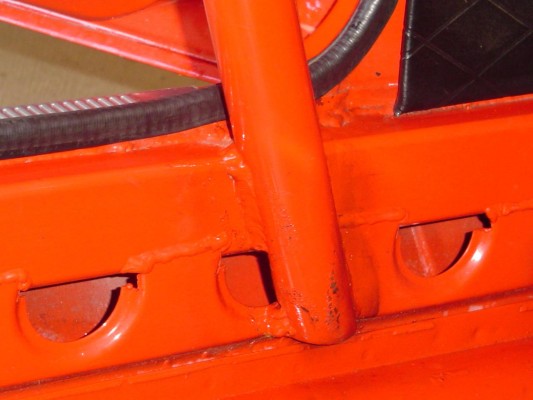
Take a look at the second pic at http://picasaweb.google.com/tube80z/Parts The inner is unscrewed the rack end drilled. If it still doesn't make sense let me know and I'll try powerpoint cad again Cary -
rear poly bushings on outboard end of CA
tube80z replied to blueovalz's topic in Brakes, Wheels, Suspension and Chassis
Why not cut as shown and then mount the adapter in some squaer tube and mount it straight on the control arm. This could easily be welded up and takes care of the angle problem. I'd do something similar on the inside too. Cary -
Bumpsteer adjustable tie rod ends
tube80z replied to JMortensen's topic in Brakes, Wheels, Suspension and Chassis
Remove the inner tie-rod ends, chuck it in a lathe, and drill for a standard size bolt. Then build a clevice out of steel (drill a few holes, band saw, then dress with a grinder) that you bolt to the rack. This clevice will hold the rod end. Below is a pic of one way this can be done (not really a clevice). Cary -
Bumpsteer adjustable tie rod ends
tube80z replied to JMortensen's topic in Brakes, Wheels, Suspension and Chassis
Jon, those look pretty good. Cary -
Bumpsteer adjustable tie rod ends
tube80z replied to JMortensen's topic in Brakes, Wheels, Suspension and Chassis
The tie-rod part won't fit in the tube? A couple of options. You can slit the tube with your grinder lengthwise and see if that will let you slide the tie-rod part in. Or you can do a simple butt weld to hold the pieces together and use a piece of tubing that goes over both for the final weld. Cary -
Bumpsteer adjustable tie rod ends
tube80z replied to JMortensen's topic in Brakes, Wheels, Suspension and Chassis
If you're looking for a single thread that sums up everytyhing that I've seen on Ackmerman it is http://www.clubracer.com.au/articles/ackerman.asp Cary -
-
This is far more useful http://www.clubracer.com.au/articles/ackerman.asp Cary
-
Since this is just a Jetta why not use JB Weld. You'll need to clean the crack/hole and make sure oil doesn't drip in. My trick is to hook another car to the PCV line and generate low pressure in the engine. This will keep oil from coming out when you put the expoxy on. Seems to work well for quick silocone repairs too.
-
Aren, Did the compression ever get fixed before you ran the motor? I had heard, perhaps incorrectly, that you had a hole that was well down compared to the others. Did this just happen, or did you have a stuck throttle and this happenned. I've heard a couple different versions. I had a similar problem where the cam dowel sheared and all the valves hit the pistons. In my case none broke like this but all my valves were bent and a number of guides broken. Cary
-
The car belongs to Dave Kipperman and he built it about three years ago. So you were well ahead of him. I first saw it in the mid 80s at a shop that built convertables. No, can't say I did. Many people have built similar but I haven't seen any as a bolt on kit from a company. Cary
-
Interesting webpage on tubing sizes/strength
tube80z replied to JMortensen's topic in Fabrication / Welding
I just make my own. I've never seen panels that have flanged holes. Send me an email and we can chat about it. Cary -
Interesting webpage on tubing sizes/strength
tube80z replied to JMortensen's topic in Fabrication / Welding
I've been using the gussets from Joe's racing products. They are 0.065 (16 guage) if I recall correctly, which is essentially sheet metal. The hole isn't necessary but would save some weight. These need to be thin so if the joint is loaded in compression the gusset buckles before the tube. And in tension the larger surface area is better. At least that's how it was explained to me. Cary -
Interesting webpage on tubing sizes/strength
tube80z replied to JMortensen's topic in Fabrication / Welding
I chatted with a friend who's a civil engineer and he gave me an answer but wanted to check with a friend that's a structural engineer. They both agreed a single gusset in the middle of a tube is a bad idea. If the joint is in tension or compression there will be more stress in the middle area (top and bottom). You'd be better off with a gusset that captures the neutral axis where stress is least. Both agreed a formed gusset (what I call a taco gusset) would be the best solution. Are they in agreement with your engineering friend? The explanation made sense to me. But I'm far from qualified to give a real answer Cary -
Brake Cooler Testing (i.e. what not to do)
tube80z replied to jrd's topic in Brakes, Wheels, Suspension and Chassis
I ran those for about a year and had similar problems. I found that if you flip the pads each session (or event for an autoxer) and use spacers to keep the pistons from coming out too far it will help. But you can cook the seals. Then there's that issue with how to cool the brakes properly. Cary -
Interesting webpage on tubing sizes/strength
tube80z replied to JMortensen's topic in Fabrication / Welding
Prepare to Win, page 56 Straight Gusset Plate Not too good -- can be improved by flanging long side Shaped Gusset Much better I found some additional papers in seismic bridge design that were interesting to read by I'm not sure how much they align with what we're doing. I will be interested to hear what your friend has to say. I remember many, many moons ago when racing BMX bicycles the frames with the single gusset would break at the end of the guesst. And those with the guessets on the outside of the tube didn't have this failure. Cary -
I know this is commonly stated and may be true. What I do know is that almost all DOM tube that I've seen these days is made from ERW and then has a die ran down it to set the ID. This will cause some work hardenning but I don't know how much stronger that really makes it. Some good hard data would be great. I only have a few simple experiments I did to see if DOM was really any better than ERW and in my case I didn't see any advantage.
-
Attached are a couple more photos to help with the idea. The reinforcement is 2x2x0.120 wall tubing. The rocker was openned at the front and rear the a continuous piece of tube was fitted. In addition they sectioned the inside of the rocker to allow the cage to be hooked directly to it and for better attachement to the car. The idea for this originally came after seeing a competitor get seriously injured at a hillclimb. His car left the road and hit a tree at speed. The cage worked perfectly but the car rolled up onto the rocker, which failed and the this lead to his getting partially crushed. Looking at the wreckage it was pretty clear that is this area were stronger his injuries may have been a lot less. The car belongs to Dave Kipperman and if you happen to be at Shasta you can ask to get a closer look. Dave would be more than willing to show some of the hidden details of this car. Cary

-
You mean like this?
-
airzona z car big piston struts?
tube80z replied to Larryz 260's topic in Brakes, Wheels, Suspension and Chassis
They look like an inverted design, meaning the large shaft is really the shock body like the bilsteins. My guess is the piston is the same size. Cary -
IMHO, you should have taken weight out of the sides, rather than top or bottom. Think I-beam for holding in the cell. Still, it sounds like it's strong enough to me. Cary
-
Chassis reinforcement pics, opinions
tube80z replied to bjhines's topic in Brakes, Wheels, Suspension and Chassis
You mean something like this: I've seen a few of the WC cars setup like this. On my tube car the bars will be done like this but will be out into the door. More of a pyramid shape. Cary -
Chassis reinforcement pics, opinions
tube80z replied to bjhines's topic in Brakes, Wheels, Suspension and Chassis
In my car the roof bracing is 1.5x0.049 tube. You could also use 1x0.065. I stole that idea from a DTM cage design I got pictures of. I've seen in a few other cars as well as a PDF for a NASCAR FEA study. Most of the general non-cage bracing could be 1.5x0.65 and the guesets could be 16 guage. On my car the lower X is 0.065 tube. I use an X brace in the rear hoop along with this to help in side impact. What I have is a little misleading. It would also have the tower braces down to the swaybar mount' date=' which is missing in the pic. The rest of the structure, which would probably be something like 1x0.065 tube would be a bolt in. Yes, it is removable. Take a look at a viper competition coupe and you'll see some of where the inspiration came from. The rest was how to close the large open box teh Z has for an engine bay. I'm not a big fan of tieing into the cowl as most people are. I'd rather hook to the corners of my cage, which I believe would make it all stronger. If you do hook to the cowl I think creating an X with bracing down to the sides of the tunnel where the transmission mounts wouldn't hurt. My old GT/FP car had a tube that ran from the back to the front to brace this area. Perhaps, but it was light and made major improvements in my model. And in my tube car I have no structure here. If you decide to go nuts you could remove a lot of teh structure and let the tube take its place. I have a taxicab bulkhead in my behind the seats. If I was doing a track day unibody car I'd do this to keep the hatch area from becoming a parachute. I had a similar brace on my car that cleared the exhaust. It was removable. If you use a heimed TC rod mount you could box the bottom of the TC area and use this to bolt this brace to. Cary -
Chassis reinforcement pics, opinions
tube80z replied to bjhines's topic in Brakes, Wheels, Suspension and Chassis
Here's a version based on my tube car and what I'd do if I were to build another unibody car. I don't have any fancy FEA analysis this was done the old fashioned way by building a model out of welding wire and looking at where it deformed when twisted. My powerpoint CAD skills are a little lacking. The big changes over your original design are a lower X tieing into the strut towers, an X in the roof also connecting into the strut towers in the rear. In the front there's a lower K member and an X that goes from the sway bar mounts to the strut bar. In my basic models I just had a flat floor. I was only looking for changes in stiffness in the cage figuring anything I did that made this more stiff would translate to a stiffer car. In real world testing hooking the cage into the windshield frame and adding gussets around the windshield frame helped a lot with torsional strength. In my opinion the rockers in a Z are really weak and I'd reinforce these with tubing. This isn't the end all be all by any means. I hope it helps to spark some discussion. Thanks for the photobucket tip Cary -