tube80z
-
Posts
1401 -
Joined
-
Last visited
-
Days Won
31
Content Type
Profiles
Forums
Blogs
Events
Gallery
Downloads
Store
Everything posted by tube80z
-
rear poly bushings on outboard end of CA
tube80z replied to blueovalz's topic in Brakes, Wheels, Suspension and Chassis
I don't know the OD of the pieces but I've seen a machined sleave from stock car products that you might be able to use. If it really is one inch then you might not need any machining. Cary -
Cross Member Bump Steer Mod
tube80z replied to Twoeightnine's topic in Brakes, Wheels, Suspension and Chassis
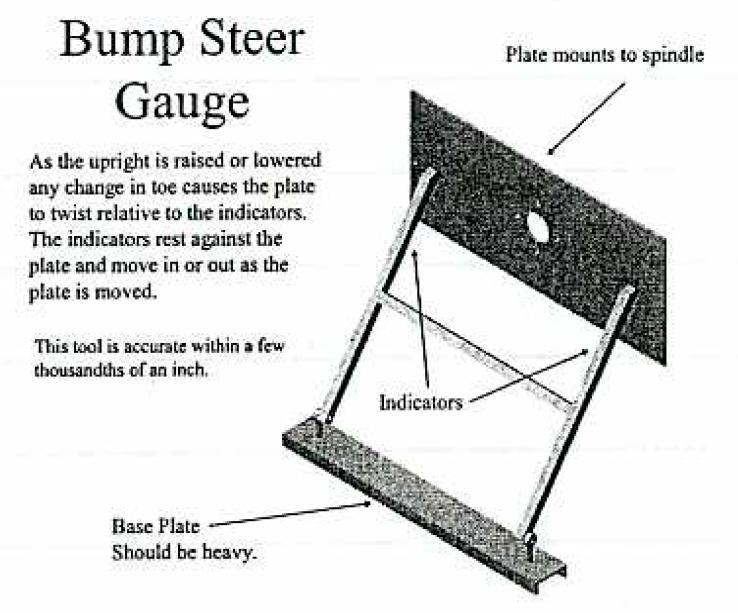
Sure, attached is a diagram. I won't have a real pic until mine comes back. Credit has to go to Brabham. The design comes from the manual for the BT-18. The other cool thing I need to build is flag alignment system. Cary
-
Cross Member Bump Steer Mod
tube80z replied to Twoeightnine's topic in Brakes, Wheels, Suspension and Chassis
Jon, that's a really slow way to measure bumpsteer. It's much better to use a simple system of a heavy weight at the bottom, two cheap heims, and a simple fabricated H. The bottom legs of the H are hooked to the weight. You put a toe plate on the wheel and move it up and down the amount needed (I used spacers under the wheel to make this go quicker. No dial indicators are used, you simply eyeball the gap front and back. Make a change and repeat. If you're really anal and want to meausre it you can use feeler guages. Not only is this cheap but you can do a corner in about a quarter of the time. Cary -
No, the issue isn't the pin (bolt), it's really what's the best way to resist bending at this point. Few people will ever see this as an issue unless they use the car rally hard on a track. A better way to resist bending is to use a solid rod end and a wider spacing for the mount. Just adding a lower dog leg to the standard clevice will generally keep the bending from happenning. You don't want to put a heim in this location as it will allow an addition degree of freedom. Once you overcome the forces putting tension on these parts from car weight you will get a wheelbase/caster change. In practice this is seen as severe wheel hop under braking. Double lower balljoints can be done but you have be careful how things align. Cary
-
Front Suspension Swap question
tube80z replied to Careless's topic in Brakes, Wheels, Suspension and Chassis
I went and looked at the pics. One thing you need to be aware of doing this conversion is that you're steering geometry is going to have issues. Look at the angle when the steering arm is in rear steer mode and then look at the angle it is on front steer mode. It looks to me like you now have an anti-ackerman mod. Are you doing this to get a two piece strut or better brake options? From a geometry standpoint I don't see this as an upgrade over the Z strut, unless I'm missing something. I'm very curious though. Cary -
It would be better for anyone making these to stop using a clevice. It's far easier to bend where the clevice is than if you use a solid rod end and a double shear mount. My old race car used arms like these and I could bend the dog legs from time to time (braking and jumping FIA curbing). A double shear mount with the clevice stopped this but then I have an extra piece that's a waste. I'd be careful to think about using flat steel for the LCA. With sway bar loads you've introduced an undamped spring. Is it an issue? I don't know. Cary
-
Actually you need to do more than that. The caster trail needs to be adjustable to be able to use the large caster angles are different size tires and make this work. How about integrating the dog leg into the LCA and alinging it to the lower balljoint. Cary
-
Q about control arm design (non Z related)
tube80z replied to J__'s topic in Brakes, Wheels, Suspension and Chassis
There's a lot of good advice above. It's really hard to give any specifics for an open ended question, with little info on how the car will be used. A few things to think about. Most of the software out there doesn't calculate the RC correctly. When you enter numbers for roll it simply moves the car on the centerline and calculates how the RC moves. There's a good reason for this but it can lead to misleading results. RCs move in three dimensions and most of the software doesn't take that into account. And none of the packages that I've seen (cheap ones anyway) allow for compliance in the bushings or the linkage. If you do come up with a design it might be interesting to see what happens on the computer if you move things around an eigth of an inch or so. Sometimes the results are interesting and will lead you to make parts much stiffer in some dimensions. The best advice I could give is don't get to wrapped around a particular RC height or trying to control its movement too precisely. As stated above try and determine what the tires need from a camber point of view and use that to let things fall where they may. It may make more sense to look at changes to the slope of the curves that are generated. In my very limited experience keeping this more or less constant has made my car a little easier to drive. In general a above ground RCs will have car that reacts quicker and heats the tires more from the lateral scrub. You will have a net lift when you corner with a suspension like this. An underground RC will make a car react slower, which sometimes can be good, put less heat into the tires, and will lower the ride height as it corners. I'd try and keep my RC in an envelope that doesn't move more than 20% of the track width, doesn't cross the ground or a wheel during any high force manuvers. Some argue this is BS but again in my limited experience this has helped some stabilit problems I had. It would be best to create a design that allows you to at least change RC height as this is a key tuning tool. Hope that helps, Cary -
rear poly bushings on outboard end of CA
tube80z replied to blueovalz's topic in Brakes, Wheels, Suspension and Chassis
Unibits are great for this kind of thing, even the cheap HF versions. Although Costcos cut much better. Cary -
any pic of "slotting the strut tower"
tube80z replied to Rebird's topic in Brakes, Wheels, Suspension and Chassis
We autoxed for years that way with no issue using the isolator on top. I even drove my 510 that way for 5 years. Cary -
rear poly bushings on outboard end of CA
tube80z replied to blueovalz's topic in Brakes, Wheels, Suspension and Chassis
Yes, if the ball pops out you may lose containment. Most sanctioning bodies require safety washers for single shear mounting. I figure it's cheap insurance you hope to never need. Cary -
rear poly bushings on outboard end of CA
tube80z replied to blueovalz's topic in Brakes, Wheels, Suspension and Chassis
The only thing I could think of might be to use spacers to change the side to side track width either to tune balance, square the car up, or get the strut tube fore/aft angle equal. I guess it depends on how precise you want to be on setup. I would recommend a safety washer on the outside of the heims. Cary -
PICS: Custom rollcage fabrication/install
tube80z replied to mull's topic in Brakes, Wheels, Suspension and Chassis
Looks very similar to what I did on my tube car. I have a book from Japan that is a history of racing Zs. I'm pretty sure I have some of these pictures. I can't read any of it but it's fun to look at what they've done. Cary -
Typically rebound forces are higher than compression forces on the shock shaft. Welding a gap is a really great way to make a weak joint. If you have a gap use tubing on the outside to bridge and weld this up. That's the correct way to do this. Cary
-
You missed a very important one. TLA -- three letter acronym. Cary
-
I guess technically it didn't fail. As the car left the road it hit a tree left in the side. I've attached pics below. What you can't see from the pics is the car rolled onto the tree and the weak spot was the rocker, which had no tube running along it. It folded in along with the floor breaking the drivers leg/hip in multiple spots. The door bars where nascar style and you can see how folded they are as well. This car was a beast and left the road a very low speed comapred to what it could have been going. If the bottom of the rocker had been reinforced I think the driver would have been able to walk away. Cary
-
rear poly bushings on outboard end of CA
tube80z replied to blueovalz's topic in Brakes, Wheels, Suspension and Chassis
The adjuster I'm thinking of is a shell. On the outside is a set of threads and on the inside is another. One set are right, the other left. This allows the unit to operate like a turnbuckle in a very limited space. The toe-adjuster was shown on another pair of fabricated arms in one of the threads where rear arm options were discussed. Hope that helps, Cary -
rear poly bushings on outboard end of CA
tube80z replied to blueovalz's topic in Brakes, Wheels, Suspension and Chassis
No, by toe-adjuster I'm talking about a specific piece that has left/right threads sorta like a turnbuckle. I do agree once this is set it isn't that likely many people will be changing it. Cary -
rear poly bushings on outboard end of CA
tube80z replied to blueovalz's topic in Brakes, Wheels, Suspension and Chassis
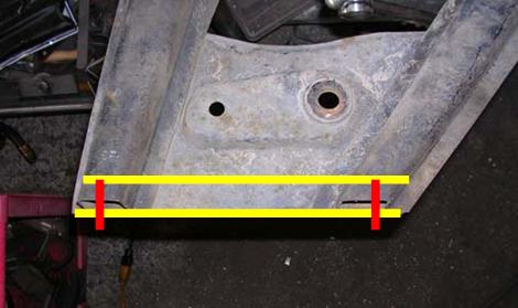
The adapters that John has will be stronger if they are held in a couple of places. I think they could be welded into the stock arms. The tube idea was to simplifiy the fabrication and make the arm stronger. It's a lot easier to use a holessaw on square tube and mount the adapters and then weld this assembly to the arm. In the pic below the yellow bits are square tube and the red bits the adapters welded into it. You can see how this part bridges the tubing of the stock arm. If you use a toe-adjuster or better yet a threaded bushing with left/right threads you have adjustement on the car without taking anything apart. Cary
-
That's pretty close. The 8500 limit was for an L24. And as Paul mentioned it wouldn't hack much beyond that wihtout becoming two pieces. We even tried the nissan comp forged crank and had similar results. The ultimate solution we went with was to drop the rev limit to 8250 and call it good. When we switched to an L28 we called nissan comp and they indicated 8K would be about the max. So we went to 7800. The generall warning sign of a broken crank was a clutch pedal that jumped when you pushed it in and the flywheel would fall off when you took the motor out In almost all cases the front pulley bolt could be removed by hand after this happenned. If you lose something on one end the other takes a serious beating. Cary
-
The other news is the 8611-1259 double are now supposed to be digressively valved. Cary
-
The other news is the 8611-1259 double are now supposed to be digressively valved. Cary
-
rear poly bushings on outboard end of CA
tube80z replied to blueovalz's topic in Brakes, Wheels, Suspension and Chassis
I have some arms I'm going to eventually modify for a friend. I was looking at them last night thinking about ways to do this. I thinking I'd cut the arms across the flat plate and weld on a piece of square tube. This tube would be hole sawed to hold the heim adapters Jon showed further up the thread. Not sure that makes sense but it's clear in my head Cary -
Mustang IRS? kinda long and rambling
tube80z replied to Chaparral2f's topic in Brakes, Wheels, Suspension and Chassis
I race wtih a guy that uses this setup in a pickup truck, an extremely fast pickup truck I might add. He's running similar levels of power and using sticky tires. He's not had any problems with axles but has blown up a number of the LSD units. As far as dragging the tail that will have a lot to do with the geometry of the suspension. You'll probably need to build in some anti-squat. Cary -
240Z Autocross Suspension Setups (all-out)
tube80z replied to zredbaron's topic in Brakes, Wheels, Suspension and Chassis
Hi Mark, Here's an old thread with some info that may help you. One big item to think about is tires, will you run slicks in prepared or a street radial for SM. That will make a difference in picking rates to go with. For let's start from the beginning: 4) car set-up as per John Coffey: Camber - 3 degrees neg front and 2.5 neg rear (fine tune with pyrometer). Some tires need more insided temp to work correctly but in general will be 10 to 15 higher (slicks) and may be even higher for radials. Caster - 6-8 in front (you can decrease camber if you have more caster) General rule of thumb is one half KPI (steering axis inclination). When running this much caster you also need to check to make sure you don't have too much caster trail (mechanical trail). You'd like to have around half an inch. Also try to have no more than 20 percent of tread width as scrub. Toe - 1/4 to 3/8 out in front and 1/16 to 1/8 in in the rear For tight track try rear toe out. Ride Height - 4.5 to 5 inches at the rocker (don't try to over lower the car) Springs - 400 all the way around (ideally should be set based on scale weights and multiplier for tire type -- perhaps another discussion). You'll need proper shocks to make this work. Helps to quicken transition times and keep suspension geometry for going all over the place. Sway bars - 15/16 to 1-inch front and 5/8-3/4 rear -- both need to be adjustable and connect to the strut, not the control arm. Sway bar should be in a low friction mount, which is not poly or other form of pinch block. Ideally at least one is driver adjustable for when you need to make the last minute tweak between runs. See what Jon has been doing for an idea of a low friction mount. Offset bushing - yes Will be needed for street prepared but should be avoided in other classes. Never use Poly suspension bishings, it has too much friction. These need to be low friction pieces to help with mechanical grip. Good advice on notes deleted(lookup the original thread). A tire pyrometer is good to indicate wear but not a lot more. But tire pressures are more accurate on how the tires are used. You should work on a setup that gives you an even rise in pressures. This is where good notes and understanding what you need for a hot tire pressure is important. You can switch to nitrogen to help eliminate the effects of water vapor in the tires. To adjust chassis balance you can change the rake. Rule of thumb is two turns of the spring collar to start. If the effect is too much try one turn. You lower the end that isn't sticking. Make sure you keep the arms near lever and don't end up too low. The car should be corner weighted. Make the front level and the front weights as close as you can and live with what you get in the rear. Move as much weight down and towards the back as you can but not behind the rear wheels. Remember you need to make ride height changes to compensate for weather conditions to keep a balanced chassis. Also consider using shims for camber/caster plate alignment. These allow rapid known changes and/or allow you to get the car put back together without having to do a major alignment. Before an event always know all your settings. Keep notes of any changes that you make at an event. And at the end of an event do a setdown. This last step is important and few people do it. If you're using the same size tires all around keep notes on how hard they were used and rotate to keep the use as close to the same as you can. Do all chassis setup work on old tires (but not junk). New tires will mask a lot of the changes until you have killed them. By doing all this you'll end up having a car that is kinder to its tires. A number of assumptions have been left out of this thread, like bumpsteer, corner weighting, checking for compliance, suspension binding, etc. Test, test, test, and have lots of fun. Hope this helps, Cary