NewZed
-
Posts
6700 -
Joined
-
Last visited
-
Days Won
72
Content Type
Profiles
Forums
Blogs
Events
Gallery
Downloads
Store
Everything posted by NewZed
-
Machining Bell housing for S13/14 5 speed swap
NewZed replied to 1976 280Z's topic in S30 Series - 240z, 260z, 280z
Which of the three operations are a problem? The shift rod hole enlarging and the clearance work for the gear are fairly easy. The enlargement of the bearing hole requires more accurate work. If you swap to the smaller bearing, you don't need that. Most machinists pause at the bearing hole work. Xnke has a trick for that but may or may not share it. -
Good luck. You've only defined one "problem" and it doesn't seem like big deal. Idle AFR is a bit rich, but everything else is correct.. Here's a decent reference. It's Megasquirt and you don't have the tuneability, but since you're only worried about idle you could open up the idle air adjustment screw on the AFM. Described in the Engine Fuel chapter of the FSM. "Batch fire engines, however, have issues at idle with intake pulse reversion sending some of the fuel into an adjacent cylinder. So, if your engine is batch fire, you'll need to add a little more fuel so all the cylinders can stay at 14.7:1 or richer. Batch fire engines typically idle best in the mid 13's, so if you're leaner than that, put in some more fuel and see if that stabilizes the idle.:" http://www.diyautotune.com/tech_articles/megasquirt_idle_tuning.html
-
Idles rich, or drives rich? Rich as defined by an AFR number? "Correct" means that resistance matches temperature as shown in the chart? Or it means "continuity"? Testing was done at the ECU connector or the component? The temperature sensors don't "output" anything. Numbers are your friend when working on the EFI system. Numbers make a big difference on the forums. Without numbers you're just part of the herd.
-
http://www.nicoclub.com/FSM/240z/1972/FE%20Fuel%20and%20Exhaust%20Systems.pdf
-
So there is a silver lining to all of those blue Subaru clones out on the streets. Seems a little down on power capacity though. Weaker than factory, isn't it. Shouldn't be spec.'ed in HP anyway. Product Description This is for you guys installing a R180 from a STI in what ever you can get it under. This stub is a 300m part capable of over 100Hp and ready to have a 108mm CV bolted up to it. http://www.roadandtrack.com/new-cars/car-comparison-tests/reviews/a6306/2015-subaru-wrx-vs-sti/
-
Sectioned Struts - Need spacer for the shock
NewZed replied to konradlip's topic in Brakes, Wheels, Suspension and Chassis
Which one? - http://dupont.materialdatacenter.com/profiler/7MblW/standard/main/ds Just kidding. Kind of. Most thermoplastic polymers aren't suitable for constant high loads. They "creep". The fine threads of the gland nut put a pretty high load on the shock and spacer with any appreciable torque. If you cut your spacer so that it contacts the shock body via a sharp corner or small area, that area will deform easily. Add some heat and things get worse. Just something to be aware of. Get the design right. http://www.dupont.com/products-and-services/plastics-polymers-resins/thermoplastics/brands/delrin-acetal-resin.html Easier to go wrong than right with Delrin, in that application. -
Injectors not firing, no power. Bad ecu?
NewZed replied to Trystan_lake's topic in S130 Series - 280ZX
The ECU just reacts to what Pin 18 does. When the coil discharges, the voltage pulse on Pin 18 makes the ECU ground the injector circuits. So if you're getting spark and Pin 18 is connected to the coil negative terminal, something's not working right in the ECU. -
Injectors not firing, no power. Bad ecu?
NewZed replied to Trystan_lake's topic in S130 Series - 280ZX
All of those "good"s just mean maybe. Why didn't you write the numbers down? The ECU grounds the injectors when it sees action on a certain pin at the ECU, which is connected to the coil's negative terminal. Which is also connected to the ignition module. Maybe you disconnected a wire by accident. The module you replaced is the matchbox on the side of the distributor, right? And you said no power, implying at the injectors, but didn't say that you actually tested for power at the injector plugs. I would check for power at the injector connections, and confirm that the trigger wire to the ECU, the one connected to coil -, is intact. Unfortunately, there aren't any good wiring diagrams for 1983 that I know of. It's a difficult car to work on. 1982 might be the same. Worth a shot. Looks like Pin 18 at the ECU should be connected to coil -. http://xenonzcar.com/s130/images/wiring/1982%20Datsun%20280ZX%20non%20turbo.pdf -
Sectioned Struts - Need spacer for the shock
NewZed replied to konradlip's topic in Brakes, Wheels, Suspension and Chassis
Delrin would probably creep or deform and you'd lose your gland nut torque. Metal's a better option. -
If you don't have a meter, a test light will do. Anything besides just turning the key and wiggling wires. Measure the power paths (aka crcuits) and see where the break is. First confirm battery voltage across the posts themselves. Then across the cable terminals attached to the posts. Then the cable ends at the starter. Starter lug to engine block. Starter lug to body panel. Things like that. You're not even using the most basic troubleshooting method.
-
Need some opinions on rear half shaft route with R200 VLSD
NewZed replied to seattlejester's topic in Drivetrain
The auto parts store guys will usually pull a CV shaft out to let you look at it. Awkward phraseology... -
He installed adjustable control arms at the same time. So, still undefined. Just saying, make sure. Also, it's not clear how the kit works with bolt in R180 axles. How do you attach that adapter to the splined shaft? I don't know the R180's very well though, so maybe it's obvious. Or maybe you need the truck diff. A phone call would probably clear it up.
-
Got a meter? Measure resistance of the cable. Measure secondary circuit resistance with the cable inserted in the coil. Seems like you're stuck on some pretty basic stuff.
-
Ermish looks new to the scene. A 510 guy getting in to the Z market. Better be careful on length, there are no signs on the site that he's actually used those axles in a Z. Improper length is where everyone gets burned.
-
Z31 ECU MAF upgrade for L28ET 78 280Z
NewZed replied to rickyellow zee's topic in Turbo / Supercharger
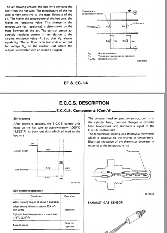
Actually, you'd want to know how many amps the ECU lets pass through the wire. There might be resistance on the ECU side and 12 volts direct from the battery might just burn the wire up. But if there is resistance on the MAFS wire then it's probably controlled there and a switch would work. That speed sensor controls other things also though, like fuel cut during deceleration. Without fuel cut, you'll get the gassy smell. Kind of defeating the purpose of a more modern system. Look through the EFEC chapter and see how many things have "speed sensor" as a control parameter. Actually, there's a table on EFEC-33 (1987) that shows 4 things that use the speed sensor. -
Z31 ECU MAF upgrade for L28ET 78 280Z
NewZed replied to rickyellow zee's topic in Turbo / Supercharger
This may be why so many people seem to get this swap "almost right" as far as the way the engine runs. A bunch of dirty MAFS wires out there. -
Z31 ECU MAF upgrade for L28ET 78 280Z
NewZed replied to rickyellow zee's topic in Turbo / Supercharger
Here's the two side-by-side. Same parameters, just a better explanation.
-
Z31 ECU MAF upgrade for L28ET 78 280Z
NewZed replied to rickyellow zee's topic in Turbo / Supercharger
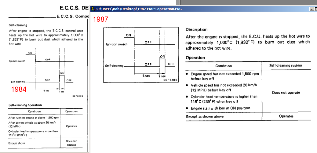
This is interesting. Nissan rewrote the chart for 1987 MAFS self-cleaning operation. Don't know if the chart was wrong or they changed the operation parameters. I'm guessing that the 1984 chart was wrong and/or confusing. You didn't say which Z31 you had so you'll have to draw your own conclusions. Looks like the basic design is that it cleans the wire as long as three conditions are met - engine speed went above 1500 RPM, vehicle speed went above 12 mph, engine not overheating, and engine shut off normally. As soon as the engine is turned off, it waits 5 seconds and cleans for one second. So it looks like you need the speed sensor if you want the self-cleaning to work.
-
Z31 ECU MAF upgrade for L28ET 78 280Z
NewZed replied to rickyellow zee's topic in Turbo / Supercharger
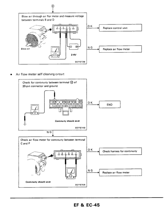
I think that the diagram and test description imply that the ECCS sends 1 second of power through Pin 12 of the 20 pin connector which then passes through pins C and F of the MAFS, to ground. But it may not be full battery voltage so a switch may not work. Best to let the ECCS do it for you. Basically, Pin 12 needs to be connected to either pin C or Pin F of the MAFS. That wire 33 is probably connected to one of those. But it's unclear from the chart if all three conditions need to be met or just one. Looks like all three but who knows. So your question about if you need the speed sensor is still open. -
Z31 ECU MAF upgrade for L28ET 78 280Z
NewZed replied to rickyellow zee's topic in Turbo / Supercharger
Actually there's still some figuring to do, but that should get you closer. -
Z31 ECU MAF upgrade for L28ET 78 280Z
NewZed replied to rickyellow zee's topic in Turbo / Supercharger
Should be enough in these two pictures. Either use the ECCS wire, or hook up a switch and count - one one thousand.
-
Works now. Take the distributor out and see if the drive shaft, bottom of the hole, is connected to the crankshaft. If it turns freely by hand, you'll have to remove the oil pump. Apparently the shaft can slip down inside the drive gear. Another Hybridz member had that happen. So you might find that the shaft won't turn, but the tang doesn't stick up far enough to catch the distributor. You might also find that your distributor is about to fall out and has lifted up out of its mount.
-
Tried ti reply to this before and it wouldn't post.
-
Need some opinions on rear half shaft route with R200 VLSD
NewZed replied to seattlejester's topic in Drivetrain
Actually, the guy that welded the shaft may not have tried it out. #13 - http://forums.hybridz.org/topic/112092-j30-shortnose-vlsd-into-open-longnose-r200/ Found the original too - http://forums.hybridz.org/topic/110563-nissan-vlsd-into-a-long-nose-r200-axle-options/ -
Need some opinions on rear half shaft route with R200 VLSD
NewZed replied to seattlejester's topic in Drivetrain
Can't remember who it was but a Hybridz member extended the inner portion of the shaft that needed to be long by cutting and welding on another splined section. It's all torsional inside the diff so the flexing and stress riser issues you'd see on the outside seem diminished. He said it worked fine and hasn't been back to report a failure so who knows. Welding the shafts affects the carbon content of the steel and the heat-treatment. Most shops don't like to do it so you'd probably have to waive your right to complain if you had flanges welded on the outside.