NewZed
-
Posts
6700 -
Joined
-
Last visited
-
Days Won
72
Content Type
Profiles
Forums
Blogs
Events
Gallery
Downloads
Store
Everything posted by NewZed
-
The numbers don't support the need for a new pump. They are are correct for no boost. Not clear. That's all I'm saying.
-
Parts found lying around usually are there for a reason. Does the 1991 325i 5 speed even have exceptional value? What would be the benefit? I've driven a BMW stick shift, 1984 325i, and the lever action is rubbery and mushy. Didn't like it compared to the plain old ZX 5 speed.
-
I meant learn more stuff. "Or something" means that you "don't know". 7.4 psi (15 inches Hg) of boost plus 36.3 psi ambient = 42.7 psi. That's maximum fuel pressure at maximum boost. Not WOT with no load. No boost, max. pressure = 36.3 psi . Or ~38 depending on which book you're looking at. Some FPR's run a pound or two high, so 38 psi is common. The 1983 FSM is pretty bad, so good luck. There's nothing in there about 44 psi though. stupid_fast was right, give the engine a better tune than new cap and rotor. You're kind of spinning your wheels, and about to replace good parts, without a general systems check.
-
Red-Blue wire grounding? Need help with routing.
NewZed replied to Naamiokostaja's topic in Ignition and Electrical
Here's a diagram showing some red-blue wires. A few things to check, like the reverse switch (it's surprising how unprotected and dirty that area is on the transmission. Seems like more shorts would happen there), inhibitor switch, blower motor, etc. http://www.atlanticz.ca/zclub/techtips/wiringdiagrams/240z/1970_240z.gif -
-
5.3/T56 swap noise--video inside
NewZed replied to ukcats07's topic in Gen III & IV Chevy V8Z Tech Board
Sounds like an exhaust leak. Why would you be looking at your slave cylinder? You said it doesn't change with clutch actuation. -
T56 will not go into any gear
NewZed replied to Old Man's topic in Gen III & IV Chevy V8Z Tech Board
You should retitle your thread as "LS1/T56 clutch disengagement problems" or something like that, and add more detail on the clutch parts. Maybe your .875 bore master isn't right for the "stock" slave cylinder. "Stock" for what, for example. Anyway, there are few guys on here that have been deep in to their LS1 clutch problems. You just need to catch their eye. Edited out my confusion on "slave cylinder". -
2005 Subaru R180 LSD swap into 75' 280z with oem r200
NewZed replied to 280Z-75's topic in Drivetrain
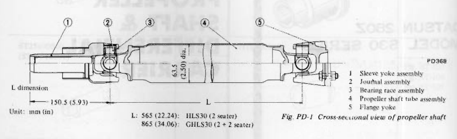
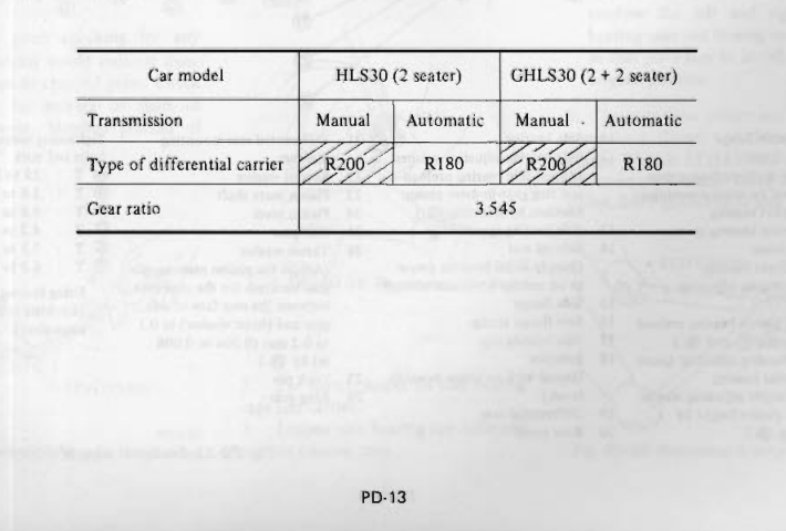
1975 280Z's have the oddball R200 pinion flange. It has its own unique bolt pattern and bolt size (might be the same as the 300ZX's, not positive. Definitely not like the other Z cars though). So if you cut a 1975 R200 driveshaft, it's only good for 1975 R200's. Beware the 1975 R200. And the R180 pinion flange location in the car is not different than the R200 (I've never had an R180 but all signs seem to show this). You can swap an R180 for an R200 and use the same driveshaft. Except for the very early 240Z's with the forward-mounted diffs, that use a shorter driveshaft (which is usable with the 240SC/71C swap though, except 1975 cars). A good general reference - http://www.zhome.com/ZCMnL/tech/R200.htm And a couple of excerpts from the 1978 PD chapter.
-
Stumped by engine bogging.....1976 280z coupe
NewZed replied to lorenzo's topic in S30 Series - 240z, 260z, 280z
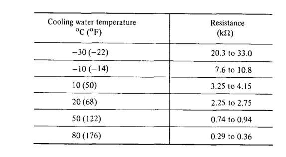
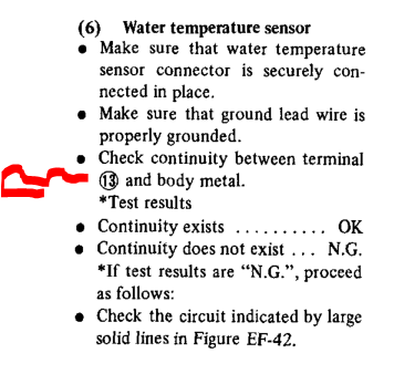
Have you measured resistance of the coolant temperature sensor circuit at the ECU connector and compared it to the chart? How do you know the new one is even connected to anything?
-
Stumped by engine bogging.....1976 280z coupe
NewZed replied to lorenzo's topic in S30 Series - 240z, 260z, 280z
Does this mean it runs well cold, then runs poorly after it warms up? There's no time-frame to work with, besides "starts out driving" and "then a short time later". -
Finding a Clutch Master that is Right
NewZed replied to Klmykvl's topic in S30 Series - 240z, 260z, 280z
Swap rods. -
Did you try turning up the idle speed screw? Don't know what carbs you're using but most have an idle speed adjustment. More ignition advance typically increases idle speed. Could be that all you're really doing with your timing adjustment is increasing idle speed. Gotta start somewhere. On the cam - can you see anything like that shown in the attached picture? With the straight side of the chain tight.
-
Here's a write-up for the 280Z thermostat temperature sensor. The CHTS does the same, from a different location. http://atlanticz.ca/zclub/techtips/tempsensorpot/index.html
-
Mid to late 90's Honda and Mitsubishi SUV's have a metal inline Schrader valve that you can cut out and T in to a rubber fuel hose. If you're by a wrecking yard. Just leave it in. You said you wanted ideas to try while you waited to get a gauge. The potentiometer can be slipped in between the two bullet connectors on the CHTS circuit. Zero hacking required, completely reversible.
-
Doesn't Comp Cams supply instructions? Most cam grinders keep the original reference marks. #1 should work. You didn't say anything about carbs or EFI or Megasquirt. Could be that your problem has nothing to do with cam or ignition timing. Or your damper timing marks are off.
-
Here's a good reference for brake options. If you're going to do it, might as well get it right - http://forums.hybridz.org/topic/38499-brake-upgrade-faq/
-
You're using poorly setup stock parts as a reason to replace them with expensive non-stock parts. This is how budgets blow up. Anyway, the thread has deviated in to philosophy. You'll find plenty of opinions on the forum to support spending money. Good luck.
-
That wasn't the point. Many of the older stock systems, for whatever reason, run lean with stock parts in good working order. The potentiometer lets you add a little bit of fuel over the full fuel curve. It's a simple tuning aid, not really a fix for a bad part. But, of course, measuring fuel pressure so you know what you're actually working with is the best idea. If fuel pressure is fine, do the potentiometer. This is the common lean AFM symptom - "Taking it on the road, with more than 15-20% throttle applied it would stumble, sneeze, and front fire very harshly."
-
I was just trying to show that you're making decisions on very little actual knowledge. Like the statement above - the car already has power (booster-assisted) brakes. If you meant "more powerful" there are numerous threads that talk about how the stock brakes work fine and are balanced correctly for the car, when they're in proper working order. And numerous threads talking about how the "upgraded" Toyota brakes, and rear discs, are biased to the front. You asked for suggestions. I say read more, take everyone's advice with a grain of salt (people inherently defend decisions that they've made. Objectivity is hard), drive the car for a little while, and make decisions based on a clear view of how you want the car to behave.
-
"Bigger brakes" in your first post was the clue. You haven't studied enough to know what's what. You're on the bling path. Form over function. All good, just that your plan doesn't fit your stated goal.
-
Many people, those that have done it especially, feel that Megasquirt alone is an upgrade, even on a stock engine. The 70's cars were surrounded by carb'ed cars so the EFI seemed clean and efficient. But compared to today's EFI systems, the old EFI is clunky, dirty, and problematic. But until you drive one, and compare it to a modern EFI car, like a Pathfinder or Buick, you won't really know.
-
You should wait until you have the car, and think a lot more about what you want it to be. You just have a list of random things to do, but they don't really fit together to make a better car. Pretty easy to spend a lot of money and just make a Frankenstein monster. Weird-looking and doesn't work well. You can't really upgrade anything until you know what "better" is. By the way, these are 240Z shocks. Only two of them will work in your 280Z. http://www.amazon.com/KYB-FRONT-REAR-shocks-struts/dp/B002T4HDY6?tag=viglink20591-20 You want these. If you want stock style. http://www.amazon.com/KYB-FRONT-REAR-shocks-struts/dp/B002T037EK
-
You said heat soak, vapor lock, and heat issues but didn't really describe what happens, or when. The typical problem seems to come from hot injectors. Running the water pump and fuel pump would probably help. But you'll be using your fuel as a cooling medium. Many people have had luck by just installing an aluminum fuel rail. But you probably already have one of those. Wrapping the rail might make the problem worse since it won't allow the rail to radiate heat away from the injectors. If your heat shield is missing that will make the problem worse. Nissan spent a lot of effort trying to keep heat away (shields) or remove it (fans) from the fuel lines. Sounds like you've deleted both of their fixes.
-
Extend the fuel rail return line in to the cabin and run it under your foot so that you can press it closed as you drive. More foot pressure = more fuel pressure. You could also put a potentiometer on the CHTS circuit. Turn up the resistance to get more fuel. The AFM's tend to get lean as they get old for some reason.
-
5.3 wont start could it be the ignition??
NewZed replied to milesz's topic in Gen III & IV Chevy V8Z Tech Board
"On" typically means the "Run" position. "Start" typically means the position to send power to the starter solenoid and turn the engine over. "Trying to turn it on" could mean either. You can get clicks in both positions. Have you measured voltage anywhere? At the battery, at the starter? Get a meter and measure some stuff. Could be a dirty cable connection.