-
Member Statistics
33108
Total Members2821
Most Online
All Activity
- Yesterday
-
 Spoke to Mike Maier today seeing as the front suspension is most similar to that of an old Mustang. I wish I could write notes faster because holy hell that man is a wealth of knowledge. Suggested the reason for high spring rates is to prevent the upper control arm from camming over (poor arm design) and that the 3.5" of travel is definitely not enough for a road racing/track car (burms). Looks like my next steps are installing an adjustable upper ball joint that can move up/down to change the coilover angle and shock pot it at ride height looking for the lowest load value. If no substantial gains can be made there it's either back to the drawing board to make a push/pull rod cantilever or cut out the shock towers entirely and try to copy MMI's own Mod 2 strut tower modifications as well as new control arm(s) to gain the ability to mount a full length shock to the lower wishbone. This is becoming more and more of a fully custom project by the day.
 -

TR's 260z L28 Build Thread
TrumpetRhapsody replied to TrumpetRhapsody's topic in S30 Series - 240z, 260z, 280z
Tisk, late again! Back in early June I took the plunge and ripped out MS2 and EDIS, to completely rewire for MS3 Pro Mini with LS3 COP, a dedicated relay box, flex fuel, dizzy signal from a Jeep CAS for sequential fuel, and more sensors. I ran into some interesting issues. On the MS3 1.6 firmware I found a bug where Fan Control would not work properly on the PWM-Idle output, so I had to run 1.6.2 beta2. Oddly, having swapped to directly feeding MS3 from my crank VR sensor (instead of EDIS), triggering the fan was causing a phantom RPM signal to fire the injectors and coils thinking the engine was starting. I suspect my troubleshooting of that may have fried the firmware on my LC1, so I ended up upgrading to an LC2 which reads much smoother! I still need to figure out what's causing that, but so far I'm not seeing noticeable effects when the fan kicks on and the engine is running. To get my E85/Flex going I still need to cut bend and replumb my engine bay fuel lines through the new sensor, and I haven't wrapped the harness so no pics just yet. Eventually I also need to modify the Jeep CAS to fit the L28 slotted drive so I can get going with sequential. Still, it's running so much smoother on semi-sequential rather than batch mode. The AFR and fuel pressure safety features are also a godsend! -
What is your Rear End Gear Ratio? You probably should be running 4:11 or lower. Also, what size slicks do you have?
-
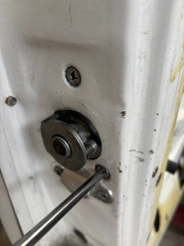
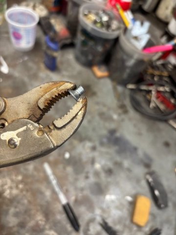
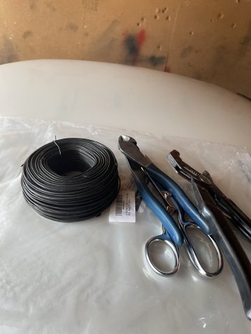
A simple solution for door slamming problem? I finally finished my 8.8 Super Duty 8.8 Differential Conversion so I had time to handle all those small detail work. During my restoration work, I used Precision Weather Stripping to my worn OEM ones. But the Precision Weather Stripping always seemed too stiff for its job. So anyway, I gave them about 4 months but still had to slam the door to seat the weather stripping. It never got better so I know some members used late model KIA weather stripping from Amazon and good results. So I tried the Kia weather stripping. It was a lot softer but still had to slam the door. I decided to remove the Door Latch and study its operation. After removing it, I cleaned it and lubricated it with White Grease. Everthing seemed tested fine when it was out of the car. But after installation, the problem was still there. The Door Latch seemed like it still needed a little more inward movement to function properly. So with the Door Latch installed, I watched the Locking Mechanism operation. As the Door Glass was not installed yet, you have a good view of the Locking operation. this is when I noticed that one of the Latch Mounting Phillips Screws( 6mm x 1.0) was hitting the Linkage. This Screw is 4MM too long. The Easy Solution was to cut off about 4MM of the threaded end of the screw. Pic of the Long Phillips Screw-Inner Bottom Mounting Latch one. ". , Pic of "Corrected Phillips Screw" I really don't know when the Phillips Screw is mistakenly replaced with a Longer One. Owning the 240Z for 54 years, I am sure I removed the Door Latch at least 4 times. Anyway, if you having Door Slamming Problems, check the LATCH MOUNTING SCREWS. It was a Simple Solution for me, maybe for you, too.

-
Update From Apex: Front • Motion ratio: 0.92 : 1 (wheel : shock) • Wheel rate: 0.92² × 600 lb/in ≈ 510 lb/in • Wheel travel with 3.5" shock stroke: ≈ 3.2" Rear • Rocker motion ratio: 1.00 : 1 • Wheel rate: 700 lb/in • Wheel travel with 3.5" shock stroke: 3.5" Some confusing design and hardware choices here. Using a bellcrank/rocker with a 1:1 motion ratio doesn't take full advantage of the system. I will end up designing and having manufactured a new billet bellcrank/rocker with a lower motion ratio to get more shock travel. Highly likely I'll source a Hyperco spring at a different rate but that'll be handled during the bellcrank redesign and is a straight forward task. The front axle is giving me some headaches. The lack of suspension travel could be fixed by adding a bellcrank/rocker, but there isn’t enough space to fit one between the top of the strut tower and the hood. Making room would require major cutting and fabrication to the strut towers. Mike Maier Inc.'s solution to a similar problem was to completely replace the original shock towers with a custom design, allowing a full-length shock to mount higher and further inboard. On the Z, moving the strut tower further inboard could create enough clearance between the upper control arm to let a coilover mount to the lower control arm. But by that point, I'm only a few steps away from designing a fully bespoke 1:1 double wishbone kit, making the OTS kit a useless purchase. I've been drawing up some concept sketches on how I could possibly do a pull rod but that would render the OEM strut tower essentially useless. Alternative to implementing a front axle rocker would be to modify the upper wishbone where the bottom of the coilover mounts to be further inboard which would lower the motion ratio more but I'm not keen on trying that solution. I think I need a sanity check, I'm used to working on strut-type suspensions that have decently high shock travel to the point where coil-bind is a more pressing issue at low ride heights. Is there another solution to a short shock stroke and high spring rate I'm not considering? Or is this a case where the problem is all in my head and having 3-3.5" of shock stroke isn't that big of a deal? I've spoken to Rob Fuller from ZCarGarage regarding this problem who had some great insights on Z suspension, unfortunately he wasn't able to help me much past confirming that the wheel rates are ludicrously high. I'm aiming for a front axle wheel rate in the range of 300# to 450# and even then 450# still seems extremely high for the front axle.
- Last week
-
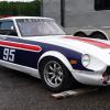
IMSA GTU vintage racer build
clarkspeed replied to clarkspeed's topic in S30 Series - 240z, 260z, 280z
I'm back! Sorry for the long delay on posts, family, work, and travel have sucked up time along with losing a laptop that had a large number of photos. I have restored most of the photos now and will try to catch back up. Polycarbonate windshield ready to mount, firewall extensions, and rear fender liner.
-
Those hairline rotor cracks are common when running giant rotors. Even though you are getting very little rotor wear due to the size of the brakes, the heat cycling eventually forms the cracks. I've ran them on track probably about twice as bad as your pictures.
-
zcarjunky joined the community
-
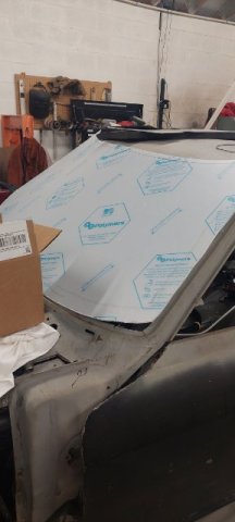
I was considering their hood and hatch replacements instead of patching mine up. Does anyone have any experience with those items?
-

A musician's therapist (The $300 Z)
Zetsaz replied to Zetsaz's topic in S30 Series - 240z, 260z, 280z
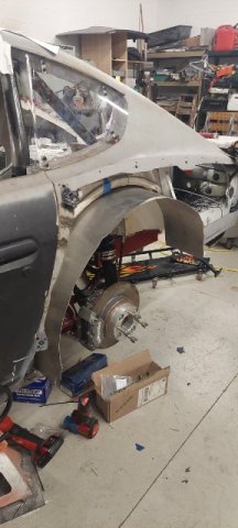
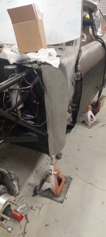
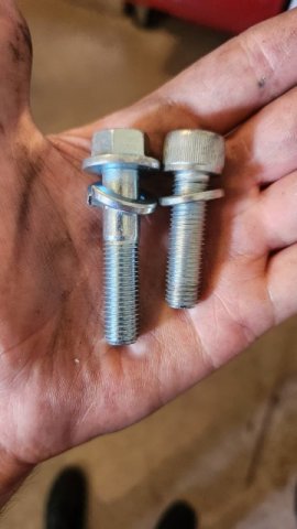
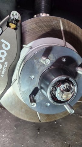
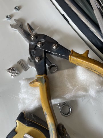
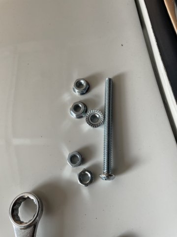
Small jobs today- Replaced that short hardware on the front rotors to hubs I mentioned in a previous post. Included Pic is the size difference. Brakes didn't feel particularly unsafe on my few drives around town, but always better safe than sorry with the most important things like brakes. Second pic shows how the new hardware actually goes all the what out to the wheel mounting surface to engage as many threads as possible Next small job before the correct rear brackets arrive is re-adhering a part of the headliner that is sagging a bit. I think the adhesive didn't cure properly when I installed it forever ago and the intense heat on the roof at one show made it droop. Only fix is to reapply but fortunately it's easy since the rest of it is already adhered well and lined up. Hardest part of the job is centering it
-
Hello, Are you using fresh fuel. Fuel will go off over time.
-
 chaidez10 joined the community
 -

My Z car log....small jobs done and fun things
A to Z replied to A to Z's topic in S30 Series - 240z, 260z, 280z
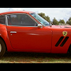
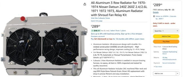
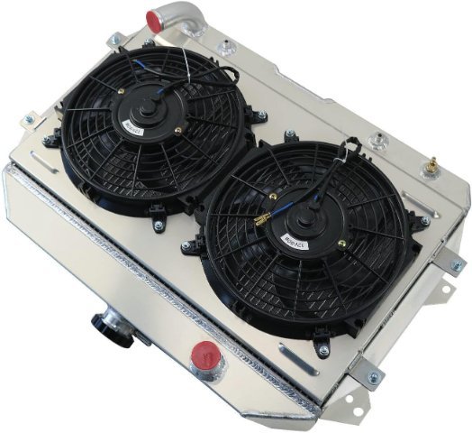
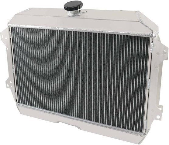
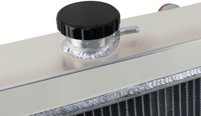
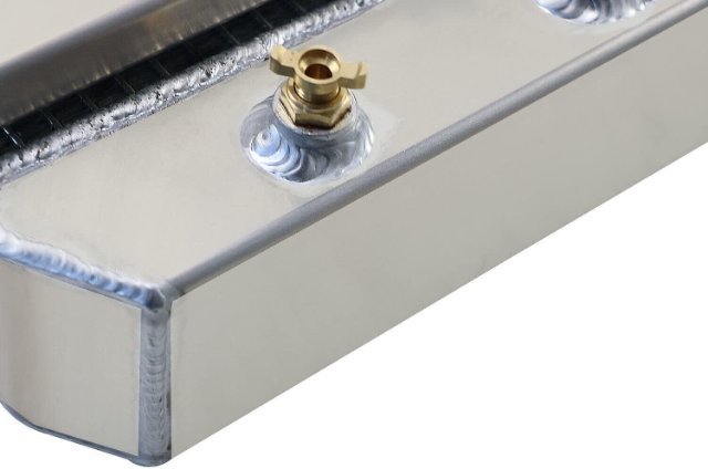
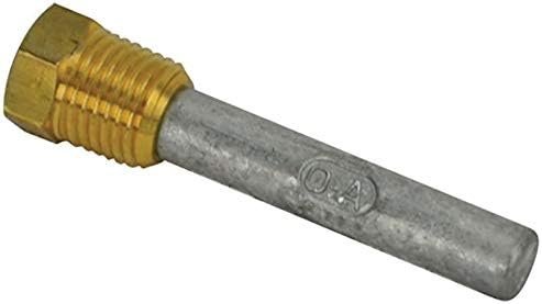
So, the heat issue has caused me to go ahead and order a 3 row aluminum radiator with dual electric fans. I decided to get one I found on Amazon, made by CB Auto - which is in CHINA. So, half price of others and looks to be okay. I also went ahead and got an anode made of zinc that screws into the drain petcock. This is what allows the minerals to attack it instead of the aluminum in the radiator. I also will be switching my thermostat to a 160 degree one I ordered. Since I have had good luck with the chinese parts I have used, we will do this. factory video, click here: https://www.amazon.com/vdp/048db201f503475ea5ee22731531c6e1?product=B0BQGTGGL4&ref=cm_sw_em_r_ib_dt_8D3hq5NBWLJy6
-
I have, in the past, placed the plug wires on my L28 280Z engine in reverse rotation order. #1 was correct but the rest were placed in clockwise rather than counterclockwise order. The engine started and ran but it ran terribly. Since I had only replaced the wires as a tuneup on an engine that ran well I knew immediately that I had screwed up the firing order somehow. It must have been running on only two cylinders. 1 5 3 6 2 4 1 4 2 6 3 5 In short, maybe doublecheck your plug wire placement. Good luck.
-
I have not tried bypassing the box yet, but that’s a good call.
-
A musician's therapist (The $300 Z)
Zetsaz replied to Zetsaz's topic in S30 Series - 240z, 260z, 280z
Small update from T3 - Called today about the bracket issue, and their service guy on the phone told me the new brackets would get shipped out today. While bleeding the brakes yesterday to get a head start on some of the work left so they'd at least be close I noticed some fluid dripping from the opposite side. After inspecting it looks like the flare for the -3 end on one of my hoses was cracked. I ordered some new ones myself since I don't know if it was an installation error, but it's just one more thing wrong with the rear end. Despite shipping today I know they might be getting it out late enough that it won't actually leave California until tomorrow. Hopefully by Thursday I have a driveable car again. Two weeks until I leave on a road trip -
Thanks, Tom, will add a little more fuel. I noticed my cold -> warm cycle follows a pretty predictable AFRs curve per the table and my manual tuning I did at idle a while back (I was aiming for 13.5-13.7). Things go out of wack somewhat when I restart a hot engine, the AFRs are leaner until they stabilize later on.
-
 REDSHFTZ joined the community
 -
Have you tried running w/o the MSD box?
-
Some of their stuff is good and some is hot garbage. Max the owner doesn't stand behind his product and has a tendency to try and blame "modifications" to your car as the reason. I have a lengthly (4 page) post on classic z car about my problems with his door assemblies. Resurrected Classics door problems I have their door weather strips and their fuel filler neck and the are excellent. My advice is no matter what you buy test fit as soon as it arrives and go from there. The doors were so bad that I ended up not using them. Max refuses to refund my money so I make sure to take the time to tell people about my experience. Do not trust what he says as he says whatever he needs to to get out of doing the right thing. Caveat Emptor with this guy for sure.
-
 Goat boi joined the community
 -
Hi I am currently building my 260 Z 5.3 with a 4L60E. My question is what did you use as a transmission mount. Did you custom make one? and is there a way you can share some pictures.
-
Reach out to Eichi at Datsun Spirit. He is on your side of the country. click: Home | Datsun Spirit, Inc. - Datsun Parts, Engines, Restorations.
-
My Z car log....small jobs done and fun things
A to Z replied to A to Z's topic in S30 Series - 240z, 260z, 280z
another video just listening to it. click below: V2.MOV -
My Z car log....small jobs done and fun things
A to Z replied to A to Z's topic in S30 Series - 240z, 260z, 280z
click below for quick video: V1.MOV -
My Z car log....small jobs done and fun things
A to Z replied to A to Z's topic in S30 Series - 240z, 260z, 280z
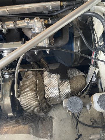
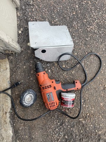
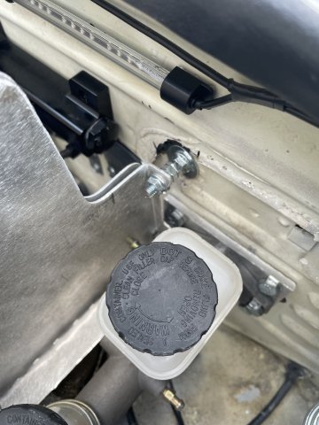
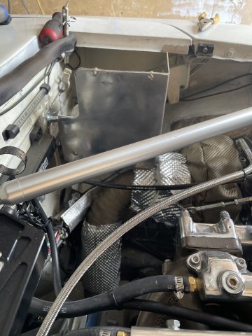
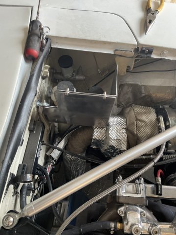
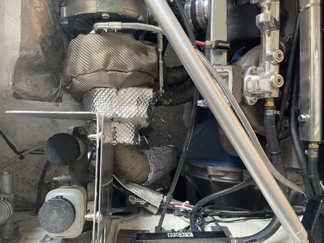
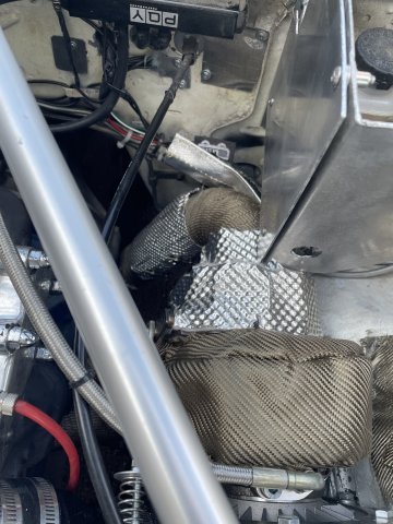
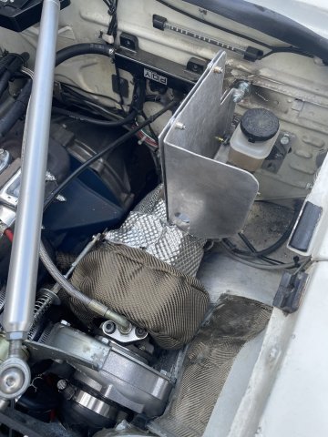
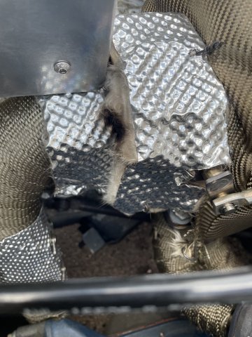
07-13-2025. HEAT. That was the issue I ended with the other day, so some insulation for the turbo I ordered on Amazon came in and I went ahead and installed some over the hot side (turbine) and end piece where the wastegate is. In doing that I removed the brake master cylinder heat shield and hit it with my buffing attachment in my electric drill with some Mothers mag wheel polish......not very good end product, but better than nothing. I also got rid of the screw holding it in place on the top bracket by drilling a hole and using a bolt with nuts and a washer to get it right. I took a bunch of pics, then took it for a ride. My work didn't solve the heat! Someone mentioned going from my stock 180 degree thermostat to a 160 degree one, so I found one on amazon for under 10 bucks and ordered it, and I am waiting for a new speedo cable as well, as my 53 year old original broke. When I got back from a drive I checked the temps of things under the hood, and the area I insulated was half as hot as the other day, but the engine still is running so hot. The tune is rich which makes engines run cooler and the hood is always open a hair now to cool it as well. the last pic is a spot where the insulation actually burned a dark spot! How would that happen? It's rated for 1100 degree continuous heat. Did they lie?? I just don't know what to think. Any ideas?
-
Hey friends, I’m pulling my hair out chasing a tuning issue and I’m hoping someone can please help me. Here’s the setup: 1972 240z with a rebello 3L with triple Weber 45’s, 280zx matchbox distributor with mechanical advance and vacuum disabled, MSD 6AL2 ignition and blaster 2 coil. 65F9 idle jets which is what Dave sent the motor with years ago and tuned on his Dyno, so I believe the idle jet selection to be correct for this motor. It’s been running rough at idle and lean popping through the carb throats which is typically a symptom of a lean idle, so I richened up the mixture screws, but that did not fix the popping through the carburetors. I’m also getting an extremely rich air fuel reading between 10 and 11 at idle. After using an infrared thermometer on my headers only cylinder number 4 is getting up the temperature, about 475° and the other cylinders are running between 100 and 350° at idle. When I pull the spark plug wires off of the spark plugs with the engine idling I get no change in idle quality when cylinders 3, 5 and 6, are disconnected, meaning they are either fully dead or only firing intermittently. I believe the rich AFR is at idle is due to these cylinders either not firing or firing intermittently dumping raw fuel into the exhaust. I have the base timing set at 18°, but if I advance the base timing, the RPMs will keep climbing and it will run better and better all the way up to about 40° base, however, this has no effect on the dead cylinders and doesn’t cause them to come back online. Heres what I’ve done so far to diagnose / rule out. Confirmed balancer mark is at zero when cylinder one is at tdc. Confirmed valve clearances on all 12 valves Ran both compression and leakdown tests. Compression is 210 across all six cylinders and there is no leakdown on any of the cylinders. Verified firing order / spark plug wires running to correct cylinders. Put a timing light on each of the six spark plug wires and confirmed none of them are skipping. Removed all idle jets and carriers, blew them out with air and visually confirmed they are free of any obstructions. checked for vacuum leaks at carb and manifold. Swapped carbs around and symptoms didnt follow the carb. Replaced Coil, Spark plugs, plug wires, Distributor cap and rotor. Added a ground strap to engine block. Confirmed good power and ground to MSD box. None of this has had any change and at this point, I’m totally scratching my head. Does anyone have any ideas?
-
I haven't used them personally, but a friend of mine has and had no issues with his interior parts. Fit was fine, plastic was a bit stiffer than the original. No complaints AFAIK.
-
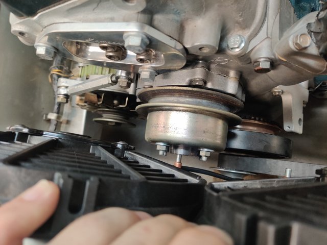
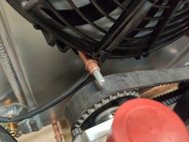
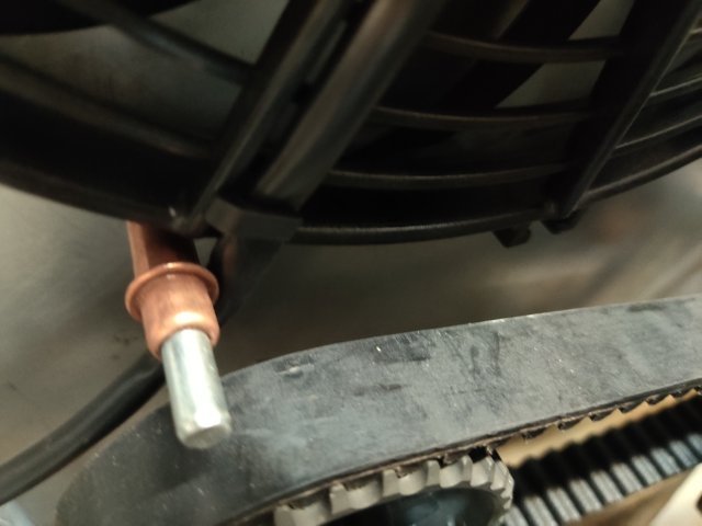
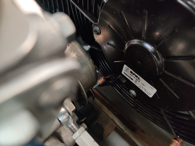
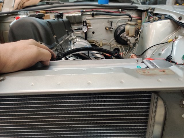
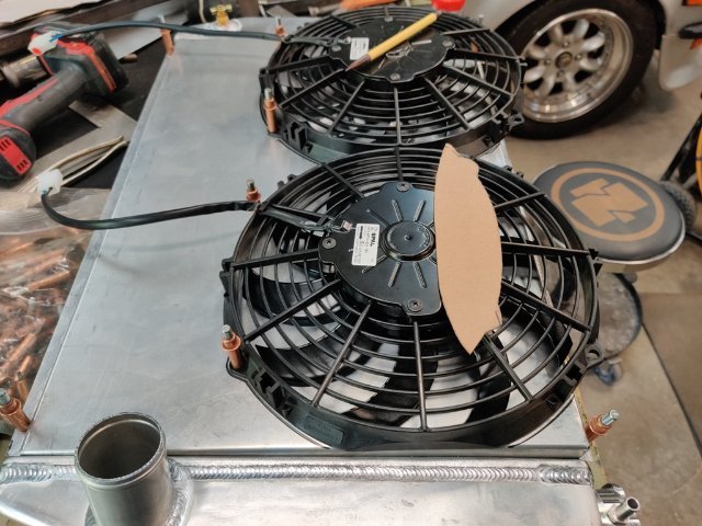
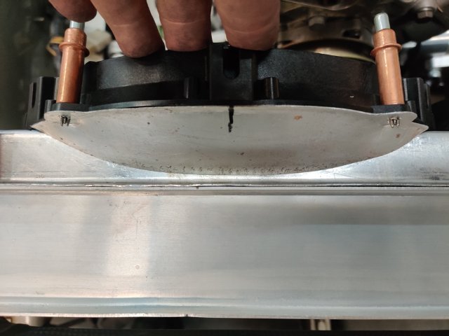
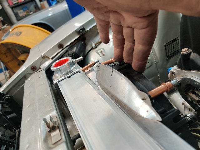
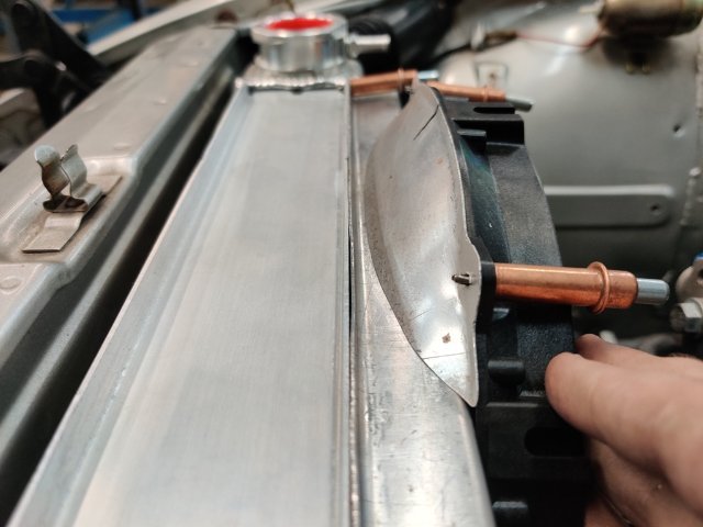
Progress today was slow because I ran into some further complications with adding a shroud along with the fans and radiator. Adding a shroud to my plan has made things more difficult. After much thought, I measured out and bent up a custom shroud. At the top, the shroud is spaced 1" from the fins. At the bottom, it is spaced only 1/4" from the fins. This was done to get a bit more clearance. So, it angles a bit from top to bottom. Additionally, I had to offset the fans so the top edge of them sits above the top edge of the shroud. This allowed me to get clearance at the oil pump belt. To cover the area where the fan extends above the shroud, I made a little aluminum extension. I plan to weld it to the shroud at the top. I will make another for the second fan and weld it in as well. At the lower part of the shroud, I will install some rubber flaps of some sort so that area will not just be a wall where air can't get through the radiator. I am going to replace the studs in the water pump (that hold on the pulley) with bolts instead. That will add about 3/16" more clearance to the fan. Additionally, I think I will need to put a strap on the inside of the shroud to strengthen it at the middle - this will be my attempt to keep it from getting pushed back (flexing) at high speed, and moving the fans closer to the rotating parts of the engine.


-
Who's Online 0 Members, 0 Anonymous, 563 Guests (See full list)
- There are no registered users currently online