cgsheen
-
Posts
676 -
Joined
-
Last visited
-
Days Won
9
Content Type
Profiles
Forums
Blogs
Events
Gallery
Downloads
Store
Everything posted by cgsheen
-
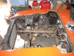
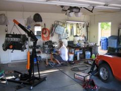
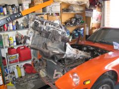
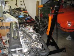
It all started with a 1983 L28ET...
-
-
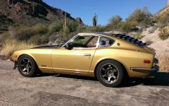
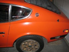
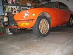
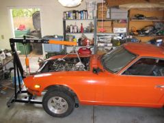
From the album: cgsheen's 1974 260Z turbo
This is how my 260Z ended up after we repainted her Fall 2012. This picture was taken in Early 2013 up in the hills (Supersition Mountains East of Phoenix, Arizona) -
The FSM should be enough although I'll have to admit it'll be MUCH easier if you see one whole, take it apart, and put it back together again. You'll start with all the door handle, lock, and latch mechanisms. Lots of rods and they all need to be put in place correctly - 2 ways to open the door latch, 2 ways to lock the door latch... Then you'll do the window regulator and a small 2-bolt horizontal channel that part of the regulator rides in. Then the window glass onto the 2 regulator arms, then the nearly vertical forward channel that the window slides up and down in. Then the window frame, adjust the bolts on the channels and the frame so it fits, follows the body line, and the window moves up and down and into the frame properly and snugly. Piece of cake. Then door card, handles, trim, door pull(s) and trim on the outside of the door (squeegee trim) - and I've probably forgotten something, but I'm old... But, you haven't said what year the 280 is - '77-'78 = wee bit different than the earlier 280's.
-
That's a pretty nice bottle BTW...
-
Ya, it's in the FSM. If you can't find it in the '75 look in the '76. It's a vacuum bottle and electric solenoid valves used for the heating and A/C system. Maybe I should say HVAC system.
-
Read the FSM. Fuel pressure is not a static (constant) value. The FPR should maintain a 36.3 PSI differential between fuel and manifold pressure. If your manifold pressure is -10 PSI (10 PSI Vacuum) at idle your fuel pressure should be around 26 PSI... In boost it should be greater than 36.3 PSI by the amount of boost pressure (ex. 6 pounds of boost should mean fuel pressure of 42 PSI). It should change continually as you drive because the manifold vacuum (and boost) will always be changing. If you have a "boost gauge", watch it as you use your right foot and you'll see what I mean. That's not likely to be your problem - or at least not entirely. +1 for running through the simple testing procedure in the FSM. "TPS seems to be working" ?? Very easy to test with an electrical meter - even a $4 Harbor Freight meter... It only has TWO positions that an L28ET ECCS cares about - open or closed. How to set it and check proper operation is in the FSM. So are the Ohm values for a properly working CHTS - unpluging it to see if the engine dies isn't the proper way to test. The other two temperature sensors in the t-stat housing have absolutely nothing to do with engine operation. One is the temp sender for the cockpit gauge - doesn't send any info to the ECU. The other is a thermotime switch - on the L28ET it is only used for the "hair dryer" - the aux. cooling fan - and also has nothing to do with the ECCS (on a stock 280ZXT, it cools the injectors / intake after engine shut down IF the water temp is too hot at shutdown. Vapor Lock. Never active when the engine is actually running.)
-
Eibach lowering springs uneven ride height?
cgsheen replied to 415DZ's topic in Brakes, Wheels, Suspension and Chassis
Youngsters... -
Black/Yellow is probably the start signal to the starter solenoid. If so, it'll go from the IGN switch to the dash harness to the connector block and Yellow out to the starter solenoid IIRC. Lots of trouble with the start signal in these early Z's (too much resistance, so the voltage drops along that stretch of wire until it's not quite enough to pull in the starter solenoid anymore. comon problem - you'll see multiple posts about the issue) Anyway, it wouldn't be a shock to see that modified around a crimp connection - that's where most of the trouble comes from... Looks like that's what the PO may have done - (soldered / jumpered around a crimp - may have saved you a starter problem...) Just make sure that exposed wiring is well insulated (covered, not protected from the heat or cold... ) You're getting the hang of this stuff - way to go.
-
L28ET swapped 72 240z idling funky & lack of power
cgsheen replied to superduner's topic in Trouble Shooting / General Engine
Stock L28ET ECCS? -
Ouch... Well, the first thought that popped into my head was: "why is he using a stock 260Z fuel pump on his turbo engine?" (I know you have an EFI fuel pump also - just use it, 86 the stock pump...) But that probably has nothing to do with your current issue. Sounds like a short (or shorts)... First. The harnesses are fairly well protected unless someone has damaged them or changed something in the stock routing that would cause them to "chafe" - like running unprotected through a bulkhead (hole in the metal, rubbing on the wire insulation until it gets all the way through to the copper) SO After you check all your fusable links (and figure out which each one "feeds"), and your fuse block for oxidized contacts, (They're made of brass - if they don't look like clean brass anymore - that's right, clean them... Fusable link spades too.) Start checking all your wiring changes. Next - might have nothing to do with you after all - the PO(s) may have left you with a surprise or two or three. You have some "hot" (+12V, not warm) wiring that's not connected or protected properly - disconnected but able to make contact - OR connected improperly in the first place. May be simple, may require an in-depth knowledge of the wiring diagram. I doubt there's a magic bullet for this one. Start posting pics of what's melted - along with some "context" (wire location, color, harness, components nearby). If you've got a temp gun, start finding the exact wire or wires that are heating up. Head to the FSM & wiring diagram (or individual circuit diagrams in the FSM). Could be resistance, could be short...
-
No clue buddy. I'm not that smart... Lot's of people here run early EFI manifolds on their L28ET. I don't. But you can search these Forums and ask around. I'm betting most of them aren't still running the stock ECCS though.
-
Well... The RPM comes from calculations the ECU makes (and/or values stored in it's base map) with the info from the temperature sensors and the CAS. The CAS is it's "tach" as well as engine position sensor, and it's monitoring intake air and engine temp through the other sensors. With a clean manifold, you'll probably run rich at idle with the stock ECU. It can't seem to throttle down the injectors enough on it's own at idle. That's why the Air Bypass and AAC - it seems to need additional air at idle to lean it out... Unfortunately you can't "tune that out" with the stock ECU.
-
The thermal switch on the L28ET is there solely for the "hair dryer" - the injector cooling fan. Has absolutely nothing to do with engine operation. If the water temp is above the "set point", the switch is made and the controller / timer for the injector cooling fan comes to life at engine shut down. Then it blows air over the injectors (and manifold) for 10 or 15 minutes, then shuts itself off. "Vapor Lock"... The thermal switch on early Z's has to do with timing and advance IIRC... But, he's right, it's in the FSM for the '74. No. That's ECU and the CHTS. The ECU will always raise the RPM on a cold engine. ~700RPM warm - ~900-1000 cold...
-
Sounds like an L6 - love that turbine noise. Way to go. I tucked my ECU up under the hood release cable. I also had to keep the plugs & sockets pointed out - my stock ECU had been dripped on for years apparently. The pins and plugs were really corroded. I had the worst time trying to get them clean and every-now-and-again I'd have to reach down and jiggle the wires to keep the engine running properly - fought with it for months after the swap. Glad I don't have to worry about that anymore...
-
260z L28et Build (first build newb)
cgsheen replied to Co0ke's topic in S30 Series - 240z, 260z, 280z
Wait. What? The Black/White originates at the IGN switch and energizes at IGN ON to power various components. Are you mistaking the White/Black that originates at the battery, through a fusable link, then to the Fuel pump relay as a "source" voltage for the pump? (Also "source" voltage to the IGN switch) Don't confuse those two... -
I was thinking along the same path as Tony - the Factory torque values are only going to be correct if you're doing the assembly exactly the way the FSM specifies. Change something, and how are you going to calculate what the "new" torque spec should be... That's why I just follow the FSM precisely in matters such as these - I'm not smart enough to figure out what any change would do to the specs.
-
cool.
-
L28ET Z31 ECU/MAF build thread
cgsheen replied to noelawinslow's topic in S30 Series - 240z, 260z, 280z
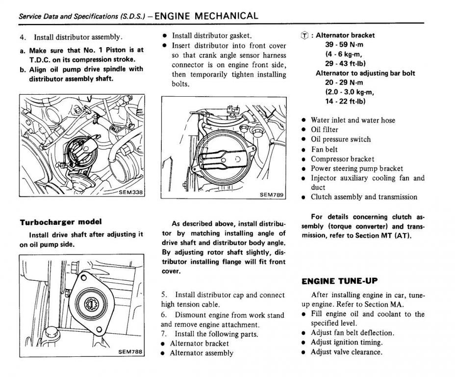
1982 280ZX FSM - Section EM (Engine Mechanical), page 21.
-
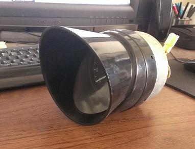
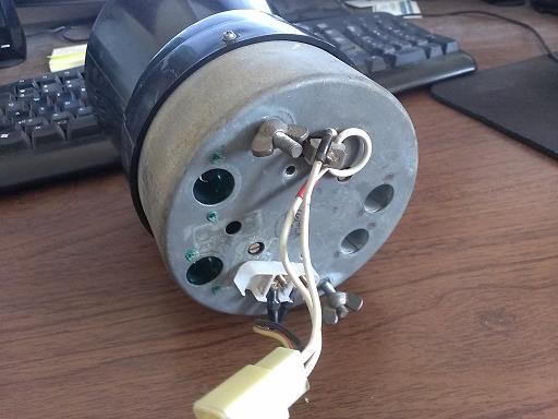
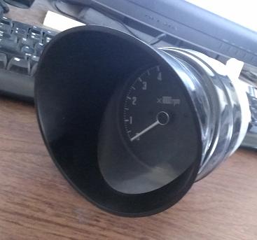
How? In an early, the tabs they mount to are welded to the dash frame. How do you get those out of the way to get the gauge out the back??
-
83 l28et swap harness into 73 240z wiring help!
cgsheen replied to AaronK's topic in Nissan L6 Forum
It may have been "plug-and-play" if the previous owner had explained how he tied all that wiring into his '73 harness... I hope it'll get easier, but from the pics you've posted so far, I'm afraid it'll be harder than it needs to be. You'll also probably have to back up a ways and take some new pics with more "context" - most of us aren't going to recognize some of those small snippets of wire ends (because that's NOT how we did the (re)wiring...). But seeing it with more context (more of the wiring harness in view) someone may see something and say: "OH... That's what he did with that wire..." I can tell you about your last picture: The "WTF is this box" is the Fusable Link Holder from a stock 280ZX. The Green and Brown wires going into the bottom are the main power sources for the ECCS system (ECU and engine harness). In it's stock form, this box will have power directly from the battery (and other switched sources) which will go through fusable links (same function as a Fuse) and then on to provide power to various components. You're obviously interested in the power to the ECCS. You need power from the battery to "feed" the 2 fusable links that feed the Green and Brown wires... That should be part of the engine harness that would go across the firewall from the master cylinders location and will also contain wiring for the CHTS (Cylinder Head Temperature Sensor) and the Knock Sensor, plus the EFI Relay (probably - well, maybe) and a white connector (most of this stuff ends up near the battery - it's location in the stock 280ZXT) It'll really help you to see an actual stock 280ZXT harness layout and make sure you have the Factory Service Manuals for both cars - the '73 and the '83 280ZXT (I find the '82 FSM easier to follow and it has the same info as the '83 FSM) The wiring to the Coil/Ignitor is in a seperate harness on the stock 280ZXT. It's not difficult to re-wire if you understand the circuit. I always found it helpful to have the original coil harness BUT it also contains a lot of other wires that you'll never need or use. The 280ZX had some other stuff up near the coil that required wiring... I just unwrap that harness, remove the unneeded wires, and wrap it back up. What you need in that harness is: Black/White (IGN ON power to the Ignitor and Coil - GND comes from the body (coil bracket bolted to fender well)), Blue (signal to Tach (which I just realized you can't use unless you swap out your early Tach for a '74-'78 Tach)), Yellow/White ("trigger" signal from ECU to Ignitor to tell the coil to fire - this wire ties back to the white plug that comes out of the ECCS harness near the ECU) Your next-to-the-last picture looks like the wire that goes to the O2 Sensor. If it is, it'll have a squarish body with a male spade on the harness end. Take it apart, show us the end. What's on the end of it right now is hard to recognize. -
Yup, it's all one piece. And, like you said, no screw for the early Speedo or Tach (that came later), 2 wing nuts on the backside, unhook the bulbs, wiring connector(s), and cable. They normally slide out with relative ease. With a full face dash cap you'll have a little trouble getting the closest part of the gauge bezel through the hole in the cap...
-
Oops, the '81 is wired differently at the EFI Relay. You need the wiring diagram from the 1981 280ZX FSM Turbo Supplement. Then you'll understand the wiring on that relay. On the '81 the injectors and primary power to the ECU aren't constantly powered. So, both the Brown and Green power wires from the fusable links go to the EFI Relay and then on to the harnesses. You have another set of wires to your relay, and you'll see no power to the injectors until IGN ON (with the '82-'83, that voltage is constant from the battery...) Don't worry about the CAS for now. Get all you other wiring straight and check it last. Normally that isn't a part you have to worry about going bad... It's connected to the ECCS harness, right (4-pin connector near the dist.)?
-
On the 280ZXT, the wiring to the coil / ignitor is seperate from the engine harness, just like your '77. It actually only has ONE wire that ties back to the ECU - the Yellow/White "signal" wire that's part of the ignitor plug. Your '77 already has the other two wires - they went to your original coil: A Black/White that comes from the IGN switch - it's +12V at IGN ON - powers both the ignitor and the coil (+). The other is a Blue, for the Tach signal. The turbo coil and ignitor get their GND from the frame & the coil/ignitor bracket being bolted to it (fender well). The only wire you're really missing is the ignitor signal from the ECU. Run a wire from the ignitor (HEI) to the correct pin on "plug 2" near the ECU and you're set - plus you've got the Tach hooked up (Blue Tach signal wire to same post (-) on the coil that the blue wire from the ignitor would connect to (in your case, HEI...) On "plug 2" there are multiple yellow's, there's even a YW on either side. The YW you're looking for is on the side with a Black, Yellow, and Yellow/White (maybe a 2nd Black) - the "wrong" side has a Green/Blue, Yellow, Yellow/White, (& maybe a Black) You can use some of your existing wiring OR you can recreate the 3 wires that are the stock ignitor harness: BW +12V from the IGN ON, Blue signal to the Tach resistor, YW ignitor signal to the ECU, GND to the frame.
-
Read the FSM. Fuel pressure is not a static value. The FPR is supposed to maintain a 36.3PSI differential between fuel pressure and manifold pressure. If you're pulling a 10 PSI vacuum at idle, the fuel pressure should read ~26.3 (example values - take your actual manifold vacuum pressure and subtract it from 36.3 - If you're in boost, add your boost pressure - I know I do - (sorry, I know the OP has no turbo, that's just for the guys that do...)). Explanation and chart in the Factory Service Manual. Just about every newbie thinks "it's the AFM" - most of the time it isn't (until someone screws with the AFM, THEN it's definately the AFM!). Unfortunately, there are very few AFM's left out there that haven't be molested in some way. In reality, most of them should never have been touched. If yours is unopened, untouched, you should leave it that way until you've checked, cleaned, checked, cleaned every other sensor, component, wire and connector on the EFI harness. How to test all of that is in the FSM...
-
vinegar therapy - rust removal inside coolant passages
cgsheen replied to PapaSmurf's topic in Cooling Systems
Housewives and plumbers have known the benefits of vinegar for eons when dealing with calcification. If you have the time, it works... Just me, but I can't stand the smell - and Evap-o-Rust works pretty well.