
cgsheen
-
Posts
678 -
Joined
-
Last visited
-
Days Won
9
Content Type
Profiles
Forums
Blogs
Events
Gallery
Downloads
Store
Everything posted by cgsheen
-
So not true. I'm actually amazed at the number of parts you can still get from Nissan for these old machines. Must be one lazy-a$$ parts counter dude... It helps if you have part numbers - which you can get online. And, there are a few Nissan dealerships that cater to Datsun enthusiasts so they have a bit more experience, but my local dealer has been very helpful finding parts for me.
-
This is the method I've had a great deal of success with: The theory is - if you can get the spindle pin to turn, you can get it to slide out. First off, it'll never hurt to remove the retainer pin (bolt), plug the bottom hole, and fill the top hole up with your favorite penetrating oil solution. Take the nuts off the ends and apply penetrating oil there too - for as long you can afford to let it sit, reapplying as needed... Now for the turning part: The threads on the spindle are exactly the same as a Datsun (Nissan) lug nut. I save the original nuts and use a couple of old lug nuts on one end of the spindle. With the lug nuts locked up, try to turn the spindle. I use an impact wrench. Otherwise a big ratchet (or ratchet with a cheater) - or, more likely, a breaker bar - use you own favorite turning device. If it'll turn, you can most likely drive it out. Once it turns, tap on the other end and see if it'll move. I always protect the ends with nuts over the threads - again old lug nuts work well here. Then I'm tapping on the face of the nut, not the end of the spindle. Or, when using a drift, a nut slightly off the end provides a "cup" for the drift and keeps the drift from going off one side and nicking the threads... If it won't move with tapping, go back to turning it. If need be, get some one else to turn the spindle while you tap the other end. A nut on the end will only let you go so far, then you'll need to remove it and start using a drift to push the pin all the way out. With this job, patience really is "the key to joy" - as a fortune cookie once told me... I've found in every spindle I've pulled that the retainer pin (bolt) has slightly deformed the spindle pin in some way. Usually very slightly, but the pin is pretty high tolerance and even a slight bulge will have a dramatic effect. Try it yourself: Once it's out and cleaned off a bit, put it back in and see where it "catches". Mine have always slid back in fairly easily until it gets to the notch in the pin that the retainer mates with. Finding the "bump" and filing it off has always made the pin easier to reinsert and position correctly for the retainer bolt to go back in. Leads me to believe that installing and torqueing the retainer bolt properly may be more important than you would think.
-
L28ET - cable throttle or bell-crank linkage (HELP)
cgsheen replied to 240zip's topic in Nissan L6 Forum
Ya, this depends on the throttle body and how it's set up. The stock L28ET throttle body is linkage - just like every other Z. Some people replace them with a newer and/or larger throttle body that uses cable. -
L28e died in my 280z... time to go with a l28et swap?
cgsheen replied to joshp's topic in Turbo / Supercharger
Hmmm... I'm not charging near enough for a turbo swap. I have an L28E in the shop right now from a '78 280Z. We just pulled it to swap in an L28ET. The owner has it listed for $350. Ran perfectly and it's 100% complete. I can put you in touch with him if you'd like. It's in Phoenix though... -
Ya, I couldn't find the BG (that's obviously there) on the circuit diagram either. If you look at the legend for the Ignition switch, you'll see that the BL only has power when the switch is in the Start position. Any other position and it is without voltage. I completely re-did my harness when I did my swap - almost 5 years ago - and I removed all the wiring that came across the radiator core support and into the vicinity of the coil. I have no reference left on my car to compare to the wiring on yours unfortunately... But on the stock 260, there were several components in that area of the engine bay that you won't have/need with a turbo engine that will have "left over" wiring.
-
The '74 circuit diagram shows the BL going straight from the IGN switch to the center lug on the ballast resistor with no other connection whatsoever. IIRC, the ballast resistor was used originally to help extend the life of points in the distributor. I come from "points era" automobiles, but I've long forgotten points and carbs - ran away from them actually! At startup, the ballast resistor is bypassed giving full voltage through the ignition circuit. When running, the power passes through the ballast resistor. Anyway, that's why the extra wiring. I don't know why they carried the ballast resistor into the electronic ignition era, but they completely got away from them in 1978, the ZX and beyond. (The '77 Z still had a ballast resistor, the '78 did not) The L28ET had none of that - which is why I've long said that you need to ignore (or delete) that portion of the ignition wiring system. It's "vestigial" wiring, left over from parts you don't need and shouldn't be using... If the BL is really attached to a B on the turn signal, that's wrong. Should have gone straight from the IGN switch to the ballast with no other connections.
-
I bought a new console from West Covina Nissan. Still available for the 260-280 from Nissan and it was "only" $140 at the time... MUCH more stout than the original console - the plastic is thicker in all of the critical areas. I waffled on the decision for any number of months - in the end, I'm stupidly happy I went this route. Having said that... The plastic used to make the console IS ABS and "plumbers" ABS cement is a very good glue to use for repairs. (Journeyman Plumber - can't tell you the amount af ABS plastic drain piping I've glued together in my career...) I've repaired a "cracked in half at the shift lever" console using the method(s) described above. Cracks that will have no stress can sometimes just be glued back together. Mostly you'll need the "piece of ABS plastic glued to the underside method" to stabilize and reinforce the damaged area. I used strips / pieces of ABS glued to the backside for strength and clamped them up while the glue set. With yours, recreating the missing mounting holes will be the toughest part - and you have a good amount of material missing. That'll take some patience. Best of Luck which ever way you decide to go.
-
Otherwise it's just a 4-spade (female) plug common to Datsuns/Nissans around that era. To build my F31 ECU harness, I just found a clean plug in my "tons of old Z wiring" bucket and attached it to the shielded 4-wire cable I bought to run the CAS signals, power, and ground. It doesn't have a rubber boot, but - A. I never drive the Z in the rain B. It never rains here anyway. I could have used a stock plug, but figured "why hack up a nice stock harness component when I can just use one of these plugs I have lying around". It's been almost 2 years of daily driving with the "new" ECU harness...
-
Goldie

-
The VCM can certainly fail. And there's a big rubber diaphragm in there to harden, crack, leak... The FSM will show you all the potential vacuum problem spots if you look carefully. You can delete the VCM but take care to plug or reroute all the vacuum lines involved. It has a couple of connections to the intake chain IIRC, and controls both the A.A.C and the EGR with separate vacuum lines to each. Normally if the engine mechanical timing is spot on, having the distributor set in the middle of it's adjustment range is close enough. But you can always loosen that up and see what moving the distributor through it's adjustment range does to engine operation. I found an L28ET that was off a tooth on the drive spindle by turning the dist. and seeing where it would run... The CAS is normally a "go / no go" type of thing. Won't hurt to test it for signal and while you're there check the chopper wheel and make sure none of the slits are buggered up.
-
Just looked at the spare harness - Yellow is temp sender, White is thermotime switch. The 4 shielded wires are CAS. You're correct, Black/White is IGN ON +12V, Black is GND, the greens are signal from the optical sensor - one is the one degree signal, the other is the 60 degree signal. Don't know which is which yet - I'll have to cut the harness wrap to find out...
-
My L28ET has always run about 10-12psi of vacuum at idle (both stock and with VG30E engine management). 5 doesn't even sound close to right. Find out why your vacuum is off. Vacuum leaks make these engines run like crap and there are a few unusual vacuum components many people wouldn't see as potential problems - like the VCM as an example. There is no mechanical or vacuum advance on these engines. That's all handled by the ECCS. Set your timing at 20 degrees and the ECU handles the rest. What coil/ignitor are you using with the Z31 setup? I have to say again that most of the problems with these engines come from wiring / electrical issues. Check and clean all the connections and connectors - then do it again. Verify that you've made the proper wiring changes for the ECU and MAF. You may need to start at the beginning - verify engine timing (chain / gears, oil pump / distributor shaft / rotor). Then start with the engine electronics - which all starts at the CAS (yes, you can test it - if the procedure isn't in the Z31 FSM, download the 1990-91 Infiniti M30 FSM - same optical sensor & wiring the L28ET uses...). Test every ECCS component and check and clean each of their connectors (both sides). Remember that fuel pressure is a 36.3 PSI differential between the fuel rail and manifold pressure. 36.3 minus the vacuum PSI unboosted and 36.3 plus the boost PSI when running in boost...
-
What keeps the window from sliding backward (or forward) and out of the tracks is the verticle guide in the forward part of the door. There's nothing at the rear-end of the window or it's frame that will help you in that regard IIRC. There's also a short horizontal guide (5 or 6 inches long, 2 studs attached, just forward of mid-door) that needs to be in place. Take a pic of you entire door (focused if possible ) and let's see if you have all the parts you need... The FSM should have fairly good diagrams of how all that goes together.
-
Toying with the idea of starting a 240z restoration but...
cgsheen replied to NickA's topic in S30 Series - 240z, 260z, 280z
Exactly right. -
Or maybe the yellow goes to the water temp sender on the thermostat housing. Do you have a Factory Service Manual and a electrical circuit diagram? Download the FSM at xenons30.com for from nicoclub.com/fsm. Get the '72 FSM if you can't find the "1970-1971 Datsun 240-Z Sports" FSM...
-
You can say THAT two times!
-
Ya, It's the EFI Relay - the Fuel Pump Relay is a completely different part. Ordinarily you'd use your existing (stock) 280Z relay and re-wire it to be triggered by the new ECU - or - wire in a new simple relay to pass power on to the fuel pump. It's important that the ECU controls the fuel pump for safety considerations. Sorry I didn't read the whole thread - did someone tell you the stock L28ET coil has an Ignitor strapped to it? The stock 280ZX Coil/Ignitor have a harness seperate from the ECCS (engine/ECU) harness. If you don't have it, you can use the Black/White (+12V @ IGN ON) from your stock coil (+), AND the stock Blue (to get Tach signal), BUT you need the signal from the ECU to the Ignitor and the amplified output from the Ignitor to fire the coil (-). If you don't have a stock Coil/Ignitor you can use an appropriate coil and a GM HEI Ignition Module (threads beyond count about using a GM HEI...)
-
Amperage is kind of "volume of current". It's sort of like how much water can flow through a given size pipe. Having a relay that will handle more amperage than the stock relay in and of itself can do no harm (except it may be "masking" other problems that might be present in your electrical system). A relay is just a switch (or set of contacts) that's operated by an electromagnet. It's amp rating is how much electrical current the switch mechanism inside can safely pass through. Too much current creates resistance which creates heat which oxidizes contacts which creates even more resistance which creates even more heat which - ya, leads to even more problems... Having said that, I have to agree with Domz. I just don't see why your fuel pump would be drawing that many amps (although I've never put an amp meter on a fuel pump). Still, pumps come with specs. Electric motors always have a specified amp draw. You should be able to find out real quick how many amps your fuel pump should draw. My thinking is: why would you ever need a relay rated much higher than the fuse that protects the circuit.
-
Truer words have rarely been spoken...
-
Man, I wish you lived closer Heroe...
-
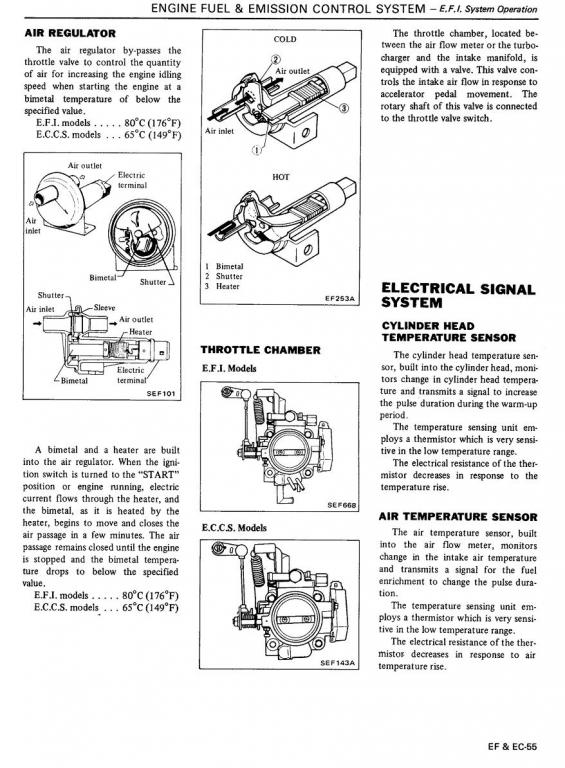
Too high idle, found this thing; what is it? what does it do?
cgsheen replied to spiff's topic in Nissan L6 Forum
From the US FSM
-
How do I interpret the amp meter
cgsheen replied to RebekahsZ's topic in S30 Series - 240z, 260z, 280z
Did you test the voltage you're getting at the spade that connects to the starter solenoid? Pull it off and have someone turn the ignition switch to start while you're checking the voltage. If it's not close to battery voltage, and changing switches hasn't helped your problem, you may need to run a new "start signal wire" from the ignition switch (Black/Yellow) to the starter solenoid... -
My Son and I really like the Exedy clutch kits in our turbo cars. His has been hammered on for the last 6.5 years, mine (not hammered on) for 4.5 years - both daily drivers.
-
1974 260z- Turbo swap, complete overhaul
cgsheen replied to xxjoeyxxeb's topic in S30 Series - 240z, 260z, 280z
Mine too... -
Well, don't follow the above wiring scheme if you're using the stock 280ZXT coil/ignitor - it's wrong for that... Using a Z31 coil/ignitor (yes, you can) - it's probably wired like my M30 coil/ignitor, but you'll need the Z31 circuit diagram. On the stock 280ZXT coil/ignitor: - B/W comes from ignition switch - +12V at IGN ON - to top of "T" connector on ignitor. - B/W out of ignitor goes to "+" terminal on coil. - Y/W comes from ECU pin 5 (through connector "3" (plug 3) near ECU on the stock 280ZXT harness) to leg of "T" connector on ignitor. (Y/W from ECU pin 5 is "signal to fire" from ECU) - L (blue) from ignitor goes to "-" terminal on coil AND back to provide Tach signal (through resistor to Tach) (L (blue) from ignitor is amplified "signal to fire" from the ignitor to the coil) - Ignitor is grounded through the coil mounting bracket to the body. - If there's a Black wire coming out of the ignition harness (wiring harness to coil/ignitor) with a female bullet connector, it's probably for the condenser, IF IT IS it's HOT - it'll be coming from the B/W inside the harness. There has to be a condenser between it and ground or N/C. (Easy to test if it's a GND or for the condenser connection: If it reads +12V (battery voltage) at IGN ON, it's for the condenser.) Stock, it goes to a GND spade on the distributor (through the condenser) to help eliminate electrical noise that could interfere with the ECCS.