cgsheen
-
Posts
676 -
Joined
-
Last visited
-
Days Won
9
Content Type
Profiles
Forums
Blogs
Events
Gallery
Downloads
Store
Everything posted by cgsheen
-
Ignition relay wiring L28ET Swap in '77
cgsheen replied to Ben's Z's topic in Ignition and Electrical
You should put up pics then we'd be sure, but I'm pretty sure you found the Tach resistor. I think you got the wrong wire though. Did you look at the FSM for your '77? Pretty sure the Blue comes from the coil and the Blue/white goes to the Tach. (yup - just looked at the FSM (Body Electrical, page 31)... Connect your new blue wire to the blue wire on the resistor and reconnect the blue/white, it goes to the tach.) So, wiring goes like this: Blue (from "-" side of coil) --> blue on resistor --> resistor --> blue/white out of resistor --> tach. -
Ignition relay wiring L28ET Swap in '77
cgsheen replied to Ben's Z's topic in Ignition and Electrical
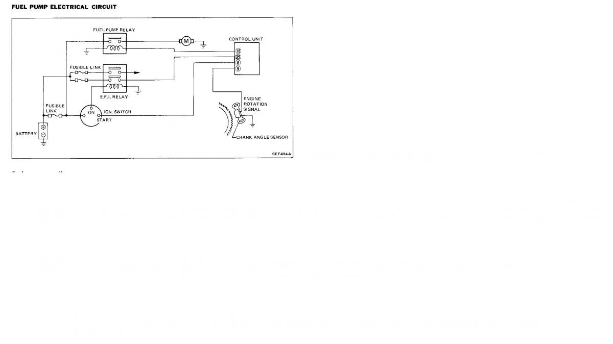
This diagram in the FSM shows the EFI and Fuel Pump Relay in simple terms. Doesn't need to be more complicated than that. Pin 16 on the ECU is "the trigger" for the relay. It's the Lr (Blue/Red) wire from pin 16 to the 6-pin "connector 3" on the stock ZXT harness. Do this however suits your wiring setup: Blue/Red from pin 16 connects to the fuel pump relay coil. The other side of the relay coil goes to GND. IIRC "connector 3" in the ZXT ends up near the battery (or firewall penetrations on the passenger side) - and that's where I put mine. That's near where my fuel pump relay is, so it's a short hop from connector 3 to the relay. Doesn't matter, you just need to run a wire between pin 16 on the ECU to the coil on the fuel pump relay...
-
Ignition relay wiring L28ET Swap in '77
cgsheen replied to Ben's Z's topic in Ignition and Electrical
Nope. And, just so you know, I've done multiple swaps (other cars, not just mine) - used both types of harnesses. Currently I'm using neither - my "new" engine management is from a 1990 Infiniti M30... -
Ignition relay wiring L28ET Swap in '77
cgsheen replied to Ben's Z's topic in Ignition and Electrical
4. Ya... Sort of... In the ZX there's a positive battery connection to that black box (the fusable link holder). The Fusable Links connect to that, the Br & G wires connect to the Fusable Links. Personally, I used the black box - left the sockets for the two ECCS fusable links and the Br & G wires in place (mounted the black box to my firewall) and just spliced the +12V "feed" wire into the positive side wiring on the battery. (Or, get a circular electrical connector of an appropriate size and connect it to the starter - same place the positive battery connection is attached) But, the point is: Positive side of battery --> fusable link (or fuse) --> Br wire |__ --> fusable link (or fuse) --> G wire 3. Get under the passenger side of the dash. Find the square (rectangular really) Tach Resistor - It'll be just outside the taped up dash harness (so a person can change it). It doesn't look like a resistor at all - it looks like a small plastic box with 2 wires coming out one side. The signal from the Ignitor needs to go through the resistor before it goes to the Tach. Find which of the wires come from the engine bay (there will be 2 wires attached to the resistor). Cut the wire that comes from the engine bay and replace it with the new blue wire you just pulled through the firewall. Voila! Tach signal... 2. My advice: Run the power feed from the fuel pump relay straight to the fuel pump. Let the ECU and only the ECU control the fuel pump operation. On my Z, that just meant hooking the feed from the relay to the existing pump wiring right there in the passenger footwell. I'd advise getting rid of any other modifications to the pump wiring. 1. I don't know that I quite understand what you did with what would normally be the condenser and it's wiring between the coil and distributor... But: - The engine will run without the condenser. - If you don't have a condenser, there's no reason to connect the wiring to the distributor - The condenser is to help eliminate electrical noise - helping the ECU "hear" what the sensors are telling it without a lot noise getting in the way. Get one when you can and install it & wire it up to the dist. - until then, don't worry about not having one and don't make that wiring connection! (IIRC one side of the condenser is attached to the +12v IGN signal at the coil and the other goes to GND on the distributor body. You don't want a wire between those two points without the condenser in between!) On the Coil/Ignitor harness. It doesn't matter where you pick up the +12V IGN ON (BW wire) - spliced in near the IGN switch - OR whether you use the one your old coil used. It just needs battery voltage (no ballast resistor) at IGN ON. (I spliced it in near the IGN switch because I had the ZX coil/ignitor harness all bundled up so I took all that wiring through the firewall and made connections under the driver dash. It also made it simple to trace and I knew exactly where my coil power was coming from...) -
I think the feedback is very good. I was - surprised - the assist doesn't "get in the way", feels very natural... IMO it retains the feel while lowering the effort. And of course you can "dial in or out" the amount of assist you want or turn it off completely. It feels nice at speed, doesn't over-react to slight input. I suppose that's what surprised me, the fact that it "knows" when you want/need more assist and when to stay out of your way. That's the magic of microprocessors I guess...
-
+1 I've driven Hitman's Z, the electric assist is pretty darn cool. Makes it stupidly easy to steer - especially at low speeds - even with those giant-wide tires of his... Fits nice under the dash - don't know it's there until you turn the steering wheel!
-
water temp sensor to gauge wire
cgsheen replied to AZGhost623's topic in Trouble Shooting / General Engine
Cool. -
water temp sensor to gauge wire
cgsheen replied to AZGhost623's topic in Trouble Shooting / General Engine
1976 280Z FSM - Body Electrical, page 34 (BE-34) shows Yellow/White from the gauge (dash harness) to C5 (Green connector) on the junction block. The junction block is in the passenger footwell so it must exit the firewall with the body harness and run up the passenger side of the engine bay, across the radiator core support and back down the drivers side with the coil wiring and etc. It's bundled in that vicinity with other wires attached to a 4-pin plug, from the 4-pin plug it goes yellow to the Temp Sender... That's how it was stock anyway. FSM dude... -
My Son has had a T-5 in his '76 280Z since we turbo swapped it 6 years ago. He really likes that transmission and he's had no problems whatsoever. He put a short-shifter on it almost immediately. I like the way it shifts - quickly, nice positive feel... I don't like the lower gear ratios, maybe it's just 1st that really bothers me. The turbo engines have a fair amount of torque and IMO can handle a taller gear in 1st... I have the Nissan "close ratio" 5-speed in mine ('82-'83 280ZX 5-speed) and I prefer the gear spacing in that transmission, but I wish it shifted like my Son's T-5...
-
Yup. Just like that...
-
The stock ignition harness on the ZX is seperate, runs from the coil / ignitor down the driver fender and comes out under the dash. IIRC it's also bundled with some other wiring for accessories that are just farther forward than the coil. It can be pared down to a few wires, so it's relatively easy to make your own. You should already have a Tach signal wire in the vicinity of the coil - use that, hook it up to the coil as shown in the 280ZXT wiring diagram (goes to the same post on the coil that the signal OUT from the ignitor connects to - stock, they would both be blue wires). You need the signal wire from the ECU to the ignitor. You need +12V from the IGN switch @ IGN ON (stock = Black/White wire from IGN switch) This powers both the Ignitor and the Coil. The Ignitor needs a GND (which I believe normally comes from the coil bracket it's mounted to, which is mounted to the body - but that's easily available from the GND connections to the engine in the vicinity of the coil. All the GNDs bolt to the intake manifold right beside the strut tower. In the stock harness there's also a connection for a condenser between the coil and a spade on the distributor. Not entirely sure, but it sounds like the "black box with the white wires" you're referring to is the fusable link box from the ZX. I used the one from my donor (I have a 260Z though - no EFI stuff in there already...) It did make the wiring to power the ECCS system easy. I mounted mine on the firewall and connected the big white wire that feeds power to the fusable links for the ECCS to the battery. (eliminated or abandoned the other fusable links in the box because I only needed the ones for the ECCS) You should already have EFI fusable links you could use though, right? Still, might be simple to use the ZX box... Be sure to use the ZX fuel pump relay and run the output straight to your fuel pump.
-
The Ignitor is an amplifier. It takes the signal from the ECU and amplifies it to state that will fire the coil. Simple as that. And yes, the GM HEI works as a substitute, it's easy to find, and cheap to purchase. There are several threads on how to hook them up - they have 4 spades: power, ground, signal from ECU, signal out to coil...
-
83 Stock Turbo will not fire
cgsheen replied to daddydonuts's topic in Trouble Shooting / General Engine
The wiring between the fuel pump relay and the fuel pump. Run a new "hot" wire from the relay to the fuel pump and see how that works. You've already checked to see if the pump has a proper GND, haven't you? Then you can decide whether to leave it, or tear into the body harness and find the source of the problem. Do you have trouble with any other electrical items in the back of the car? (wondering if you have some shorted, melted, wires in the bundle...) Oh, I've always meant to ask if you have a stock 1983 280ZX Turbo or if we're dealing with an engine swap... -
Not on the L28ET. And not on a '77 Tach. Wiring the Tach is a simple process - the Tach feed is the post on the Coil that has the blue wire attached (should be 2 blue wires - one from the Ignitor - the 2nd one is the Tach signal. It just needs to be connected to your existing Tach signal wire BEFORE the in-line resistor. But, that wire is simply a signal to the Tach - has nothing to do with the ECU or engine electronics. The ECU has it's own "Tach" - the C.A.S. tells it all it needs to know about engine rotation.
-
The injector is a coil (electromagnet). It does have a constant +12v to one side, the other side is grounded by the ECU when it pulses the injector. Because it's a coil, when the connector is plugged in, the voltage will pass through and show on the other side when you test it with a meter. That's normal. Test that it's being pulsed by the ECU with a "noid light" (or get a 12v bulb in a socket with the wires attached, remove the injector connector, and push the wires into the connector). The light should flash as the other injectors click. While the connector is off, "Ohm out" the injector - they're low impedance so I think they should read about 2.3 Ohms across the two spades. (the FSM will have the exact value). If the injector checks out in that regard, you know it's coil is intact. Then it could just be stuck. I've had to manually work some of these old injectors to get them opening again. Being stuck closed is probably more likely than it being clogged, but you'd only know that if you pulled the fuel rail and watched it spray or pulled the injector out and had it flow tested. If you did that you'd want to do them all... It may take a bit to get the cobwebs out... Get it running, get some injector cleaner in it (or Marvel Mystery Oil - or both), and let it burn a few tanks af gas. Oh, you've pulled apart all of the electrical connectors on the engine harness & ECU, checked them for corrosion, and cleaned and de-oxidized ALL of them , haven't you?
-
My Son's L28ET has a stock turbo that's very audible. You can hear that thing spin up (and down, and back up again)... I expected mine to be much the same, but it's not. You can feel when it starts to spool up, but you can't really hear any "turbine noise" from mine. I've always wondered if it's the difference in our exhausts or something.
-
36.3 PSI at zero vacuum. I'd suggest you jump the fuel pump to get it working without the engine spinning and set your fuel pressure. But, pulling the vacuum line off the FPR is going to get it to zero vacuum as well. Engine might run kinda funky...
-
It's a condensor to help eliminate electrical noise (like the one over on the alternator). Has nothing to do with spark and nothing to do with the Ignitor. Just leave it bolted up to GND and look elsewhere. Have you checked your CAS signal? (just looked at the pics you posted @ zdriver... sorry man... that's gotta be a little confusing. the last post made over there is WRONG about the ECU light. Ignore that comment. The exact function of that light is well documented in the FSM (wish I could post over there and tell him to stop posting incorrect info - might have to register...) I probably have some suggestions on the wiring. (I'd re-do most of it if it were mine.) You need to have a pretty good understanding of the wiring in BOTH cars (your early Z, and the 280ZX Turbo that the engine came out of (at least the ECCS harness and how it connects to the 280ZXT main harness) - be sure you have both FSM's. Did you really get it to fire with starting fluid?
-
83 Stock Turbo will not fire
cgsheen replied to daddydonuts's topic in Trouble Shooting / General Engine
Ouch... Your topic title says "83 Stock Turbo". The pages you show are for the EFI 280ZX. You should be in the ECCS Section of the FSM if you have a turbo model (280ZX Turbo)! And that's the pinout I have been refering to - the ECCS ECU. The N/A car is also fuel injected but it has a completely different computer (ECU) and engine management system than the Turbo! "EFI" is for the normally asperated engine. "ECCS" is for the turbocharged engine. If your ECU connector looks like the pictures you posted, the harness is from the EFI (N/A) version and can't be used to run the stock turbo engine. The ECCS (turbo) ECU has 3 seperate plugs (black plastic) that go into the side of the ECU, not a single long plug like the EFI ECU... -
The fuel pump should be wired similar to the EFI relay except it's a signal (voltage) from the ECU that sets the coil and turns the switch ON. So, fuel pump coil should be GND on one side, connected to ECU pin 16 on the other side of the coil. Pin 16 will control the relay (which turns the fuel pump on and off...). You'll find that this is one of the ECU wires that goes to either the #2 or #3 connector which connects to the main harness in the 280ZX. That's normally one of the wires you have to connect into your own harness to get it to your fuel pump relay.
-
83 Stock Turbo will not fire
cgsheen replied to daddydonuts's topic in Trouble Shooting / General Engine
I don't think you've provided enough information for anyone here to actually determine: "to me, if I'm correct, the ECU is the problem." "27 then, It failed that test" - Meaning? - Does it read battery voltage on ECU pin 27 when you turn the ignition switch to ON? - Does it read battery voltage on ECU pin 35 when you turn the ignition switch to ON? - Does ECU pin 114 have constant battery voltage? - Every GND connection (ECU pins 107,109, 112, 113, 36, 28) is properly connected to only GND? - Does the green LED inside the ECU case come on when you turn the ignition switch to ON? ( there is a hole on one side of the case from which the LED should be visable) "plus my fuel pump pin test..." - Well, if all the above is TRUE, and all the voltage and GND tests are normal, AND you get no green LED light from the ECU, then go no further. You won't get the fuel pump signal for ~5 seconds at IGN ON. The ECU controls the fuel pump so if the ECU doesn't "come to life" neither will the fuel pump. -
83 Stock Turbo will not fire
cgsheen replied to daddydonuts's topic in Trouble Shooting / General Engine
Which? Pin 26 on the ECU goes to the AFM and the CHTS (cylinder head temp sensor). Pin 27 is the "turn me on" voltage from the EFI relay. It (the ECU) gets voltage from the EFI relay to pin 27 and 35 at IGN ON? It has a constant voltage to pin 114 (and the injectors)? The GND's are correct (multitude of pins... refer to the FSM)? The green light comes on or not? -
Dang! Just wrote a longish reply and lost it! Gist: EFI relay should have GND on one side of the coil, no voltage on the other with IGN OFF, battery voltage with IGN ON (B/W from ignition switch). The Brown wire is source voltage for the internal switch - constant battery voltage at it's connection to the relay. The other side of the switch is output to the ECU - no voltage with IGN OFF, battery voltage at IGN ON (B/W wire to ECU). If all that is true - bad relay.
-
You've got the 1982 280ZX FSM and the turbo wiring diagram? (I have the 1983 FSM as well but I find myself using the 1982 instead). 2 main power supply wires to the ECCS system: 1 Green, 1 Brown - in the ZXT they go through fusable links off the battery. Green is constant power (+12V to the injectors and is the only Green wire on the 3-row (17 pin) ECU connector), Brown goes through the EFI relay and is switched ON at IGN ON. The Brown feed comes out of the stock EFI relay as Black/White and also powers other ECCS components. It connects to the ECU on 2 pins in the middle connector (16 pin) directly across from each other - I think the only Black/White on that connector. It also powers the VCM solenoids and the Crank Angle Sensor.