
cgsheen
-
Posts
678 -
Joined
-
Last visited
-
Days Won
9
Content Type
Profiles
Forums
Blogs
Events
Gallery
Downloads
Store
Everything posted by cgsheen
-
Read the FSM. Fuel pressure is not a static value. The FPR is supposed to maintain a 36.3PSI differential between fuel pressure and manifold pressure. If you're pulling a 10 PSI vacuum at idle, the fuel pressure should read ~26.3 (example values - take your actual manifold vacuum pressure and subtract it from 36.3 - If you're in boost, add your boost pressure - I know I do - (sorry, I know the OP has no turbo, that's just for the guys that do...)). Explanation and chart in the Factory Service Manual. Just about every newbie thinks "it's the AFM" - most of the time it isn't (until someone screws with the AFM, THEN it's definately the AFM!). Unfortunately, there are very few AFM's left out there that haven't be molested in some way. In reality, most of them should never have been touched. If yours is unopened, untouched, you should leave it that way until you've checked, cleaned, checked, cleaned every other sensor, component, wire and connector on the EFI harness. How to test all of that is in the FSM...
-
vinegar therapy - rust removal inside coolant passages
cgsheen replied to PapaSmurf's topic in Cooling Systems
Housewives and plumbers have known the benefits of vinegar for eons when dealing with calcification. If you have the time, it works... Just me, but I can't stand the smell - and Evap-o-Rust works pretty well. -
No ECCS Green light nor fuel pump priming
cgsheen replied to Ben's Z's topic in Ignition and Electrical
You don't need one. Not having one will NOT keep you from starting or running the engine once you get everything else wired correctly. From the pictures above (hard to tell, BUT) I don't think you have everything else wired correctly... -
Clicking noise from under the dash
cgsheen replied to jakez's topic in Trouble Shooting / General Engine
Well... I have a fuel pump relay that clicks... Not the same setup at all, but I'm using an old, original relay that I should have changed out a long time ago. I've checked the wiring and ground, but I guess it's just old and tired and doesn't hold in 100% of the time. Fairly randomly the coil let's go, then engages again - I can hear it click when it does. -
NO! If you don't need them, leave them alone and unplugged. The ECU does not need to be attached to the body in order to work. I have one now laying on the carpet under the steering wheel - engine starts and runs fine... If the stock harness was intact, there should have been 2 or 3 ground wires on the turbo side of the engine that bolt to the intake manifold. (they come out of the harness where it crosses over to the engine - by that clamp on the intake manifold) If it was intact, that should be all you need there. But, again, make sure the connectors and wiring are good. The FSM shows the GND pins on the ECU and how to test them. Then just make sure the grounds on the battery side are good (battery to body, to starter mounting bolt, alternator GND's...) OK, injectors sat for 4 years - do you know that they open and squirt gasoline? Are all of them "clicking"? Will the car start and run with starter fluid squirted in the AFM?
-
The ECU doesn't monitor Oil Pressure. The CHTS is important for the engine to run properly. It's a temp sensor with the same resistance curve as all the Nissan temp sensors of that era. Easy to test with an Ohm meter - the chart (and test procedure) is in the FSM. If the engine's mechanical timing is all set properly, the dist usually works centered. The ECU controls ignition timing so as long as the distributor is close, the ECU can take it from there... Have you double-checked the AFM (is it unmolested, or has someone changed the spring setting)? How long did the injectors sit unfired? Are all of them opening?
-
You have that wired correctly. The "top" of the T is +12v at IGN ON (BW wire from ignition switch) and the "leg" of the T is pin 5 of the ECU. ( there are two YW wires on connector 2 ( plug 2 ) on opposite sides of the plug - just be sure you're on the correct wire when attaching to connector 2)
-
The stock L28ET ECU sends the signal to fire the coil out pin 5. On the stock ZXT harness, it goes from Pin 5 on the ECU to Connector (plug) #2 (8-pin connector near the ECU - Y/W on the side with: N/C, YW, Y, GL) and from that connector straight to the ignitor. The other side of the stock connector at the ignitor is +12V (BW) from the ignition switch @ IGN ON which powers the ignitor and the coil (BW from ignitor to coil+).
-
OK, but I don't use MS and don't ever plan to... But, I wouldn't mind using the COP engine management from a J30, Z32, or the like (something I could NISTune) on my L28ET. I need to talk to Bernardd...
-
I always forget about NicoClub - http://www.nicoclub.com/FSM/ - as a resource for Factory Service Manuals (sorry Greg). Lots of FSM's there too. Turbine, Forced Induction, Compressed Air...
-
Sort of. Smaller optical disc, and the 4 pins come out the side (exit in the same plane), not the bottom (not at a 90 degree angle to the circuit board as the L28ET module does). There has to be a better way to use one of these on an L28ET other than milling a spacer and modifying the end of the spindle so you can bolt a cam angle sensor (from a J30, or an RB or a VQ) in it's entirety onto the L28. (or is there - and I just missed it...)
-
Go to xenons30.com / reference section and download the Factory Service Manual for both of your cars: The '77 280Z and the 280ZX. I'd suggest the '82 FSM for the engine and associated parts - I think it's a little easier to follow than the '83 FSM. Get all - can't hurt. First, if you're using the stock ECCS system, don't "leave anything off" unless you completely understand how it's going to affect how your engine runs. You can't go in and tune that ECU to compensate. My opinion, but if experience holds, you're probably going to be chasing a few gremlins and you may not need the gremlins thrown in by deleting components confusing things. Get it running properly stock first, then get the info on what and when to change. 1. You need a coil and ignitor but not necessarily the stock items if they're unavailable to you. Search the Forums for "GM HEI module" - it's a ~$30 part used on Chevettes (and Corvettes) that can be wired in place of the stock ignitor. Simple, cheap, works well. 2. That's the Vacuum Control Module (VCM) - it controls both the A.A.C Valve and the EGR Valve - info in the Factory Service Manual. 3. Fusable Link box from the 280ZX. You have a couple of those near the battery of your Z - covered with white lids - 2 fusable links in each one. Your choice to wire power to the ECCS system: Use the 280ZX fusable links for power to the ECCS or figure out how to wire the G and Br ECCS power wires into your fusable link... You should understand both the wiring diagram for your Z AND the 280ZX ECCS and it's interface with the body of the ZX... Factory Service Manual.
-
no power to black and white wire on ignition switch
cgsheen replied to Clashez's topic in Ignition and Electrical
Well, you may be thinking of it the wrong way round... The Black/White wire is energized by the ignition switch at IGN ON and generally goes on to power EFI relay, coil, ignitor on turbo cars, and various and sundry other things. The source voltage comes from a White/(usually) Black (sometimes White/Red) from the battery and/or alternator output - to the switch... If you have voltage on the source wire, but no voltage on the B/W when you turn the IGN switch to the ON position, signs would point to a bad Ignition switch. That should all be in the FSM for your particular model. -
Your air filter isn't downstream of the AFM is it?
-
happened to me too last night about that time...
-
The CHTS isn't the only component in the system. I'm saying - if the CHTS and wiring test good back to the ECU, something else is your problem. Troubleshoot the rest of the system like you did the CHTS - you're on the right track, but don't get fixated on one thing. (general knowledge part of this post - the ECU polls the CHTS to know when the engine is cold and when it's warmed up. at a certain CHTS temp (listed in the FSM), the ECU will try closed loop mode operation. in closed loop the ECU will start to poll the O2 Sensor and make injector pulse calculations based on the CAS, temp sensors, AFM, and O2 sensor values under certain operating conditions (that would normally be thought of as "cruise" conditions - these are also listed in the FSM). Otherwise it's always running on it's "base map". there is no "limp mode" - unless you consider it's base map a limp mode - the stock ECU isn't that smart...)
-
awesome - I gotta save that link, where did you find it? I'm working on more and more electrical problems these days...
-
The AAC capped off / not operable will cause a lower RPM and enrichen your idle.
-
You need to test every part of the ECCS system, go through the troubleshooting steps in the FSM. If the CHTS resistance checks out, check the connectors and wiring all the way back to the ECU, then troubleshoot the rest of the components and wiring.
-
Look at all that oxidation on the female side. New connector time. It would have to be the 9-pin connector... Either way you go, that's a lot of splicing.
-
And you don't really need Quest rear studs - the rear studs on every early Z are the about the same length as the Quest - I used rears for the front too... We have a really well stocked - been here since the stone age - Ace Hardware near here that carries a huge variety of bolts & nuts. We found longer bolts for the rotors there. Or any good bolt and nut supplier. I can't remember the thread and pitch, but you have the orginal bolt, and the spacer adds about 3/8", right?...
-
Looks like the Green/White and Green/Blue were the two affected. It also looks as if those are the running ("park") lights - activated by the first turn of the light stalk. Were they on during your engine revving? For now, cut them (the two wires) off each side of the connectors and crimp on a male bullet connector on one side and a female bullet connector on the other side and plug everything back together. (or use male and female spades - just be sure the connector you use is covered so that once connected, no metal is exposed to short out the connection) If you can, get some DeOxIt (Deoxit) and spray all the metal pins and sockets on all the connectors before you put them back together. Check to see that everything works and the wiring isn't heating up. It may have been resistance in the connector itself, but you may need to check the wiring, connectors, grounds, bulbs, switch, and etc. on the running lamp system... You can decide later if you want / need to replace that 9-pin connector and it's wiring.
-
I'm going to have to try that...
-
another thing to think about with primer: If you use light gray primer and black over the top, paint chips are very likely to show the primer... Might be better to go with a dark gray primer and guide coat it with light gray or white. Personally I'd seal it after it's primed. Primer is soft and it'll pick up / soak up greases, oils, and contaminants that will probably cause paint reactions when you get around to spraying it. It you leave it uncovered for long you'll need to sand much of the primer off (maybe even reprime) before you paint - besides cleaning it with a good surface prep product. If you seal it 2K, you should be able to scuff it, clean it with surface prep, and be ready to spray...
-
McKinney Motorsports Coilover install
cgsheen replied to bryand2's topic in Brakes, Wheels, Suspension and Chassis
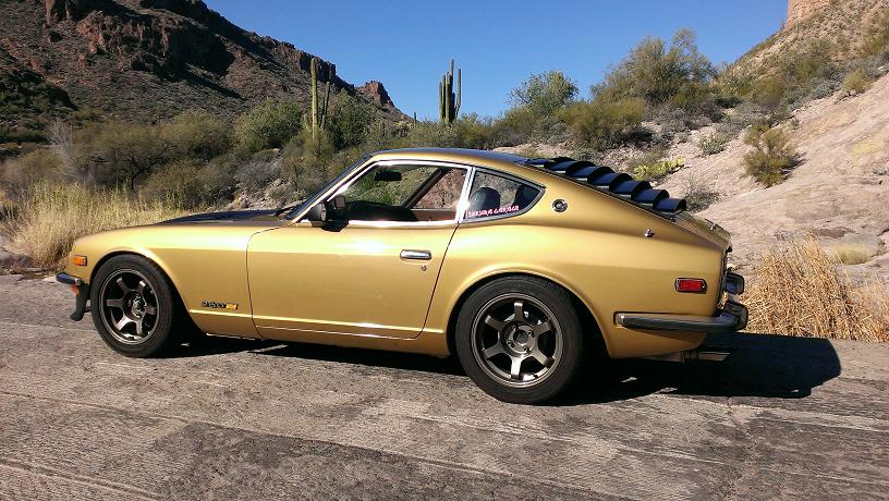
Here's a pic of Goldie, but I don't know how that helps you... "ride height" is gonna depend on more than your set of coilovers. You need to tuck wheels and tires in there. This car has 225/50 16's - my Son has told be the size and offset of these Rota Grid wheels about 200 times - I just never remember (I know they're 16's, just not the width and offset... Offset here would be sorta important to know.) The lip on the wheel arches front and back have been folded back ("fender rolled" - not with a fender roller but the result is basically the same). The frame in the center of the car is about 4.25" off the ground and it's fairly level. I have about another 1.5 (maybe 2) inches of drop left in the coilover. (I'll never use it, I think this is too low...) Maybe that helps. --------- Mack says the spring rates on this kit are 6K front 5K rear (that's about 335# in the front, right?). I didn't really understand the OP's "bouncy" description - that's not how I'd describe mine at all. I like the feel - quite firm but not too harsh - I'm old and drive it every day.