cgsheen
-
Posts
676 -
Joined
-
Last visited
-
Days Won
9
Content Type
Profiles
Forums
Blogs
Events
Gallery
Downloads
Store
Everything posted by cgsheen
-
260z L28et Build (first build newb)
cgsheen replied to Co0ke's topic in S30 Series - 240z, 260z, 280z
Welcome to the 260 TURBO Club! Do yourself a favor though and scrap the stock engine management from the start. You'll have to do some re-wiring to mate the ZX engine with the 260 frame anyway... Spend that time and effort learning about using the MAF, TPS, Coil & Ignitor, Chopper Wheel, ECU off an early (distributor type) VG30E (Maxima, 300ZX, Infiniti M30). The stock A18 ECU will run the L28ET much better than it's original ECU and flapper-type AFM. -
S12W Rotor / Caliper Spacing
cgsheen replied to duragg's topic in Brakes, Wheels, Suspension and Chassis
The Z31 vented rotor doesn't get moved outboard, it gets moved inboard by the spacer to get it centered in the caliper. If you spaced the caliper farther inboard, you'd also need to space the rotor that much farther inboard as well... Wheel fitment depends entirely on the wheel and usually moreso how the "hub" of the wheel is cut. My Son's wheels fit the Toyota calipers, my 16x8 Rota Grid's needed a spacer - not because of the spokes, because of the hub design... -
-
WIRING!!! The connectors in these cars are way past their "sell by" date. Much of the copper wire in your harnesses will be oxidized. The ECU is in a place prone to be dripped on by windshield leaks. The first thing to check and clean (and check and clean again) is wiring and connectors throughout... (especially when you have something "intermittant")
-
CAS signal is the same. Plug from the CAS is the same. I used an '81 harness and ECU on my '83 motor with the CAS in the dizzy - ECU didn't care... Should work the other-way-around. The wiring to the injectors is fairly simple: There is one Red +12V constant supply - I believe it splits somewhere near the intake manifold to the six injectors. Solder a resistor into each of the six supply wires... They're large - usually in a ceramic casing.
-
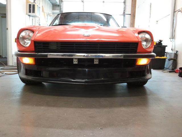
Mine's from MSA, I just used the stock front valence mount points: 2 bolts in the fender, 2 (or 3 if you like - I did) bolts in the headlight bucket. We mounted my son's on his '76 the same way.

-
Sorry, using the stock ECU there will never be a "running perfect" without all the parts it's expecting to be there. It's just not that smart. You may be able to "fiddle" with what's left and get things closer... It make take quite a bit of trial-and-error. If your plan is to get even further away from stock, you need a different engine management system - one that's smart enough to keep up with your changes.
-
L28ET swap 240z runs rough won't take throttle
cgsheen replied to motomanmike's topic in Nissan L6 Forum
The injectors (all of them) are supposed to have 12V - and due to their nature (the injector is a coil, a solenoid) they will show the same voltage on each side when power is applied. The ECU fires the coil (injector) by grounding one side for less than a split-second... The proper tests are that they all have voltage (my L28ET has constant voltage to the injectors - they are wired direct to the BAT through a fusable link as per the FSM circuit diagram), with the connector removed they should have approx 2.8 Ohms resistance across the two pins, and a noid light should respond (light ON when the injector should fire) when the engine is cranking. -
Is your A.A.C. functional? It supplies bypass air at idle to correct the AFR. If it has no vacuum it'll cause a rich condition at idle. The stock ECU can't really correct the idle AFR without it.
-
L28ET swap 240z runs rough won't take throttle
cgsheen replied to motomanmike's topic in Nissan L6 Forum
Howler - be sure to get me info if and when you've got that engine management package together. Motorman - With all the time (and now $$) you've got into that, it's a shame someone didn't steer you towards a Maxima / Z32 / M30 "A18" ECU (MAF, Coil, TPS, chopper wheel). Much better engine management than stock on the L28ET. It's rewiring the harness for sure, but the benefits (AND not having to troubleshoot the stock system) are immense... -
There is a way to test the CAS. It's electronics needs power and ground. The FSM describes the wave forming circuit. The CAS produces an "ON" & "OFF" pulse (signal) with every tooth passage. You can test the 120 degree signal by cranking the engine and testing the voltage on ECU pin 17 or 8. When the tooth passes, it should read voltage (5 volts maybe), otherwise no voltage. The 1 degree signal will be harder with an external CAS, but the engine could be spun by hand (plugs pulled, socket wrench on the crank pulley bolt to turn the engine slowly by hand). Testing for the same voltage spike when a tooth passes. Maybe you could see it while cranking, but I don't think so. ( This is easier with the CAS in the distributor - you can pull the dizzy and spin it by hand to test. ) I don't remember which pin is which, but one is the 120 degree signal and the other is the 1 degree signal. I'll check this tomorrow on my L28ET...
-
You don't need the ECCS Analyzer. For everything it tests, the FSM shows an alternate way to test the wiring and the component using a simple electrical meter. All the information you need to test every ECCS component is right there in the "EF" section... EF-31 describes the operation of the C.A.S. and how to adjust it's position. EF-33 TPS operation and how to adjust EF-41 Power to Injectors and how dropping resistors are wired EF-60 Component and harness tests (to be done with electrical meter)
-
Then you missed the 2 bolts in the bottom, next to the block - they go up through the bracket into the compressor front and back. Once those 2 are out, so is the compressor.
-
Buying advice...would you bite? help asap!
cgsheen replied to motorhead87's topic in S30 Series - 240z, 260z, 280z
Well, the car is worth what it's worth to you. I'd say: keep looking. We just bought a '71, very straight frame, floors and frame rails intact, for less than $800. Rust remediation is a PITA unless you have the time, experience, & tools (and/or $$$). Buy a solid foundation, the rest is fairly easy. Most AZ cars are fairly rust-free, but there are an awful lot of cars here that came from somewhere else... -
Here's the EF section - 1981 Turbo Supplement. It has all the ECCS information, wiring diagram, testing and troubleshooting information. EF.pdf
-
There is no "switched ground" from the ECU. There are 4 wires to the CAS: red = +12V (battery voltage through EFI relay), black = GND (to intake manifold with others), white & green = 1 degree & 120 degree signal to ECU.
-
Dude... Do you have the 1981 280ZX Factory Service Manual? Do you have the (1981 280ZX) Turbo Supplement? The wiring diagram is right there. A. The C.A.S. gets NO "ground signal" from the ECU. It's just grounded to the engine along with a bunch of other grounds - including some ground connections to the ECU. (The ground for the CHTS, Air Regulator, & etc. are all connected to this particular ground as is most of the sensor wire shielding...) - Just make sure the C.A.S. has a good GROUND. - Check it has +12V (battery voltage) at IGN ON (power to the CAS comes from the EFI Relay which powers the ECU at pin 35 and several other sensors & devices) - CAS wiring is: Red +12V, Black GND, White & Green are the 1 degree / 120 degree signal to the ECU (sorry, don't remember which is which) B. NORMAL operation for the ECU: Green LED comes ON (stays ON) at IGN ON. Green LED goes OFF at engine crack or engine start. Green DOES NOT COME ON AGAIN until ECU tries to go into "closed loop" mode. In closed loop the ECU is monitoring the O2 sensor and constantly adjusting the injectors to ride the edge of "just Rich" and "just Lean". The LED ON at this point indicates the engine is running rich. The ECU does not even try closed loop mode until the CHTS reaches a certain temp - several minutes after engine start. - I don't believe the ECU LED will go OFF if the ECU isn't getting a CAS signal. (disconnect your CAS where it plugs into the ECCS harness (by the thermostat housing), crank the engine, see if it stays lit or goes out upon cranking) - check your spark. There will be NO SPARK if the CAS isn't working. The ECU creates (sends) the spark signal to the Ignitor/Coil. It can't (won't) if it's not getting a CAS signal. C. You CAN use an '82-'83 ECU with an '81 harness. You have to remove the dropping resistor pack AND REWIRE the connector OTHERWISE the injectors have NO power. (the resistor pack has one +12V "feed" that runs to 6 different resistors then to each injector. 7 wires. Hook them all together.) The '81 Turbo Supplement says the injectors are powered through the EFI relay at IGN ON. In the '82-'83 they are powered constantly from the battery through a fusable link. D. ALL this information is in the FSM (and several places in these Forums). E. There is a COMPLETE TROUBLESHOOTING GUIDE in the FSM. F. It's easy to follow. G. It you follow the guide, you'll find EXACTLY why your engine won't start (without having to replace parts that don't need to be replaced). I have a working 1981 280ZXT ECU. Just removed from my running L28ET a couple of months ago when I swapped to the M30 ECU. (Heck, I have the whole thing - ECU, Harness, AFM, Coil/Ignitor (no CAS)) I also have a 1983 280ZXT ECU. PM me if you want to spend money on parts...
-
Nope. That's what it's supposed to do. +1 for getting and reading the FSM...
-
Me too...
-
Over 3/4" thick???
-
If you have a stock O2 sensor, use it until you're ready to start tuning. If you have to buy one - don't. Put the money towards a wideband. I use an MTX-L, VERY nice unit for the price (~$170). Gauge & Controller in one, Top quality components, Bosch wideband sensor screws right in (and a replacement sensor costs less than a M30 heated O2 Sensor...), and it has a simulated narrowband output to feed your ECU.
-
CHTS or water temp sensor?
cgsheen replied to rickyellow zee's topic in Trouble Shooting / General Engine
CHTS has the same type 2-pin Bosch connector that the injectors use. In reality, the sensor is the same (has the same temperature curve and resistance values) as the water temp sensor - but my water temp sensor (Nissan calls it a "Thermal Transmitter" - for the cockpit gauge) has a different connector (single wire) than the CHTS. The Thermotime Switch looks a lot like the CHTS, but can't be used as one. It's merely a switch that "turns on" at high water temperature - it tells the injector fan to run when you shut the engine down. I don't use mine - no "hair dryer" on my turbo swap... The CHTS will have a resistance value that changes with temperature (chart is in the FSM). The thermotime switch will only show "open" or "closed" circuit when tested with an Ohm meter. -
I'm sure you know not to apply power if any part of the case is in contact with the circuit board. Denting probably happened in shipping? Still, I don't know if I'd trust the circuit board not to have, or develop problems later - have stress cracks, affected a solder joint, etc... If you'd plugged it in to test it without taking off the lid, it probably would have fried. Hmmm...
-
Sorry, I'm with the girls on this one... The center section needs to be a different color. I'm with you on the Corbeau's though.
-
Take the lid off and look. Unless you know someone with a running RB25DET using a stock ECU you can test it in...