JMortensen
-
Posts
13742 -
Joined
-
Last visited
-
Days Won
68
Content Type
Profiles
Forums
Blogs
Events
Gallery
Downloads
Store
Everything posted by JMortensen
-

Dual 7.25 clutch install issues
JMortensen replied to JMortensen's topic in Gen III & IV Chevy V8Z Tech Board
They are ARP flywheel bolts for an LS1. Not seeing shouldered bolts here: https://www.google.com/search?q=ls1+flywheel+bolt&oq=ls1+flywheel+bolt&aqs=chrome..69i57j69i59j69i64.4751j0j4&sourceid=chrome&es_sm=122&ie=UTF-8#q=ls1+flywheel+bolt&start=0&tbm=shop&tbs=vw:l -
Dual 7.25 clutch install issues
JMortensen replied to JMortensen's topic in Gen III & IV Chevy V8Z Tech Board
The flywheel does fit the pilot on the crank, but it didn't fit in the dish of the stock flexplate, so they told me to get the Quicktime plate. It has a thick spacer on it that is as deep as the pilot on the crank, leaving the ACE flywheel loose and unregistered. I like the shouldered bolt option, but I think I'd have to open up the bolt holes to do it because there isn't enough room around the bolts for anything but a super thin shim, and there's the risk that the holes wouldn't get opened up on center. I think right now the safe option is to either replace the flywheel with something that fits the stock flexplate and reorder the bearing again (which I would like to avoid) or to do a couple more shear pins with everything mounted on a fake crank pilot. -
Dual 7.25 clutch install issues
JMortensen replied to JMortensen's topic in Gen III & IV Chevy V8Z Tech Board
Had an idea. Make a faux pilot to put the pieces on, then drill a couple new holes for shear pins. Maybe even make the shear pins permanent by welding them to the flex plate. -
Spring Question With Shortened Struts.
JMortensen replied to Chris Duncan's topic in Brakes, Wheels, Suspension and Chassis
I had some friends who used to do something similar with 510s. They wanted smaller OD springs, so they'd use 240 stuff, and they'd cut the spring perches off of a 240 and weld them onto usually 280ZX struts (disk upgrade that fits under 13's and has the right spindle angle). If memory serves they welded the perch so that there was no preload. If you went the same 2 inches lower, you'd get back to stock, but that's pretty light springs. Stock in front of a 240 is something ridiculous like 83 in/lbs. Could you do the old Chevette spring upgrade? That's low buck, if you can find a Chevette... -
Installing an ACE dual 7.25" clutch. First problem I had with it was that the back of the button flywheel didn't fit inside the dish in the stock flexplate. Called ACE, they said get a Quicktime flex plate. Did that, then realized QM had sold me the wrong HRB. Got the Tri-Lite, and took measurements to get the correct bearing. Got the bearing, now I'm going to bolt it all together, and I have another problem. The button flywheel is loose on the studs. I put the 7/16" dowel in to try to center things up, the flywheel still has .013" movement on the studs. Not sure what to do next. I think my options are to try to center it and then torque the FW bolts down, have the ACE flywheel machined to fit inside the stock much thinner flex plate (which will mean that my measurements are wrong again and I'll need another bearing from QM), or ??? Here is a video I made of the problem. What would you do? https://www.youtube.com/watch?v=WAhhHiROFO0&feature=youtu.be
-
My impression is that you can only like one thing per 24 hours.
-
Weirdly, I found that it was MUCH easier to adjust camber with the weight of the car on the plates than after jacking it up.
-
Torsional Rigidity Testing, 280Z
JMortensen replied to Chris Duncan's topic in Brakes, Wheels, Suspension and Chassis
This comment here set my brain in motion. Sorry if I rain on your parade here, not my intent, but I really think you've got some problems with your testing. Seems to me that your test rig reinforces the front strut towers from twisting, and it actually might do that job quite effectively. You've got the lower control arm stand in and the strut stand in welded together and bolted to what looks like a 2x6 presumably pretty heavy walled piece of steel. That assembly is fighting the torsion that you're putting in, and I would think that it is adding a lot of stiffness compared to stock. Add to this the idea that you put the torque into the lower frame rail in the back, not the strut tower there, and your test is more of the lower frame rails and rocker's ability to resist torsion when aided by the front reinforcement. I dunno. Maybe I'm wrong, but the more I think about this the more I think you need the actual suspension members in there and you need to put loads into them, not the frame rails themselves. You're putting torque into the chassis, but you've also reinforced it at the same time. My suspicion is that you'd end up with MUCH lower numbers with the front end tested at the hubs. Just looking at the "Think Fast" book again, he describes mounting the chassis via the hubs, and says: "The wheel mount blades should be very stiff, but only in the vertical direction. They should be flexible in all other directions so that the fixture does not artificially stiffen the car." Your front and rear setups look rigid in all but beam. I think in order to do this test and get really accurate results the suspension will have to be all metal to metal bushings. Your thread had me considering doing something similar, but my plan was to do it through the hubs. I have all monoballs and heims joints except stock front ball joints. I think even they would have to go in order to make this sort of testing accurate. -
Good to have you back Larry!
-
Yes. The fittings on most prop valves are 1/8 NPT. You can see the thread sealant already on the fittings from the manufacturer in this example: http://www.jegs.com/i/Baer+Brake/136/2000035/10002/-1?CAWELAID=1710912856&CAGPSPN=pla&catargetid=230006180000514967&cadevice=c&gclid=CjgKEAjwtZucBRD77aiiq_v4xnASJABkAg8J5Ni2G_JgF3gDAXjLw2F2msL4q5l48KMTWhsLfv3cYfD_BwE
-
ARP 2.5" is 63.5mm, but you'll need the 1.5mm lug nuts.
-
So you're using 3/16" line with 3/8-24 fittings on the prop valve end?
-
There was a BF suffix that meant Bubble Flare.
-
That's a great solution, but requires a level of modification that a lot of people don't want to get into. I like the bolt in subframe idea in that it (in theory) could be made to fit any stock chassis that isn't damaged.
-
If you want some other ideas for front diff mounts, might check out TSS fabrication. They do a lot of 8.8s into WRXs and EVOs, etc. He likes to integrate the front and rear mounts all into one piece. I think that's the way to go. https://www.facebook.com/TSSFAB.US
-
The hubs and brakes are different. If you swapped out all the 280 stuff for 240, you would be fine. If you just swapped the struts, there would be a few issues.
-
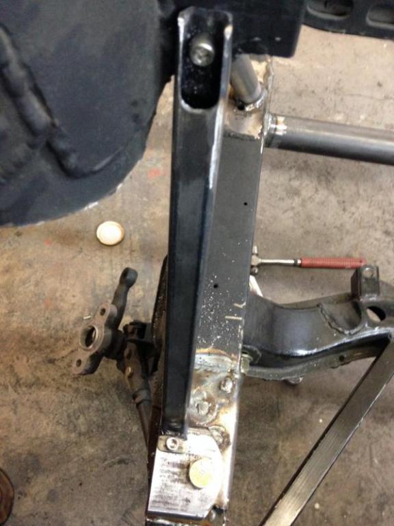
Made the braces from the bushing box to the STB mount today. Also notched the frame rail for steering shaft clearance. There was about 1/8" clearance before.

-
gland nut welded to strut tube
JMortensen replied to grillhands's topic in Brakes, Wheels, Suspension and Chassis
It was probably coming loose. If you're replacing struts, the new struts should come with new gland nuts. I'd be more worried about the threads on the strut housing. -
Something tells me that he wrapped it around a pole doing something other than putting to the alignment shop.
-
Ran across this today: http://www.summitracing.com/parts/afc-30030?seid=srese1&gclid=CjgKEAjwwPabBRCXo46OtM_RhGMSJACgCeqAA9DCl1Sw3lzo2cgYUD32oz7bxD9WADM-YcuqIU3-QPD_BwE It's a double adjustable AFCO strut for a Mustang. Because it's a Mustang strut it isn't compatible with a Z (has ears on it to attach at the bottom, but if that were available without the ears and just a threaded body, could screw into any of the adapters that people use for cheap Chinese struts. AFCO has a very good reputation with the Miata crowd.
-
10 minutes isn't going to destroy anything. You should be able to eyeball the camber and check toe with a tape measure and get it there without too much trouble.
-
Right front wheel hub failure at autocross
JMortensen replied to wheelman's topic in Brakes, Wheels, Suspension and Chassis
Might be that the aftermarket aluminum hubs (AZC, MM had one) are beefier at the flange where the studs attach to the hub (assuming that's where the problem was. Never heard of that one before... -
It's a road racing on sticky tires problem.
-
It's easy to pinch the tabs when you're screwing the case halves together. Point them in instead of out and that makes it less likely to be a problem.
-
Found a "soup can" brake duct on my car...
JMortensen replied to mattster03's topic in Brakes, Wheels, Suspension and Chassis
katman, who built a number of successful ITS Z cars, described the soup can ducting mod here probably 8 or 10 years ago. The problem is with solid rotors most Z's have the duct hitting just the inside of the rotor. This mod allows air to get to both sides. And yes, it does need a hose to the front. The existence of that part on your car doesn't men that it was owned by an idiot.