
heavy85
-
Posts
1227 -
Joined
-
Last visited
-
Days Won
2
Content Type
Profiles
Forums
Blogs
Events
Gallery
Downloads
Store
Everything posted by heavy85
-
I'm sorry but boys that's just fugly. Body panel alignment appears to be off ... by inches. The Mercedes emblem is completely pimpin '80s gansta wearin around your neck kind of random poser stuff ... and the scoop in the front? Maybe you have to see it in person to understand? Cameron
-
 Katman - You mean rollgcage no? Shouldn't rollbar be far enough back to be out of the way? PS - sorry to threadjack Thanks Cameron
 -
Chassis stiffening ideas
heavy85 replied to heavy85's topic in Brakes, Wheels, Suspension and Chassis
Donor is an '02 Z28 and it'll pull three wheels by jacking in one corner without noticable deflection - it's actually a PITA because that makes it hard to put on jackstands but anyway .... on to my car. It's a Cali car and is totally solid. NO rust in the frame rail nor anywhere that I can find and I've looked (OK just light rust under the battery but very light). Scraped all the tar paper off the floors, just took off the front fenders, etc. Only place is the rear doglegs were replaced in the early 90's but seem solid now. There are no signs of any kind off previous accident but the frame rails are pathetic as they are so bent up it seems someone must have jacked it up with a little bottle jack or something about a thousand times on every square inch of the rails. This is why I am replacing the rails because otherwise there is zero rust on them. Otherwise I'm just trying to stiffen up things why it's appart for the LS1 swap without adding a cage. Jon - see Jeff's pic for what I'm talking about out back. Thanks Cameron -
Chassis stiffening ideas
heavy85 replied to heavy85's topic in Brakes, Wheels, Suspension and Chassis
Jon - look at your SFC and see they end at the factory cross tube (well it's really a channel welded to the floor) that runs side to side in the car. This is where all the SFC I've ever seen end. Now follow that factory cross tube outboard about 5" or so and you will see the rear frame rails start to go back. I'm just suggesting to connect that cross tube to the rear rails. Back in that area the factory LCA are in the way which is why I show that piece angling out. Now in general I dont seem to be getting my thoughts across. I do understand efficient load paths, triangulation, etc. Background: Both my daily drive Focus and the LS1 donor Camaro are so stiff that if I jack from one corner three wheels come off the ground (assuming it's balanced). On the other hand if I jack one corner of the Z only that one corner moves and you can visibly see twisting of the chassis through the door and hood gaps changing. Also notice that if I place jack stands under the frames rails at the base of the firewall that the front end sags quite a bit. My thoughts: It seems to me that it's relatively easy to stiffen the front and rear ends which I plan to do but then how do you stiffen the middle to connect the two ends and stop this sag / twist. This is not a dedicated track car so I am not going to put a cage in it. It also seems to me that the second best way would be to put a big X across the door opening to effectively connect the front and rear ends together. But then I would need a quick release steering wheel and it would be a real PITA to get in and out of and again it's not a dedicated track car. So again IMHO the third best choice would be to strengthen the rockers as the 'backbone' that connects the front to the rear. Adding material to the top and bottom of the rockers effectively increases the section height and therefore moment of inertia and therefore stiffness ... at least that's my thoughts. Cameron -
Chassis stiffening ideas
heavy85 replied to heavy85's topic in Brakes, Wheels, Suspension and Chassis
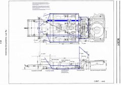
The SFC have to bend out because the rear control arm is in the way preventing it from going straight back all the way to the rear rails. The bar that looks like a door bar is the 1"x.065 square tube that welds to the top of the rocker flush up against the lip where the door seal goes. Another similar tube runs along the bottom edge of the rocker. Both then join in the front to a 1 1/4"x.065 round bar that goes to the upper frame rail. If you look at the side view the thinnest and therefore presumably least stiff part of the car is the bottom underneath the door opening. The roof provides a good deal of stiffness and a cage would provide a lot but I dont want a cage. Welding the doors shut duke of hazzard style would also stiffen this are up a lot but that's not going to happen. The idea with the 1" tubes on top and bottom of the rockers is to reinforce the rockers to make the center of the car stiffer. Hope that's clear? Thanks Cameron -
Please critique. Main idea here is to add 1"x.065 square tubing to both top and bottom of rockers to increase the section height and therefore stiffness since I dont want to add a full cage for head knocker reasons. Also extend SFC all the way back to the rear frame rails since all I've seen stop at the rear cross tube which is offset from the rear rails. Really trying to minimze weight since this will be mostly an autox car with only occasional track use. Biggest thing I'm still struggling with is what to use for the SFC as I dont want to cut the floors (I dont really want SFC at all but my rails are so bent up I might as well extend them all the way back). Also still debating in my head if the additional braces to the firewall are really needed since there is the tube in the wheelwell that connects the rockers to the strut horn. Thanks Cameron EDIT - it's so small I dont know how to make any bigger but it's in my album. My pics are either way to0 big or way too small This might be more useful: http://album.hybridz.org/showphoto.php?photo=11271&cat=500&ppuser=9862
-
-
Yeah what's with the foam and rivets. I see weld in there so it's not in lieu of welding?
-
Will Z06 exhaust manifolds fit?
heavy85 replied to heavy85's topic in Gen I & II Chevy V8 Tech Board
Bummer on the Z06 manifold as they look real nice and seem pretty cheap on e-bay. This is in regards to an '02 LS1 into a '72 240 and I'm most likely going to build my own mounts. I've also read in an old post that the f-body manifold will work if you re-orient the O2 sensor bung so that counters what's stated above? Also read that the C5 manifolds dont work which again counters what's been said so far. More I read the more conflicting info I run across. So what headers / manifolds other than JCI and JTR are people using? More I read the more confused I get because people tend to leave out key things like which year manifold or which brand 'shorty' header etc. Sad thing is I'm just getting started and already a little lost in poor and conflicting data. Cameron -
I know this has been asked before but the only post I found someone was flamed for asking and the answer was simply no but with no explanation. So anyone tried this and can confirm. Trying to save some $ over aftermarket headers if this would work out. Thanks Cameron
-
I've got a warmed over L28 (shaved head, mild cam, tripples, etc) that takes a bit of extended cranking to start when cold. This year I've only driven it to autox race which is about once a month. Start it which usually takes a couple attempts with several seconds duration each time, drive ~70 miles, restart it about 12-15 times in which it usually catches quickly, drive home ~70 miles, let sit for a month, do it all again. I keep getting worried that with such little charge time for the amount of cranking that the battery should be getting weak but it's held up fine all year with no charging whatsoever ... well except the stock Datsun alternator while the engine's running. I'm running an Optima red top so my experience may be a good data point for what you're looking for. Cameron
-
Pics: New CrMo-rollcage for my 240z
heavy85 replied to mull's topic in Brakes, Wheels, Suspension and Chassis
Comment on those is at least on my '72 the area where you show them mounting to the floor is very thin. I'm talking about the horizontal package tray which is spot welded to the real floor below. Looks like the mounting plates go on top of the package tray and not the more substantial floor underneath. If I were you I would cut out the package tray in that area and tie into the floor beneath. On mine the package tray metal is so thin (and not because of rust) that I can easily wiggle it back and forth by hand. To me the package tray seems to be an afterthought to provide a place to hold luggage etc and is not actually structural. Play with it and see what you think. Cameron -
What's everyones opinion of the JTR trans crossmember?
heavy85 replied to jakeshoe's topic in Gen I & II Chevy V8 Tech Board
Not if the angles are in the same direction. What I'm saying is if for example the trans is level and the diff it angled up say 2 degrees then all is well as long as you set it up such that each end of the driveshaft has one degree of angle to it. Therefore the two ends dont have to be parallel just have the same angle. Cameron -
What's everyones opinion of the JTR trans crossmember?
heavy85 replied to jakeshoe's topic in Gen I & II Chevy V8 Tech Board
Not quite. True the angles need to be the same but the input and output shafts dont have to be parallel. Cameron -
Looks nice ... except for the sunroof ... and supermutt. Only thing I would be scared of is what's under all the undercoating as it looks thick. Under the carpet wont necessarily show anything either since all you see is the tar mat. I would definitely poke around with a screwdriver to make sure there are no hidden treasures. Cameron
-
Rear groundcontrol coilover rattling
heavy85 replied to nazar's topic in Brakes, Wheels, Suspension and Chassis
My EMI camber plates do this - well at least the passengers side does. Reach around and feel the top of the strut when you hit a bump and you can feel the top move up and down slightly. I'm pretty convinced mine is most likely from the spherical bearing moving up and down very slightly in the race but it could be the bearing itself is a little worn. Thanks Cameron -
I believe the whole front wheel/suspension broke and hit him in the head - this is why they now have tethers on them. He was going VERY fast and bottomed out - which is also why they limit the minimum ride height - at which time you lose air flow under the car and therefore the downforce and the car spun out of control. Had the suspension been steel or carbon it would have failed either way at those speeds. Look at the recent really bad Indy / IRL (dont remember which) wreck where the driver survived thanks to the very strong carbon cocpit. Like all materials composites have their limitations such as fracture toughness mentioned above but also can be much stronger, and especially stiffer than metals. It's kind of ironic in that a high end carbon fiber composite part should sound like metal if you tap on it. Cameron
-
moving the steering linkage. anybody have pictures?
heavy85 replied to LamboZ's topic in Fabrication / Welding
The '02 Camaro I'm parting out has the factory set-up with an intermetiate steering shaft with no support what so ever. Steering column / u-joint / intermediate shaft (just hanging in the air) / u-joint / steering rack. Obviously I was a little surprised when I saw this. Cameron -
Removing front core support
heavy85 replied to LamboZ's topic in Brakes, Wheels, Suspension and Chassis
Not exactly but sort of. All the loads are imparted into the chassis originate in the strut towers and crossmember (well except the swaybar but assume that is probably relatively little) so the most efficient way to strengthen the chassis is from the strut towers back. In stock form there are no strut bars so the upper radiator support is probably providing a lot of side to side strength. So if you were to make a beefy strut tower brace in addition to beefy lower support then the upper support should be able to be removed with little drama - especially for a street car where you are not really trying to optimize things. Just very softly mount the radiator and I would think you should be fine. This is all of course without regard to impact protection which I can't really comment on. Basically I agree with what Michael said. Devil is in the details so I think it's really all in how it's implemented and if done properly should be fine. Cameron -
Above (except I dont think you need 19) plus 12 mm wrenches for driveshaft bolts, 22 wrench (I think) wrench for diff to mustache nuts, lut nut wrench, prybar - two if you are taking the stub shafts out, and most importantly jackstands. I never get under a car without it being on stands. Oh and ideally a sawzall to pull off the exhaust depending on where it's routed but that's more of a convenience item. Cameron
-
Sorry, I was looking at one of the pics backwards. Was referring to how the front side transitions to a point where the back side is squared off. Not saying there is anything wrong with the back but the front being tapered down to a point should help transition the stress into the tower nicely. Cameron
-
Thanks John - just what I was looking for. Two more Q's though. First do you remember what thickness plate you used - I'm thinking somewhere about 12 to 16 gauge but hard to tell. Also did you re-inforce the back side of the firewall at all? Thanks again Cameron PS: I see you ended up re-doing the strut tower plate to better transition the stress between the raw pics and the painted one. PPS to Jon: Yeah I already thought about that based on some FEA I've seen at work on a similar type of system
-
What are you using to control your electric fan?
heavy85 replied to Zmanco's topic in Miscellaneous Tech
-
Bump - John you out there? Thanks Cameron
-