NewZed
-
Posts
6700 -
Joined
-
Last visited
-
Days Won
72
Content Type
Profiles
Forums
Blogs
Events
Gallery
Downloads
Store
Everything posted by NewZed
-
Not a Wolf expert, or even Magasquirt but the concepts shown in your diagram from mobythevan look right. The bottom HEI unit would be the "ignitor" controlling the ground circuit for the coil, and the top HEI unit would be for "processing" the signal from the variable reluctor in to a from that the ECU can use. Note though, that the 280ZX distributor's "match box" has essentially the same function as the GM HEI module. So if your distributor has the match box intact, it already has what you need. It's possible also the Wolf ecu can handle a variable reluctor signal directly so you may not even need that HEI module to process the reluctor signal. The Wolf products are pretty high end. It might even have its own internal ignitor. Who told you that you need an ignitor?
-
This wiring diagram is pretty good. http://www.atlanticz.ca/zclub/techtips/wiringdiagrams/F77ZCAR-WIRING1.pdf Shift your focus to the module under the dash, by the fusebox, and things will make more sense. You could even mount the Crane box there, since the wires you need are all in place. Replace the 77 module with the Crane box, and the single pickup with the optical unit. Use the meter to confirm connections. Use the red and green wires to connect the optical pickup to the Crane box. Leave the blue wire attached to the coil negative, it branches on the way to the ECU and tach so it needs to be there.
-
This has come up before. I actually called the company and talked to a guy who explained that they assumed all Z cars used the CV. Said they were going to fix the database but looks like they didn't. Or maybe they got halfway, I think it listed all the way back to 70 before. Or maybe they fixed their side, but the database is still wrong. Pretty sure I talked to GSP but it could have been a different supplier, working from the same bad database. These bad databases seem to live on forever, like the ones that show 71C transmissions for the 240Z's and 280Z's. Anyway, the fact that the ZX's use 6 bolt wheel flanges, and the Z's use 4 should be enough to see it won't work. Same part number, different flanges.
-
You might have one of the two pickup models of distributor and ignition module. What's under the distributor cap? If you have two pickups, try the 1976 wiring diagrams. Don't forget to disconnect the original ignition module under the dash. And the blue wire also feeds the ECU and the tach, it's not just the coil ground. Did the engine ever run with what you have? Adding new parts to non-running parts can make an undecipherable mess. This won't make you feel better, but it's not sticky-worthy because it's not really that hard. You're just replacing one electronic ignition module and trigger system with another. You could do the same with a GM HEI module. The GM module might actually be more robust than the optical pickup of the Crane. These links might help - http://www.cranecams.com/uploads/instructions/9000-0700_.pdf http://www.triumphspitfire.com/images/cranemanual.pdf
-
Can't seem to get my 260z to redline
NewZed replied to zedsn's topic in S30 Series - 240z, 260z, 280z
It's been over six years since the post you're replying to was posted. Truth be told...the source of your "bog" was an almost empty tank? The weak baffling of the 280Z tanks is known. Most recommend refilling at 1/4 tank or higher if any hard cornering or acceleration is planned. -
Similar to this "My car was slowly running worse and worse,.... it idled fine... when I tried to drive the thing, it still felt like crap." That's almost too much detail.
-
How far not? That would be a clue about where it's hanging. Where's the picture of the inside of the diff? Through the hole where the circlip is.
-
Don't roller rocker arms use a different cam profile formula? Since the contact point between cam and roller moves up and down as well as back and forth. So you need a cam grinder that does roller cams also. Maybe it's common and there's a simple conversion formula.
-
Cut your stock springs and get some KYB's. KYB's have worked for many people with lowered cars.
-
The 1974 manual is pretty poorly done. Lots left out and what's there is hard to grasp. Open the Body Electrical chapter and read about the Starter Interlock system. Find the red emergency button in the engine bay and give it a push. Your starting system may be locked out. Probably why the PO added all of those wires. You can't go on though, just connecting wires and listening for clicks. Eventually your misery will be ended when the car catches on fire if you keep working that way. If you take the time to learn what the engine needs to start and run you could wire up your own ignition system. The "custom wire" was a start but it needs a switch, as you've found.
-
Never mind. Got my b(e)ar(e)s backwards. Edit 2 - Now I realized I actually had it right the first time. Bare (minimum), not bear. Unless he's trying reach the standards of an actual bear. Anyway... What people are trying to tell you is that they've worked hard to know what they know and and that you, apparently, know absolutely nothing, like you grew up in the middle of a city and have only used mass transit. Not that there's anything wrong with that, but you are totally clueless and talking about doing things that require orders of magnitude more knowledge than you have! The transition from shiny magazine pages to reality takes lots of effort, sweat, and frustration! It's not easy! So, no matter how enthusiastic you are, you're going to waste time and money. The only question is how much!
-
Put a meter on the wire to the starter solenoid and see what voltage does. If it goes to zero, you've lost power to the solenoid probably back at the switch, If it drops to around 11 and stays there after the engine stops, something locked up. The starter's still pushing, just can't get it done. If it starts at 11 then drops to 6 or some other very low number, you have a bad battery. They can show good voltage but fail when they are loaded. I just went through that, even swapped in a spare starter I had. Then I put a meter on the battery and saw it drop to 6 volts after a few cranks.
-
PLEASE HELP, rear brake conversion issue
NewZed replied to Blob1620's topic in Brakes, Wheels, Suspension and Chassis
The engineer in you should take some measurements and post them. Maybe somebody out there will do the same. Be more precise than "about 1/8 of an inch". Look back at your posts and you'll see that there is nothing there that can help anybody help you. No numbers. The brackets all look similar. Your measurement tool and technique in the last picture is terrible. -
This is why the engine won't shut off.
-
This is not a plan. But, since you're just looking for a project, it doesn't matter much. Get that V6, tear out whatever's in the car you buy, drop that V6 in, and see what happens. There are a bunch of V6 options out there. You could call around first and see what the local shops charge for a rebuild. You might be over-budget pretty quick.
-
Recommend an engine. That's what he's looking for. "Modern engine" can barely be more undefined.
-
You can buy pre-flared and -fitted straight lines at the auto parts stores. Bend to fit. Any old used line you get will be work-hardened and corroded.
-
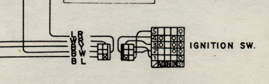
You have a mess on your hands. Be careful or you'll burn some wires and then you'll really be hating life, especially if you don't know electrical. Get a meter and learn how to use it so that you can check for power and continuity, to avoid shorts. There are diagrams and drawings in both electrical chapters that show where the parts are. But since the engine starts and runs you should leave those other parts alone for now. The TIU and the ballast resistor and the coil don't matter for your problem. Here's another source for an easy to use wiring diagram. http://www.atlanticz.ca/zclub/techtips/wiringdiagrams/74_260z_manual_wire.gif Here's a copy of the switch schematic. 260Z's are hard to work on. Looks like the wires switch colors somewhere inthe harness, and they don't show the B, A, I, etc. codes so you'll have to cross-ref to another schematic. A pain. L = blue, W = white, B = black, Y = yellow, R = red.

-
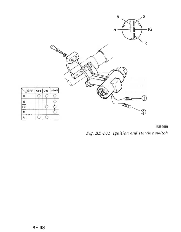
This might help. From Body Electrical. You might figure things out faster with a meter though. Not sure on the letters. Maybe B = Battery, A = Accessory, I = Ignition relay, S = Starter. Can't think of an R right now. Edit - actually those letters may not mean much. Looks like R powers the coil, and I powers the TIU, for example. But the schematics in the larger wiring diagrams use them, in a chart.
-
Lots of inconsistency here. If you don't know one, you probably don't know the other. Check out the wiring diagram in Engine Electrical. http://www.nicoclub.com/FSM/260z/ The red wire might be for a relay to help the switch. The 260Z's are known for a starting problem. " It appears someone soldered a red wire to the black and yellow wire and attached it to the starter." Also notice you're writing is getting weaker. Weak thinking = weak writing = weak results. Best to keep the effort level up, everywhere.
-
plus the engine doesn't shut off with the key. Doesn't sound like it works "just how it should". I'd focus on the switch.
-
To your knowledge, did the engine ever shut off, using the key? In other words, did you buy a problem or create your own? Probably had the wiring converted to internal voltage regulation and needs a diode on the L wire.
-
Sounds like your flex-plate is broken or torque converter is bad.
-
You can check for voltage at the switch terminals (the solder posts on top of the switch) and at the dimmer switch. To see if power is making it through, but not getting grounded. That would at least narrow it down to source or ground. I had a power switch that had just dried out (the little fiber board that holds the wires) and got loose. You can bend the tabs back and open up the switch to clean the contacts. Then bend the tabs back extra tight to make sure good contact is made. You didn't say if "cleaning" means just spraying with Deoxit or spraying and working the crap out of the switch. If it's been sitting a while you have to work it.
-
It's not more versatile, it's easier to understand. The important components are epxosed and easy to comprehend, like the vane inthe air flow meter. More air = more vane movement = more electrical signal to the ECU (simplified) = more time that injectors are open = more fuel for the engine...etc. The distributor has mechanical timing controls. Parts that move. Easy to understand and learn from. Compare that to a hot wire mass air flow sensor and ECU timing control with a crank angle sensor. You'll be connecting wires by color with no idea why.