NewZed
-
Posts
6700 -
Joined
-
Last visited
-
Days Won
72
Content Type
Profiles
Forums
Blogs
Events
Gallery
Downloads
Store
Everything posted by NewZed
-
possible jammed injectors.
NewZed replied to Metric Killerz's topic in Trouble Shooting / General Engine
What's the other problem? -
Here's a little...

-
I was going to offer you second gear from my trashed 5 speed but whoever broke it wore the dog gear pointss down to a lean-to shape from the original peaked, before the shift forks broke and the adapter plate bearing balls came out. Don't forget to check the leading edge of the inner splines/teeth on the coupling sleeve. If the dog teeth are beat, they might have some damage also.
-
Some sites have a "similar topics" list at the bottom of every thread. Essentially an effort-free search for the OP based on the words in the posts. Maybe the site could be programmed to respond with an automatic reply with those search results. A variety of snarky comments could be computer-generated for the amusement of others. Maybe even with sound and video. This would remove the personal tone of the "have you searched" replies from individual members, but still get the new member on the right path. After a certain number of posts the auto-response could be turned off.
-
Might be in one of your other threads, but it's not clear what cam you're using. Turbo cam or NA? If it's the turbo grind, why not run the stock factory spec.?
-
'75 280Z Alternator Upgrade (to ZX)
NewZed replied to Tennesseejed's topic in Ignition and Electrical
That is true. If you're replacing both VR and alt, money is saved, if you only need to replace one, probably not worth it just replace the bad part. Interesting tip on the pickup alternator. I browsed through RockAuto and found that 90 - 95 pickups (Edit - with the VG30 engine, the 2.4Ls were at 60 amps) seem to have the same shape, with a pully instead of the ribbed belt, but a different electrical connection,. But they are 70 amp, so for a little wiring work you could gain 10 amps on the high end with a bolt-in swap, and some rewiring. That's probably a better value since wires will be spliced anyway in the swap. Easier than swapping pullies on the Maxima alternator. It should probably be THE alt swap to do if anyone is going to do it instead of the ZX swap. I couldn't find a reference to a 95 amp alt though. To cd1105's post point - he's already in it and just trying to make it work. -
It might be interesting to put some blueing on the gear synchro cones and see the wear pattern of the new synchros before you put it together. You mentioned lapping in the drivetrain.com synchros. Went out and looked at a box of parts from a destroyed 80-83 5 speed I have and the 1-2 shift fork is aluminum with brass wear pads. It's the only trans I've had apart so don't know if it's normal or not.
-
'75 280Z Alternator Upgrade (to ZX)
NewZed replied to Tennesseejed's topic in Ignition and Electrical
Typically the W/R wire from the back of the alt terminates at the starter lug, after feeding the fusible links along the way, the same point as the positive battery cable, and charges the battery through that point. If you only have your positive cable connected to the starter and no other wires to battery positive, then your battery won't get a charge. But your engine shouldn't start either since you'll have no excitation current to the alternator. But if you only have the EFI supply connected to the battery pos., through the green fusible link, then the engine might start, but not charge, unless it self excites at higher RPM from residual magnetism. That would probably show as low voltage at the battery, but regular charging voltage at the fusible links or alternator post. What else is connected to the battery positive post or the starter lug? -
The thermotime switch is supposed to heat up through an internal resistance heater and break the CSV circuit after so much time on Start, or after the engine has heated up. Time or thermo. Not saying that they always work, just that that's why it's there and what it's supposed to do.
-
Almost had it. I looked for that but was on the wrong page. Here's a drawing. They might even have the u-joint although they don't call it out separately. Might not be meant for taking apart. http://www.courtesyparts.com/300zx-parts-z32-1990-1996/genuine-nissan-parts/power-train/328-transmission-shiftcontrol/-c-882_883_953_970.html
-
It does look like a u-joint, but why would there be a u-joint on a "tranny bracket"? How about the u-joint for the steering column instead - http://www.courtesyparts.com/300zx-parts-z32-1990-1996/genuine-nissan-parts/steering/488-steering-column/-c-882_883_991_995.html
-
L28et swap RICH in the >10 AFR's, AFM at idle?
NewZed replied to SDgoods's topic in Trouble Shooting / General Engine
I guess you missed my point about the difference between actually "running rich" (too much gas, not enough O2) and high AFR numbers? The gauge is just showing you what's coming out of the exhaust system. What went is in inferred from the number. It's an assumption. No guarantee that it means what you think it does. Your mileage is a good indicator, but you didn't mention it before. Good luck. -
L28et swap RICH in the >10 AFR's, AFM at idle?
NewZed replied to SDgoods's topic in Trouble Shooting / General Engine
You haven't said if you're taking your resistance readings at the ECCS connector or right at the various components like the idle switch, AFM, CHTS, etc. It doesn't matter that the component measures right if the ECCS can't see it, or gets the wrong information. You could help your dilemma by measuring those three things, and others like air temperature, at the ECCS connector and reporting what you get. Start at page EF-16 of the 81 turbo supplement. And, to be sure, do you know that it's "pig rich" or does it just feel like it's rich. [Edited out - waste of words] Maybe the AFRs are a symptom not a cause. -
It's easy to pull from below but make sure you first get the car high enough to slide it out once it's on the ground. It's a pain to raise the car when the back of the engine is sitting on blocks. This book is a good read if you wanted some other views on things to look for. Has about a page on grinding and another on jumping out of gear. http://www.amazon.com/Rebuild-Modify-Transmission-Motorbooks-Workshop/dp/0760320470/ref=sr_1_1?ie=UTF8&qid=1359313881&sr=8-1&keywords=bowen+transmission
-
The early 280Z's PCV system allowed dirty blowby gases to deposit crud around the throttle blade. Nissan moved the hose in 77. I had a similar problem as yours on my 76, with the RPM hanging high after everything got warm. I fixed it with carb cleaner and Scotch-brite. Remove the hose from the AFM to the throttle body and see what's in there.
-
doing a v8 conversion on a 280zx, couple q's
NewZed replied to gompers's topic in S130 Series - 280ZX
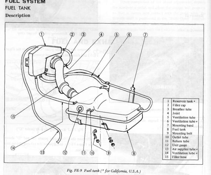
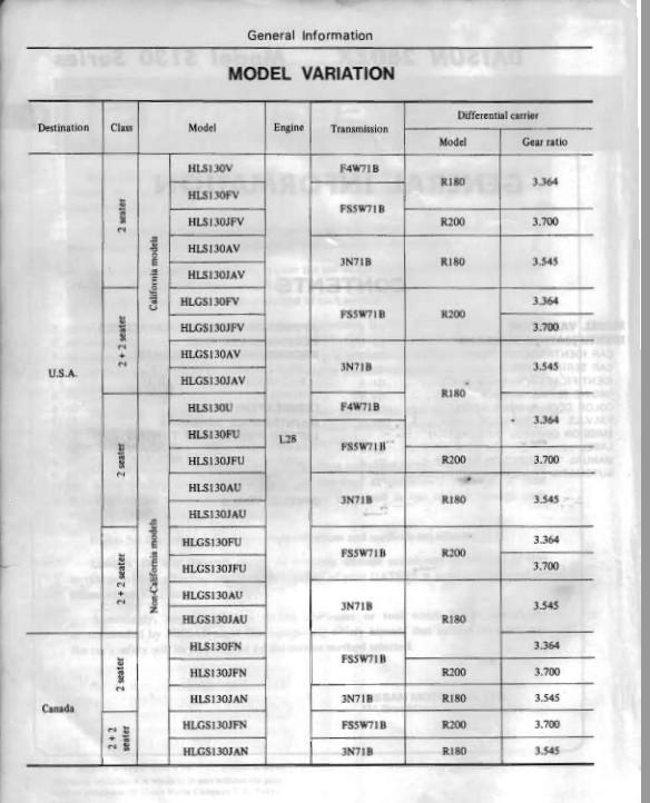
It could also have an R200. There appear to be 23 variants of body style, transmission and diff combinations for the 79, according to the General Information chapter. Nissan kind of went crazy. Some of them are 2 seaters with 3.7 R200's.
-
The 1971 S30 Supplement... file here has pictures. They might make sense to you since you have the car. http://www.xenons30.com/reference.html
-
Looks like someone bypassed the metal hose junction that used to be there for that hose. You can either get the piece and get things back to stock or stick your head up under the dash and just disconnect the hose and replace it. Here's a link showing what used to be there, depending on what year car you're working on (you didn't say) - http://www.datsunstore.com/heater-coolant-junction-tubes-7478-under-dash-p-1687.html a few more things to look at - http://www.datsunstore.com/7578-heating-dash-venting-c-203_206_362.html
-
L28et swap RICH in the >10 AFR's, AFM at idle?
NewZed replied to SDgoods's topic in Trouble Shooting / General Engine
A though - are you testing your TPS at the TPS or at the ECCS connectors? Better to test at the ECCS connectors so you know what the ECCS sees. As far as 0.3 volts, I think that the narrow band sensors jump rapidly from .2 V to .8 V when they go rich (low O2). But Ithink that when the mixture is way off, the sensors can foul and don't work right anymore. The wide bands apparently go the other way, in a more linear fashion, from high V to low V when the mixture gets rich. You're not using the same type of sensor for your AFR gauge and the ECCS are you? They're different. And there's a newer type of sensor that uses resistance, not voltage to calculate the ratio. You're probably right on the EGR effect, since there is no extra fuel added with the added EGR gas. I got my gases mixed up. I still can't see any reason for the AAC or the AAR to affect the fuel-air ratio. Good luck. At least you have a good reason to dig in to all of technology behind the system. -
L28et swap RICH in the >10 AFR's, AFM at idle?
NewZed replied to SDgoods's topic in Trouble Shooting / General Engine
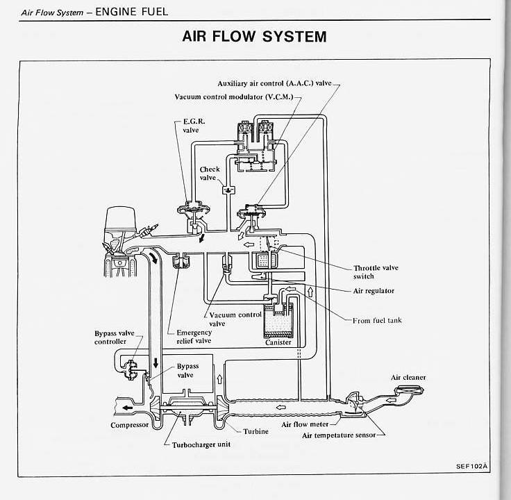
It might be a correlation, not a cause. The attached diagram shows that the AAC only bypasses the throttle blade. The EGR gas might affect the O2 reading, since it as adding O2 depleted air to the intake system, which is not the same "reference" air that the O2 sensor is calibrated to. The AAC and EGR system are tied to the same VCM. Looks complicated and the variables probably interact. Regardless, the 81 Turbo Supplement is a good document to study.
-
L28et swap RICH in the >10 AFR's, AFM at idle?
NewZed replied to SDgoods's topic in Trouble Shooting / General Engine
The AAR has no effect on the air-fuel ratio. It only lets air past the throttle blade, not the AFM. All air should pass through the AFM, if the AAR is plumbed correctly. 70 ohms is correct for the AAR, that's the resistance of the heater wire on the bimetallic strip. And the AAR only opens when the bimetallic strip cools off. Even so, it's only effect is on idle RPM, not AFR's. The AAC also only affects air flow, not air-fuel ratio, but through a different control mechanism. EGR will affect the amount of fuel, but it only dilutes both air (O2) and fuel equally. There's a great chart on page EF-49 of the 81 Turbo Supplement. EF-35 has a nice diagram of the inputs to the ECCS. 81 was the early days of the ECCS Analyzer though, so much of the FSM assumes it's being used. Makes it a pain to figure things out., but there's still some good clues in there. For example, at mid-throttle, mid-RPM on a warmed-up engine the ECCS should go to closed-loop control, using the O2 sensor. Maybe your O2 circuit is showing a constant lean condition and the ECCS is compensating. Might also explain the jerky behavior, and good perfromance under load. cg knows more about the closed-loop control since he's installed a few complete systems. Just a possibility. -
L28et swap RICH in the >10 AFR's, AFM at idle?
NewZed replied to SDgoods's topic in Trouble Shooting / General Engine
That's a good thing.
-
I feel like a parrot sometimes for saying it, but have you checked the FSM's? There are complete drawings and diagrams in the AC chapter. Look down in the lower right corner of the drawings for the drawing number and you might find that they used the exact same drawing. That would be a good indicator of sameness.
-
I would list the parts used to run the engine, to start. Is it a completely stock straight-across swap from a ZX turbo? What year? Any changes from stock? Turbo AFM, turbo ECCS, etc. Have you used the FSM to do some troubleshooting? Need more facts...
-
I get it. The "boss" being on the drive shaft side, to fit the hole in the flange. Thanks.