NewZed
Members-
Posts
6700 -
Joined
-
Last visited
-
Days Won
72
Content Type
Profiles
Forums
Blogs
Events
Gallery
Downloads
Store
Everything posted by NewZed
-
Well, that's a bit of an odd combo. Might be worthwhile posting in the V8 forum. I'd post the links to the other 2 writeups also, so people know what you've seen. You'll probably get some generic advice but how many people have done the LS block with a Z32 transmission? Actual experiences will be limited, I'd guess.
-
What engine?
-
Stumbling under acceleration
NewZed replied to endofzworld's topic in Trouble Shooting / General Engine
Sounds like an accelerator pump issue (not fuel pump). It a device in the carb that squirts a bunch of extra gasoline in when you "mash" the pedal. With a bad pump the engine gets extra air but not extra gasoline, and loses power as it leans out. Not a Weber expert but that's what I'd confirm is working right first. If the Weber's even use one. -
ZCAR noob looking for advice on potential car purchase
NewZed replied to jbaker7326's topic in Non Tech Board
You should examine closely and be suspect if this is a big deal to the seller. It's not really a big deal. The CL ad has many things listed which aren't really that significant. Makes one think that the seller might just be a guy with a car hobby who may or may not have known what he was doing. For $12,000 it would be reasonable to allow the car to be inspected by somebody who knows their stuff. At this point it's really just a list of parts and some nice pictures. Besides that, you'll be buying an engine management system and set of parts that will require some fairly in-depth knowledge. Megasquirt is nice but each installation is somewhat unique. If you have a problem, where will you go?, is a question to consider. -
Transmission crossmember frame nut possibly crossthreaded?
NewZed replied to Stunt's topic in S30 Series - 240z, 260z, 280z
Were it mine I'd drill right through the body/floor, find the drill bit sticking out inside the car, then drill a hole big enough to extract the bad nut and insert a new one. Do the work from above, not below. Just make sure there's nothing sensitive above before the first drilling operation. -
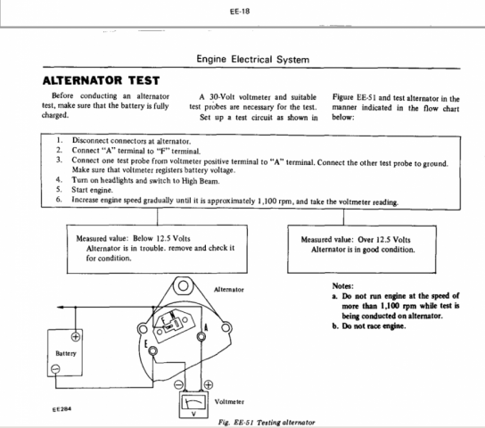
There's a whole 1/2 chapter on what to look for in the Engine Electrical chapter. Look for the Charge light, voltage at the T plug, run the tests. You'll need a meter.
-
ZCAR noob looking for advice on potential car purchase
NewZed replied to jbaker7326's topic in Non Tech Board
Actually, the CL ad just shows Rebello parts, no Rebello build. Pistons and bearings. Knowing who "rebuilt" it would be good. -
Stock Car Mafia's '78 280z LS2 Build
NewZed replied to Stock Car Mafia's topic in S30 Series - 240z, 260z, 280z
Seems more like just a sketchy pump. I don't know see how a small company can make their own pumps and sell them at the low volumes they must be at, for $89. And there's probably a reason that they're on sale, down from $179. Looks more like an inexpensive pump that they "made" their own, with some plumbing parts. I'm a cynic. Actually, the copy says they've been making their own for 10 years but doesn't say they made this one. http://treperformance.com/i-16517730-universal-external-inline-300-lph-fuel-pump.html An OEM pump for an older BMW 735 or Ford F150 might have the quality and capacity. Both external, same form. Bosch brand. The TRE 044 must be their version of the Bosch 044 - https://www.amazon.com/Bosch-61944-Universal-Inline-Fuel/dp/B003WL73OK -
Transmission crossmember frame nut possibly crossthreaded?
NewZed replied to Stunt's topic in S30 Series - 240z, 260z, 280z
That's a shame. You'll be parting the car out now? Failed in how to use a tap? Broke the tap off in the nut? The nut turned with the tap? Used the wrong thread pitch? Just kidding. You're not really asking a question anyway, just reporting a result. -
Camber change after 1.5" drop?
NewZed replied to mtnickel's topic in Brakes, Wheels, Suspension and Chassis
I thought that was a given. Urethane in front, rubber in back. -
Camber change after 1.5" drop?
NewZed replied to mtnickel's topic in Brakes, Wheels, Suspension and Chassis
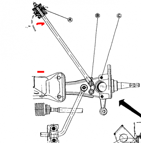
Ignoring bumpsteer (I think I know what that means) you can see that the flexible components of the front suspension can lead to toe-out as the wheels get pushed back. The steering gear can remain static, while the bushings compress. Braking must put some extra strain/wear on the steering gear also since it ends up under a higher tensile load. Urethane or solid bushings at the T/C rod and control arm probably help it last longer, and reduce toe-out. -
77 280z Starts (kinda), stops trying as soon as i let go of key
NewZed replied to Jp76z's topic in Ignition and Electrical
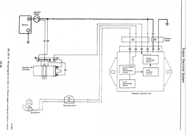
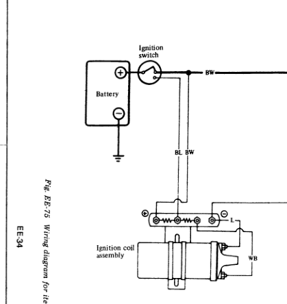
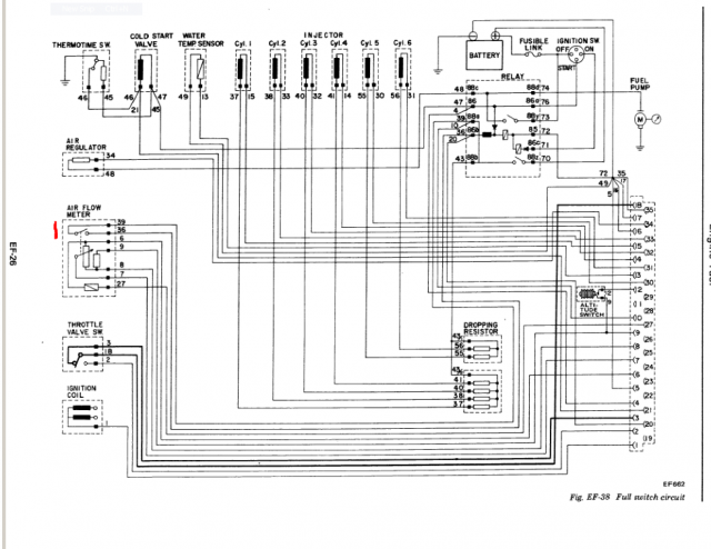
I would get in to the wiring diagram and see what has power at Start and what has power at On/Run. The ignition module needs its own power supply as you noted but you may have disconnected it. This diagram doesn't seem right since it doesn't show power to the module during Start (the short path (BL) is Start, the long one through the resistor (BW) is On) but it does show that W and BW at the module need power. Check those with the key at On. Maybe you have power there at Start but not On. The diagram is simplified, the ignition relay might actually be in the circuit. The full circuit with all components is in the link. http://atlanticz.ca/zclub/techtips/electrical.htm -
I think that this car is just an L6 with Nissan manual transmission and Subaru R180. The whole thing is kind of bizarre. I have a new theory - the CV axles are too short and pull out while driving. Hence the twisted axles and missing or broken clips. Doesn't explain the propeller shaft not moving while the car is in gear and engine running though. Maybe the propeller shaft is too short also.
-
77 280z Starts (kinda), stops trying as soon as i let go of key
NewZed replied to Jp76z's topic in Ignition and Electrical
There are two wires that power the coil - one for Start and one for Run. Sounds like only your Start wire is connected. Or you haven't addressed the fuel pump relay contact switch in the AFM. Usually the engine will run for a few seconds before dying if it's the fuel pump contact. -
L28 after small rebuild running REAAAALLYY rich
NewZed replied to BlueZed's topic in Nissan L6 Forum
Just curious. Don't see many members from Poland. The banana/bullet connectors are stock. You probably adjusted things out of spec. trying to make it work with all of that extra fuel. Good luck. -
The diff nose can't rise to hit the e-brake unless the rubber of the diff mount stretches. If you're stretching the diff mount rubber you should go with an RTz style mount. http://www.technoversions.com/DiffMountHome.html
-
How can the diff nose do anything if there's no power being transmitted to the rear wheels? You went from incomprehensible problems to hard acceleration with no explanation. This is the oddest thread I've seen in a while. You have three nice car, I have one old one. Why do I bother thinking logically?
-
280zx weird issues and my list of what I've experienced.
NewZed replied to Austing's topic in Nissan L6 Forum
Check your CHTS. It might be disconnected. You're kind of far back in the knowledge spectrum. You might spend some time reading the Engine Fuel chapters of the earlier 280Z's. They give excellent explanations of how things work. The later ZX FSM's are less descriptive. The concepts are the same. Ponder what the words mean. "Turn over" and "crank" are essentially the same thing. Way back, they used to use a crank to turn over the engine. "Fire" or ":ignition" is typically used to describe what you're hoping for when you crank the engine. Sorry to keep picking, but the words are what we use to convey information. Bad word usage = bad information. 8. The engine cranks and cranks but doesn't turn over -
L28 after small rebuild running REAAAALLYY rich
NewZed replied to BlueZed's topic in Nissan L6 Forum
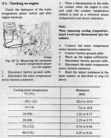
The obvious one is the coolant temperature sensor. Are you really in Poland, or just goofing? http://www.nicoclub.com/FSM/280z/ Engine Fuel, read the chapter. Also, you'll get better ideas if you are more descriptive than "playing". To some people that means hitting with a hammer,to others it's going through a complete calibration process. -
280zx weird issues and my list of what I've experienced.
NewZed replied to Austing's topic in Nissan L6 Forum
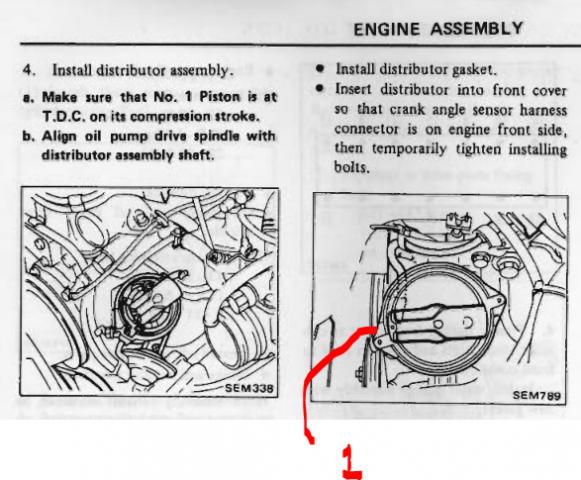
Haynes and Chilton aren't Factory. They're just simple notes on what might be right. "B. The distributor even though I'm getting spark maybe it's not working properly and yes I switched it 180 degrees and checked both ways to start it" You swapped your distributor around and back, but you don't need to do this. Just verify the notch and groove at the cam sprocket, and the damper timing mark at zero, and the cam lobes up (not straight up, just valves closed), and the distributor rotor pointing forward, all pointing or oriented the correct way at the same time. You can verify proper orientation of numerous parts all in one step. Get everything lined up and correct, then pick #1 on your distributor cap, put #1 in and fill the rest of the holes in the proper order and rotation direction. That's the procedure. The guys that throw their engines together and fiddle around to make them work know how they operate so they can do that. But if you're not clear on that, you need to start from a solid base. Good luck. -
280zx weird issues and my list of what I've experienced.
NewZed replied to Austing's topic in Nissan L6 Forum
You're not measuring anything. The only numbers in your entire post are "83 280". The injectors should not flood the engine. They might be shorted. Measure voltage at the connections with the key On. The method to confirm camshaft timing is described in the Engine Mechanical chapter - notch and groove, not "8. Engine was at tdc the cam key was straight up and the sprocket had number 1 pointing straight up". Correct firing order and rotation for plug wires is out on the internet somewhere. The method to confirm proper orientation of the distributor rotor is described in Engine Mechanical also (how did you replace the HG without seeing these things?). The NA ECU doesn't have any lights. You should put a proper procedure together, not a list of things from the internet, follow it, and write down what you measure.. Go through the Assembly subsection of the Engine Mechanical chapter of the Factory Service Manual. Start from scratch. Good luck. -
Check your Air Regulator. It's purpose is to let extra air past the throttle blade to increase the idle speed at cold start up. They can get gunked up inside, or the electrical connection can corrode. You should have about 1000-1200 RPM idle speed for a few minutes right after a cold start. You might just have too low idle speed.
-
Is this car new to you, or is it an old car with a new problem? You said that the engine runs fine when it's warm. Valve lash increases as the engine heats up. Checking lash would be a good idea. You might have a valve not closing when cold, causing a dead cylinder. That's very bad.
-
I got "motivated" 'cause you challenged my description of his motor as "new" (it's pretty common to see less than 10 miles on a new car's odometer), then took it further with the valve float comment. That's just how the world works...
-
So, back to the OP's issue - If the oil is clean you could just use what's in there. Probably full of ZDDP. Nissan factory spec. Drain it to make sure no water has condensed in over the years, although those cam lobes look like they've been pretty dry, then pour it back in. Then use one of the several oils recommended here for the first oil change. I'd dribble some oil over the lobes and rockers before turning it over to prime. The lobes look like they've drained completely dry of any oil.
