NewZed
-
Posts
6700 -
Joined
-
Last visited
-
Days Won
72
Content Type
Profiles
Forums
Blogs
Events
Gallery
Downloads
Store
Everything posted by NewZed
-
Looks like the Paraut symbol. I just picked this image off the interweb. Paraut was/is, apparently, an indirect OEM for Nissan. Paraut/Atsugi/Nissan, something like that. http://www.elautoparts.com/item.wws?sku=A4040-51981&itempk=86615&mfr=Paraut&weight=0.20 The wear on the other end of the arm is interesting. Isn't the tip supposed to fit inside the lash pad? Shouldn't it be worn across the full face? Looks like it's sitting on top of something else and it's worn a groove.
-
Post #11 here has an interesting picture of a way to directly address the load transfer problem (I think it's from JMortensen's Diff thread). More discussion also, can't agree with all of it, about what is strong and what is levered. Not sure how the guy's two piece mount came out in the end. Notice that the thread's from 2006. Ten years of development work on the short nose problem. http://forums.hybridz.org/topic/50794-my-q45-diff-mount/
-
Here's a not-too-old thread with many of the same actors commenting on the same general topic. Started on page 4 with SUNNY Z's pictures, but there's 19 pages total, plus a vendor's forum or group buy thread out there somewhere . http://forums.hybridz.org/topic/117668-the-ultimate-irs-swap-for-s30s/page-4
-
You misunderstood me in the first example - the arm is the nose. Or the nose is the arm...the lever arm. That's the thing about levers, you have to pick the right side, for reference. I thought I was clear which side I was talking about, but may have left out a few words. I talked about both sides, separately. Another way to consider it is that the assembly has what is essentially a hinge in the middle, of what should be a rigid beam. Which is what one the Q45 guys saw in his mount. Hinging where the nose met the mount, nothing above it to stop the motion. The cradle idea is great for the short-nose R200 and Q45, because they have nowhere to mount anything. I like the nose extension because it allows you to leave the car alone. Make the diff look like a long nose and use the long nose mounts. Arizona Z Car used the LCA arms as the cradle. Anyway, Oz Boy is probably working up some new thoughts It'll be interesting to see where he ends up. The first draft looks well-made, but may just not be right for the application. Probably work awesomely with my 150 HP (what they say) L6.
-
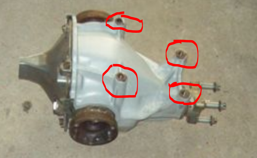
I had it right, I believe. The mount or body is essentially trying to hold the nose of the diff down. If the nose is long, it's easier to hold down. Just like trying to stop a spinning wheel by grabbing the spokes near the hub or out by the tire. Much easier out by the tire. The body and mount is trying to stop the diff from spinning. The longer lever arm of the new mount also puts more load on those two small bolts in to the body. Not only more load, but more of a twisting, unequal load. As the nose of the diff pushes up on the new longer lever arm of the mount it either pivots around the back bolt levering down on the front bolt, or you can think of the front bolt as the fulcrum levering up on the back bolt. Pretty sure people have had those bolts tear out or twist the metal (I wrote this on impulse from the first few sentences, I see that you've addressed the weakness of the sheet metal). SUNNY Z maybe. The original design pulls up on both bolts but with a longer diff nose applying less load. These short nose designs all kind of introduce two new weaknesses. No offense, the work looks great. The end result is just weaker than the original design, to be used with a much stronger engine. More power through a weaker mount. I've though about just building a steel framework that "adds" a long nose to a short nose . Basically converts it to a long nose. The new "nose" would need to be stiff and strong. Then a person could use the original long-nose mount area, both top and bottom (the crossmember). This GM diff might be amenable to that because it has four mounting holes. The Q45's don't have the structure to do it easily, they're round and smooth. I feel bad criticizing hard work. Everyone has been stuck trying to work with those four small holes.

-
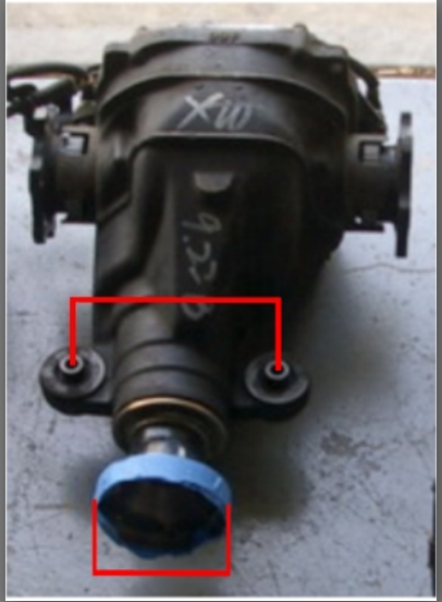
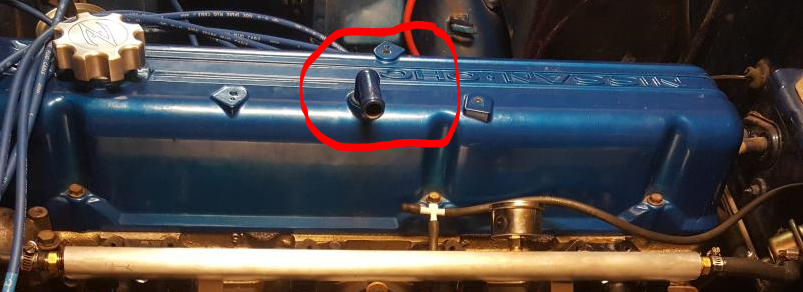
A little more help - the air space under the valve cover is the same air space that that breather tube connects to. The rocker area and the crankcase are the same space. If you're going to seal the bottom you need to seal the top also. Or just seal the intake manifold (where the PCV valve is and where that big tube ends up). You have a bunch of different problems to work on. Your 12% over-rate injectors are probably making up for the extra air. When you seal up the vacuum leak that you're working on, you'll have cut off that extra air. With no idle speed control the engine probably won't idle anymore. And you'll be running rich becuase the injector rates are higher.
-
It's been noted over the years by several, how the bushings allow the rear wheels to move forward in the wheel well. As the LCA bushings compress. There's pictures out there. Many people have problems when they install a short nose diff behind a high torque engine. There are threads out there about the Q45 diff, and the short nose R200. Maybe the R230 also. Leverage is the key. The shorter the lever arm, the harder it is for the mount to hold it down.
-
Follow the arrows.
-
I'd get a video of the front mount and diff nose, just to know all of the facts. If the axle axes are static (which they seem to be in the video) and the back of the diff is dropping, then the front of the diff has to be rising. Just saying, that's the way it has to be. Might just be taking up the elasticity of the front urethane or there's more flexing happening. This is different from what I first proposed. The short nose diff has a lot of leverage on those two arms used to make the front mount.
-
Apply the thumb.
-
I remember that one. Good to see you're still back in action. In your video it's hard to see what the front of the diff is doing. But you have elastic mounts up there also, it's probably twisting up and back, not too solid as I proposed earlier. And the leverage problem that everyone has who uses a short nose diff with the original holes for the strap mount. The nose of the diff is pressing upon a fairly long lever arm against the screws in the body. You might even be flexing those two arms also. I think that the front is moving allowing the back twist downward. The whole diff is twisting around the axles. And the tube you used for the rear bar seems to be flexing. The guys that run the Q45 diff have the same leverage problem on the front. The suggestions in your other thread about mounting directly above the diff nose probably still are worth considering. Just opinions...
-
You were on here before, right, a short while ago? A whole discussion about PCV systems and vacuum leaks? Hard to keep track of who does these things. Did you block the PCV valve on the bottom of the manifold? If not, the big hole in the valve cover will be a problem. Stick your thumb over it while the engine's running and see if anything changes.
-
Well then, carry on with the clutch control system, from pedal to fork. If it worked before you should be able to make it work again.
-
What does that mean? "Back".
-
Regardless, without ECU controlled idle speed, he needs a throttle body or blade bypass. The 280Z's had the bypass in the TB, the ZX's went to a hose bypass with an inline valve. Hard to get a good vacuum reading if the engine is about to die. He needs idle speed control. Set the idle speed then tune the engine.
-
What kind of throttle body (TB) is that? The 76 TB has a screw to adjust idle RPM,letting air past the TB. You might need to add a ZX TB bypass hose/valve setup.
-
Did you do these two things at the same time? That would change everything.
-
Here's a collection of information. Low impedance is old technology though so the choices are limited. If you're using dropping resistors you could remove them and go with high impedance. Some people use high impedance with the dropping resistors anyway, even with the stock 280Z EFI system. I have. It ran fine but I think I may have had current issues during starting (wouldn't start on cold days, but my battery is weak also) so I removed the resistors. Do you know the specs on the Adaptronic system? Maybe you don't need low impedance. http://users.erols.com/srweiss/tableifc.htm
-
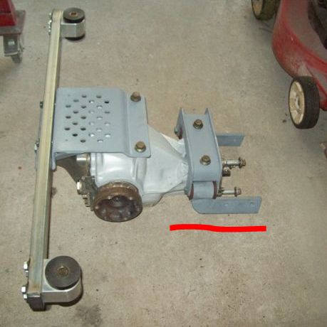
What kind of diff? The single bolt on the back mount looks unfamiliar. What's the front mount look like? The Arizona Z Car mount has brackets on the control arm pivots, yours doesn't seem to have those. Not really clear what you're working with. Looks interesting though. Did you build it or buy it? If you want to confirm that the bar is bending/flexing you could run a tight string across the top of the bar, from mount to mount, as a reference line. Distortion from the camera lens might be making the bar look like it's bending. If it's camera the string will look like it's bending also. All you can really say from the video is that the back of the diff moves away from the car body. But, if you look at how far the back of the diff moves and compare it to how far the bushing flexes, you can see that the back of the diff drops much farther than the bushing flexes. That's a long lever arm from the end where the mount is to the diff. Also, the hangers for the suspension brackets are tied directly to the body. So the "dogbone" is a reference point also. The back of the diff is definitely dropping and it can't do that unless the bar bends. Even if it twists on the bushings it still has to flex/bend also.
-
Stock Car Mafia's '78 280z LS2 Build
NewZed replied to Stock Car Mafia's topic in S30 Series - 240z, 260z, 280z
My mistake. Paint is plastic. Chemically and often physically. It's squishy. -
I see flexing of the bar and the bushings. The back of the diff is pulling down. Usually the nose pulls up but the rotational force is pushing down on the back at the same time. So the front is very strong now and the back is the weak link. Stiffer bushings without a stiffer bar might transmit more twisting to the studs. Fatigue could be a new problem.
-
The system worked. Could be the seller got caught with poor heat treatment like a couple of the guys on this forum did when they had stub axles made. The concepts are simple but getting things executed correctly seems to be difficult. Are you going to share the seller's ebay name so others don't get trapped? CFJ im[plied that Silvermine sells them but they seem to have a decent reputation for quality. They've been besmirched, indirectly, Make sure you get the clips installed and seated.
-
Looked like the bar was bending then springing back, kind of like the original bar was designed to, although it may bend much more with more torque. The mounting area, the studs, didn't seem to move. You didn't give any details at all about how the mount is made or what material it's made from.
-
Stock Car Mafia's '78 280z LS2 Build
NewZed replied to Stock Car Mafia's topic in S30 Series - 240z, 260z, 280z
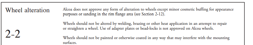
You implied that you had the wheel mounted on top of the paint on the brake drums. Generally, mounting surfaces should be clean flat metal. Burrs, dirt, grease, grime, paint should all be removed. I've been surprised that Nissan paints the flanges of the u-joint halfshafts. I scrape it all off if any is chipped. Tried to find a general internet reference and this popped up. Copied an excerpt. Lots of good stuff in the whole document, actually, even though it says it's for trucks and motorhomes. Load is load, a high performance Z probably hits motorhome loads.. https://www.alcoa.com/alcoawheels/catalog/pdf/ServiceManual-English.pdf
-
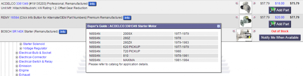
The 78 and on starters are gear driven, with an offset drive motor. They seem to be reduction starters, but I've never actually seen the gears or a description of their ratios so can't say for sure. They're not direct though, and it would be kind of pointless to offset them without taking advantage. It should lessen the voltage drop allowing more juice for spark and other electronics, as noted above. Never heard of the turbo car gear reduction starters, and the 78 + starters weigh less than the big motor direct drive pre-78 starters. So it looks like three different types are out there. At least one manufacturer describes them as gear reduction, for what it's worth. Picture from Rockauto site. Just a few more factoids.