-
Member Statistics
33118
Total Members2821
Most Online
All Activity
- Today
-
 Have you actually finished the installation of the track attack, or are just asking these questions hypothetically? I am somewhat familiar with this set and based on what I read it sounds like you have not installed it yet, is this correct?
 -
The hairlines weren't that bad, it was the handful that were going through the edge of the rotor that I was worried about. Friday marked my first return to the track in almost 2 years. Knocked off a bunch of rust, the car worked the whole time, and I made a couple changes that were impactful and improved the car. I went pretty slow, so y'all could enjoy some v8 sounds for longer than normal
-

My Z car log....small jobs done and fun things
A to Z replied to A to Z's topic in S30 Series - 240z, 260z, 280z
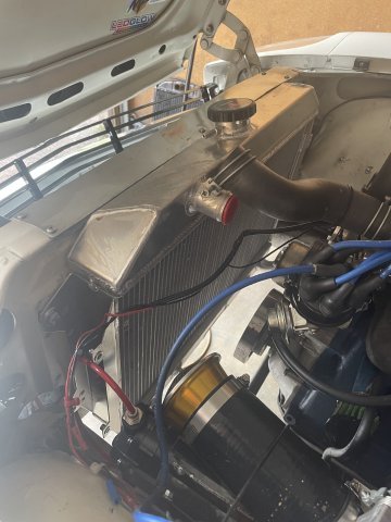
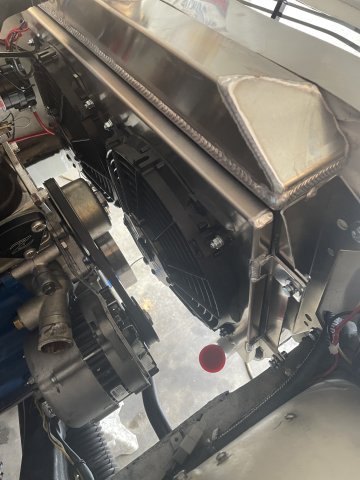
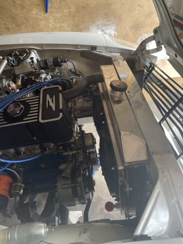
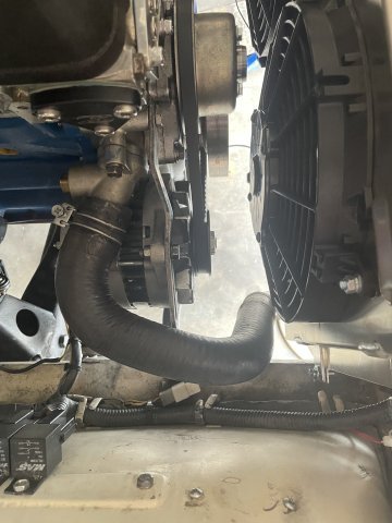
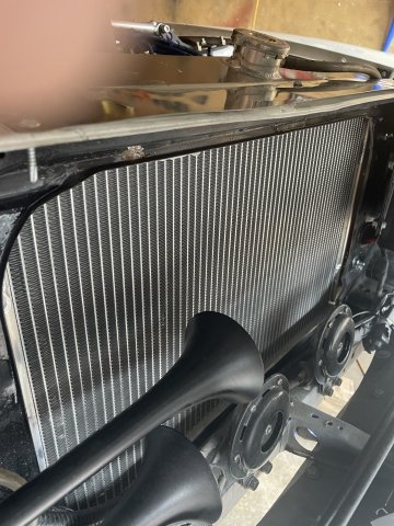
07-26-2025. Okay....radiator and fans installed and working. Waiting on the Thermostat sensor probe that is on it's way. 1 bottle of Water Wetter added. click below for video: fans work.MOV
-

A musician's therapist (The $300 Z)
Zetsaz replied to Zetsaz's topic in S30 Series - 240z, 260z, 280z
Actually now that you mention it, I'm 99% certain the tires were not mounted correctly initially. The marks are long gone though, so my friend did the best he could. But This is the last trip on these tires and maybe these wheels so I'm not too stressed about it. More annoyed by the vibration under light load right now. That said, at around 70mph there's enough load in most situations that it's almost nonexistent and any slight noise it was making from 45-60ish is completely covered up by the wind and even other cars' tire noise while driving. I think I'm gonna switch back to the RT top mount tomorrow morning before the trip and if it's not better I'll just deal with it. The T3 mount they switched to on their front diff cross member is just so tightly packaged that I feel like it might be amplifying some of the noise or actually causing it. Part of me wants to just go to stock or a Kameari mount and the RT snubber on top -
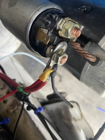
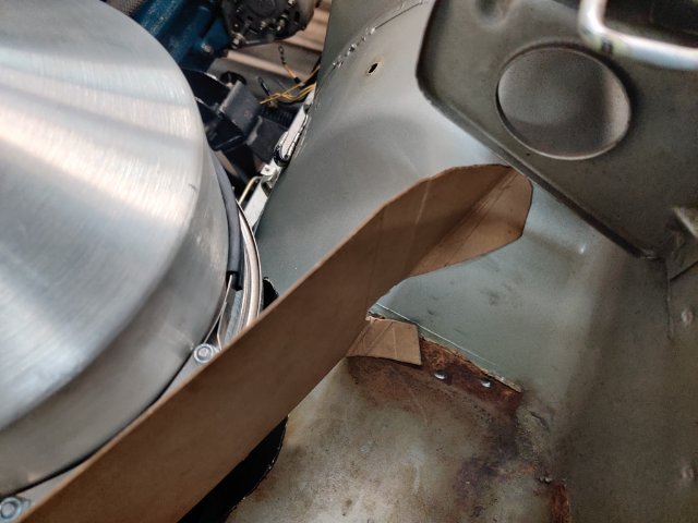
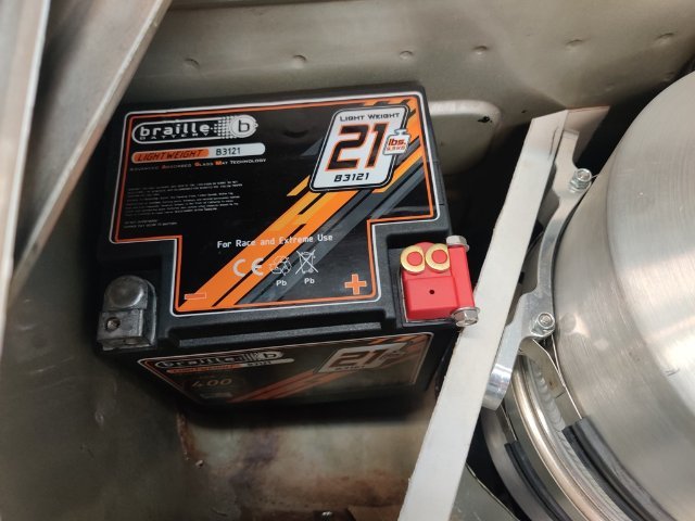
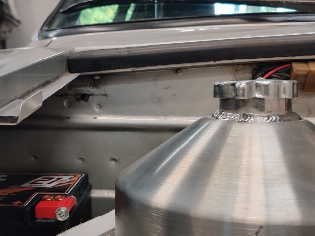
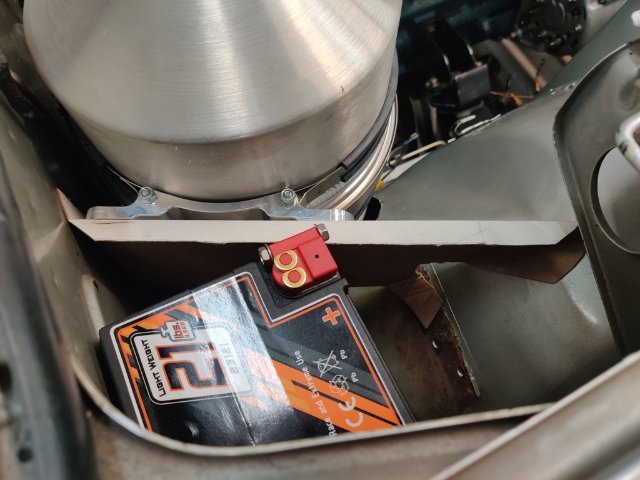
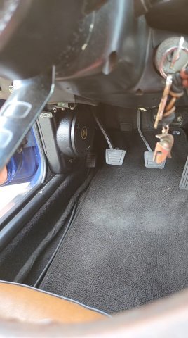
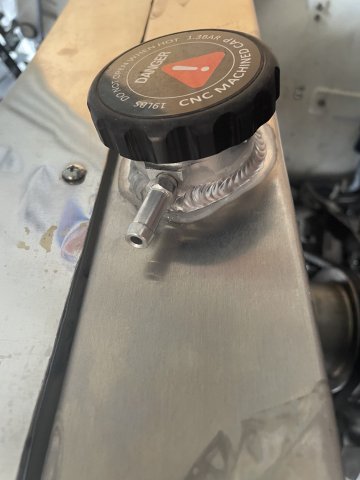
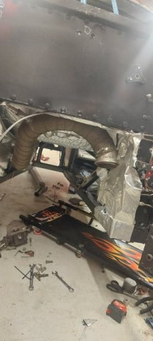
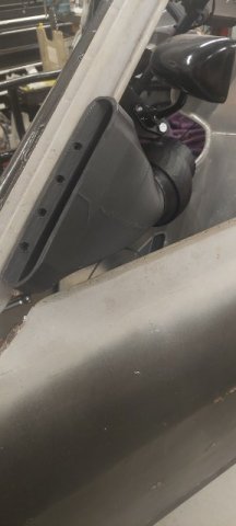
Today, I turned my attention to mounting the oil tank. Like the radiator, getting it to fit is quite a challenge. When placed against the firewall, the mounting brackets interfere with the brake and clutch hard lines, and the raised "ribs" in the firewall panel. I could space it out from the firewall, and still mount it there, but I came up with an alternative that I like. It will allow me to mount the tank far enough from the firewall to avoid wiring and hard lines and "ribs". I will be fabricating a mounting bracket which will connect diagonally from the firewall to the right inner fender. The final location of the tank will be just low enough to keep the filler cap from hitting the hood, and the drain will be located a couple of inches above the frame rail. Additionally, I purchased a Braille battery which is much smaller than the original. I will make and weld in a steel platform for it that will be similar to how it was done originally by Nissan. It will be a smaller platform, of course, but I will weld it to the inner fender in two locations and not to the firewall. At the top and bottom of the oil tank mounting bracket, I will put a 90 degree bend to add rigidity. I have some 1/8" thick 6061 aluminum I will use. Additionally, I have some aluminum angle. I may reinforce the top edge of the mounting plate with some of that. The bracket will be mounting to the firewall with two bolts (a reinforcement plate will be on the backside of the firewall), and to the front inner fender with two bolts. I may tie into the top edge of the oil mounting bracket in some way... to secure the battery in place. I want to be able to remove the battery without having to dismount the tank. So, that will be guiding my design effort for what I come up with to secure the battery in place.
-

A musician's therapist (The $300 Z)
Dat73z replied to Zetsaz's topic in S30 Series - 240z, 260z, 280z
Did they mount the tires correctly to minimize weights? I've had a couple sets of R comps mounted over the years which have balancing dots on the tire. I've found most shops don't know what the dots are used for 😅 - Yesterday
-

Fast Floridian's 240Z Track Build
FastFloridian replied to FastFloridian's topic in S30 Series - 240z, 260z, 280z
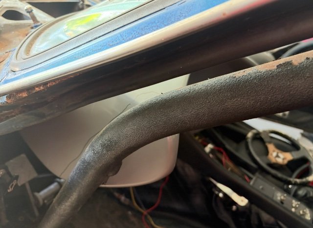
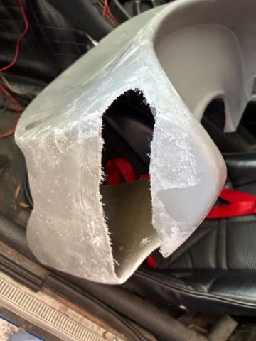
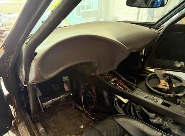
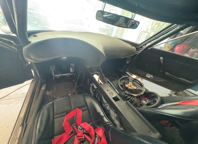
Started cutting on the dash to see how it will fit, roll cage goes through it. Now I need to mock up the digital gauge display and see how it will fit. Displays is bigger than dash think it needs to Poké above dash as steering column looks to sit too close below. Too hot out, done for the day.
-
Fast Floridian's 240Z Track Build
FastFloridian replied to FastFloridian's topic in S30 Series - 240z, 260z, 280z
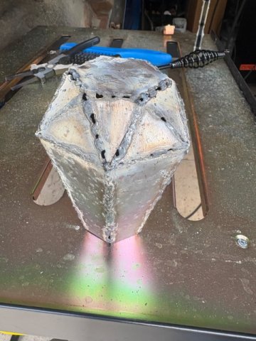
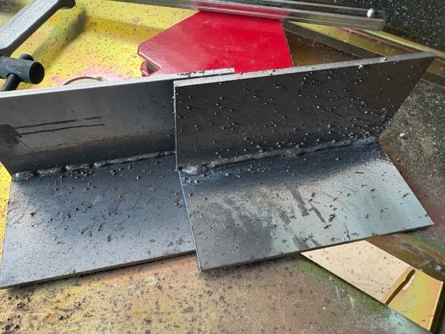
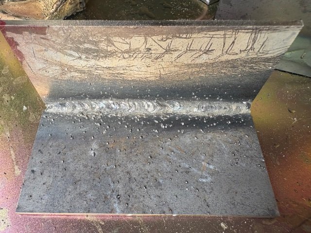
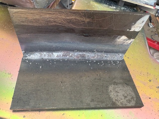
Started learning to weld, here’s my first tries last weekend and through today, about ready to weld on the car. Going to practice on some thinner stuff first to get more practice.
-
A musician's therapist (The $300 Z)
Zetsaz replied to Zetsaz's topic in S30 Series - 240z, 260z, 280z
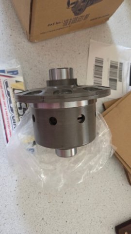
It was a good idea not to wait on rebuilding the 3.54 diff. The new LSD arrived weeks after I expected it and there's no shot I would have been able to swap it into the spare R200 before my trip. I'm excited to get this together in the winter though!
-
Another S30 Restoration from Japan- no English Subtitles This short video gives the viewer how restoration can accomplished even with a badly corroded body. Note that most of badly corroded areas can be replaced with aftermarket body panels( even wheelwell edges). Also, one must realize this work took over months of bodywork by a professional. Toolman
-

L28et powerband issue
Nicksturboz2 replied to Nicksturboz2's topic in Trouble Shooting / General Engine
lol you are correct sir.... I checked the wheel bearing and there were alittle loose on the driver side [normalish] but the pass side didnt feel right [probly needs new bearing} but I got it tightened up and took it for a drive..... night and day diffence. Ive been working on everything else it didnt even occur to me to check. so thank you. -
A musician's therapist (The $300 Z)
Zetsaz replied to Zetsaz's topic in S30 Series - 240z, 260z, 280z
Got the front speakers in today! Considering none of the speakers are big it's not particularly impressive, but it sounds alright for a 50 year old car. More incentive for me to go to a quieter muffler next year which I didn't get to do this time around. Got the tires balanced and was surprised just how poorly balanced these things are. My new Panasport spare only need 1/2oz, these needed... So much more I won't bother counting each. The vibrating I was tracking down is 90% gone and now I can't tell what's left of it. With the wheels and driveshaft balanced it's almost entirely gone but over 50mph I'm still getting some vibrations on very low load - so cruising speed. The moment push the pedal a bit for even slow acceleration it's gone and when I'm off the throttle it's also gone.
- Last week
-
Sounds like front wheel bearings. Your tires will wear out faster also.
-
Throttle body vacuum lines routing
socorob replied to Daniel13brx7's topic in Trouble Shooting / General Engine
So that goes to the vacuum port on the throttle body, the other one comes from the gas tank. Where does the 3rd one go to? I have an LS swap and trying to figure out hot to hook it up.
-
Throttle body vacuum lines routing
socorob replied to Daniel13brx7's topic in Trouble Shooting / General Engine
Someone got the canister off an old Nissan truck, I think a Frontier. It was newer and looked exactly the same. https://www.rockauto.com/en/moreinfo.php?pk=1002271&cc=1211050&pt=5180&jsn=606 Maybe it was off an early 90s truck? -
MichaelAMcDaniel joined the community
-
L28et powerband issue
Nicksturboz2 replied to Nicksturboz2's topic in Trouble Shooting / General Engine
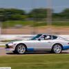
Wanted to give an update. she is fixed. It was the bosch 124 ignition module. The ground had corrosion under the connecter at the chassis ground and replaced the module. Also it now has a keyway in the ati underdrive pully and Im getting ready to install kameari twin idler and their perfromance oil pump.... I already installed the adjustable cam gear. she pulls really hard as its climing past 6k. I havent had the guts to keep my foot in it much past 6k but there really isnt any need to rev much higher anyway. mods list sense last post cylinder head.... I did more port matching and cc matched the combustion cambers had the head decked alittle more.... and I unshrouded the valves and polished the combution chambers.... also port matched the intake to the head/intake gasket hx35 now has a billet compressor wheel 2010 sti diff installed only problems Im having at the moment is when driving the car it wants to follow the grooves in the road but on flat road it drives perfect and the alternater doesnt charge under 2k rpm because of the ati underdrive pulley alignment settings are 2.5 camber 6 caster 1/8 toe in ride height 6in 17in rims 245 40 17 kumo v730 next im probly going to replace a the u joints but shes boosting and driving great. -
My Z car log....small jobs done and fun things
A to Z replied to A to Z's topic in S30 Series - 240z, 260z, 280z
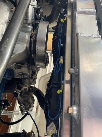
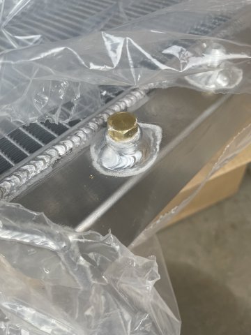
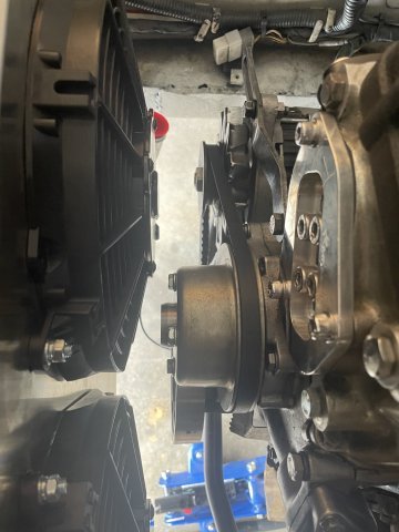
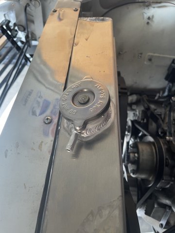
07-25-2025. I had a couple hours today, so I decided to see if the radiator would bolt in. Since June of 2021 I have been building my Z car. This is FIRST aftermarket part EVER to bolt right in. I didn't have to mod it at all. I was speechless. Granted, swapping the fans out to the SPAL fans required drilling and playing with it to get it done. However, I was able to drop the radiator and the fan should assembly right in. It is still loose, but it is there, hoses on, loose, but the idea today was......with a little time to see how far I could get it together, it literally just fell together. So "cubauto" on Amazon, there radiator for our Z cars goes right in! Now, the overflow tube on the cap was put on crooked, so I have to live with that, that is the only negative in an overall very nice looking package. Because of the size of my remaining port on the thermostat housing, using a sensor to turn the fans on and off isn't going to work. Being that my Z is just an around town toy, I will be turning the fans on and off via toggle switch. The remaining switch is 20A rated, but I ordered a switch that externally looks the same but is 30A rated to swap in. I will be feeding both fans with 10 gauge wire which is 30A rated and will forgo using a relay. 30 fA use and it will be basic, clean, and work. I swapped out the 19 lb radiator cap for the facotry 13 lb one for now. Pics follow. Good few hours today! Cheers!
-

1983 280zxt water temp gauge not coming on
jetmail88 replied to jetmail88's topic in S130 Series - 280ZX
wired thing is my dash is digital... -
1983 280zxt water temp gauge not coming on
jetmail88 replied to jetmail88's topic in S130 Series - 280ZX
Yep ! Looks just like this one !! I will make sure there's not a kink in the wire before I order it. Thank U very much jhm 🙏 -

IMSA GTU vintage racer build
clarkspeed replied to clarkspeed's topic in S30 Series - 240z, 260z, 280z
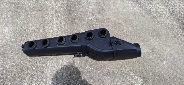
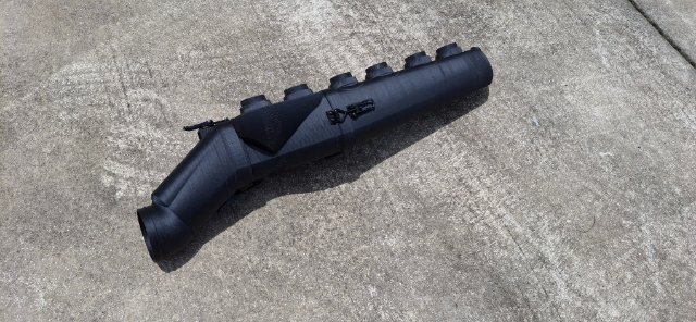
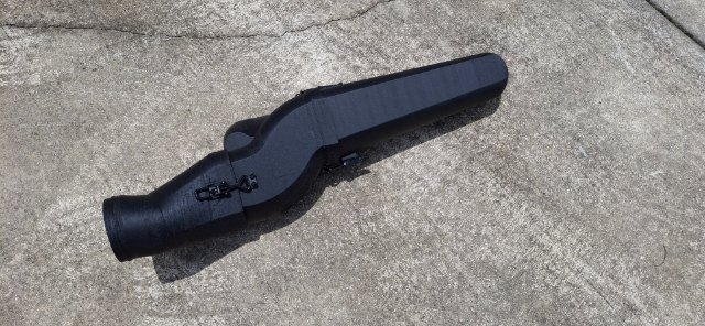
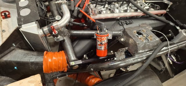
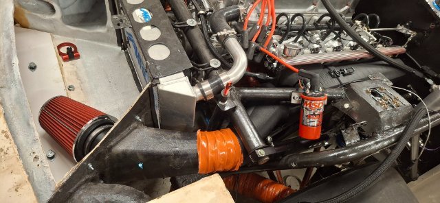
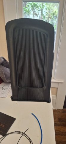
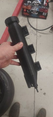
And finally the new cold air intake I 3d printed in nylon/cf
-
IMSA GTU vintage racer build
clarkspeed replied to clarkspeed's topic in S30 Series - 240z, 260z, 280z
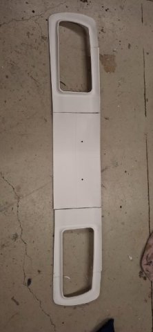
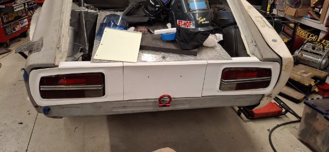
My first prototype of a printed taillight surround and final version. I printed in 3 pieces then laid fiberglass over the back to stiffen them and bond together in 1 piece.
-
IMSA GTU vintage racer build
clarkspeed replied to clarkspeed's topic in S30 Series - 240z, 260z, 280z
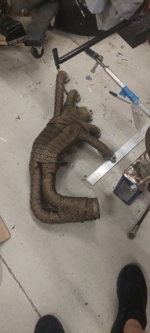
Header wrap and insulation
-
IMSA GTU vintage racer build
clarkspeed replied to clarkspeed's topic in S30 Series - 240z, 260z, 280z
Some more 3d prints
-
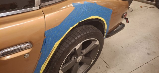
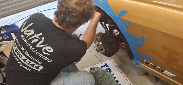
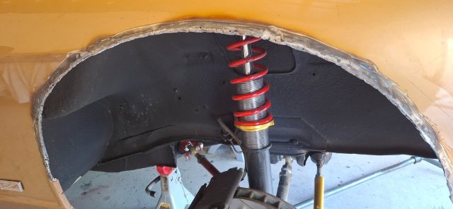
Finally we took some POR15 chassis black and painted the exposed metal. Under the flares it looks almost invisible.
-
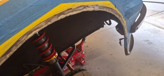
For the front's we bent a length of 3/16 rod and tack welded it in place. This stiffens the fender back to OEM or better. I have seen a cut fender wrinkle before when doing hot laps on a track. Weld and grind smooth.


.jpg.c007ffbe9bfabf6ba990513160d48805.jpg)


-
Who's Online 1 Member, 0 Anonymous, 1104 Guests (See full list)