zcarnut
-
Posts
820 -
Joined
-
Last visited
-
Days Won
3
Content Type
Profiles
Forums
Blogs
Events
Gallery
Downloads
Store
Everything posted by zcarnut
-
Yes. The “N” terminal of the voltage regulator feeds one of the two fuel pump relays. This is part of a safety feature that is needed when you have an electrical pump. When the alternator is rotating a voltage is generated at the N terminal of the alternator and voltage regulator. This is in case you have an accident where the engine stops but the fuel pump can still remain running and thus feed gas to a potential fire. See Fig. EF-15 on page EF-7 and Fig EE-29 on page EE-13 of the factory service manual. The later Nissan vehicles used an extra switch on the oil pressure sender instead of using the “N” alternator signal voltage. On my 260Z when I (like you) got rid of the interlock system and went to an internally regulated alternator, I elected to just bypass this extra fuel pump relay (I like using the electric pump to prime my triple Webers). However, I can not advise you to do the same because this a safety issue.
-
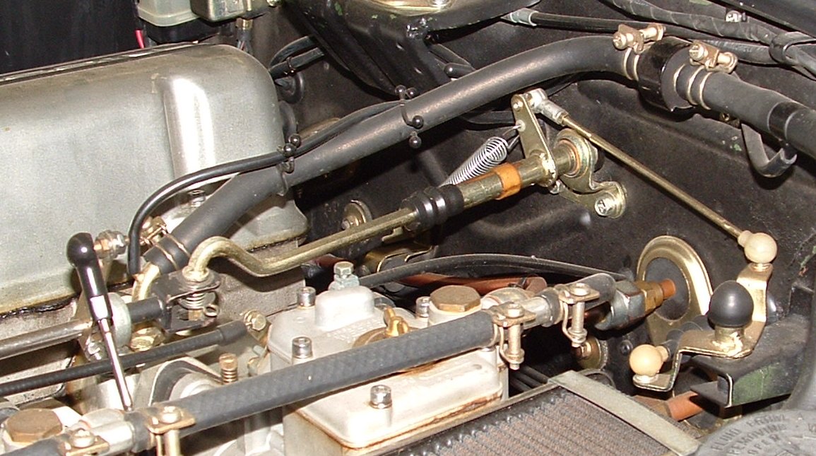
Is this close enough?

-
I am using the 260Z linkage piece. It's shorter than the 240Z one and it can be cut to the precise length. Sorry for the low res pic. It's all I could find right now without a lot of searching.
-
I don’t think the brown striped component is a resistor. Sure looks like a film capacitor. I would not replace it with a resistor until you know what you are doing. You could possibly damage the circuit. I think your best bet is to make a schematic of the circuit and also identify the part number of the IC you saw on the circuit board. Hopefully the IC is the LM2907 or LM2917 charge pump which were commonly used in the 1970’s for tachometer circuits. The IC could also be a simple LM55 or 556 timer. All analog tachometers use either a charge pump or a monostable (“one shotâ€) circuit triggered by the input pulse to drive the meter coil. Once you get the circuit drawn you can Google “analog tachometer circuits†and hopefully determine the correct resistor to change/adjust.
-
The 62/28 bearing I mentioned in post 4 is a deep grove bearing.
-
I ordered a 38335-N3220 in May 2009 and got it from my local Nissan dealer. John, are you ordering the correct number? It's 38335-N3220 and not 38335-M3220. I thought the "M" in your number was just a typo.
-
Jon is right. I had forgotten about the input bearing being rebuilt with ceramic ball bearings: http://forums.hybridz.org/showthread.php?t=130782
-
We have discussed this issue before John and here was my response: The R200 input bearing (Nissan PN 38335-N3100 or 38335-N3220) is a Koyo type 83601A. It is a single row deep groove ball bearing with dimensions of OD = 73mm, ID = 28mm and a length of 16mm. I talked to a Koyo engineer about this bearing a few years ago and he informed me that this bearing was specifically made just for Nissan. My suggestion would to use another bearing and have a collar machined for it so the combination could be used in place of the 38335-N3100 bearing. An SKF type 62/28 bearing has the dimensions of OD = 58mm, ID = 28mm and a length of 16mm. So you would require a collar with an OD of 73mm and an ID of 58mm and alength of 16mm. The collar could be press fitted to the 62/28 bearing or secured with set screws.
-

Longer wheel studs for 76 280z
zcarnut replied to Comrade_Charlie's topic in Brakes, Wheels, Suspension and Chassis
I like using a brass hammer to remove them without damage: http://www.harborfreight.com/cpi/ctaf/displayitem.taf?Itemnumber=42000 It's still a good idea to use an old lug nut as well. -
The numbers “in white†are made by the factory before the differential is assembled and do not indicate the gear ratio. As Jon said, the ratio is stamped into the ring gear. The 36 is the set number and the 9 is the variation number and refer to dimensions used to properly set the side bearing pre-load. This can be all be found in the service manual.
-
That is only true when the distributor is not rotating and the points are in their closed position and the resistor and coil current is pure dc. The switching of the points transforms this current into a pulsating (ac) current. When the engine is running the (average) voltage drop across the resistor is determined by the average current through the coil primary. The average coil primary current is mainly a function of the coil primary inductance, the engine speed (rpm) and to a lesser extent the primary resistance. The typical voltage drop across the resistor is from 1V to 2.5V. If you do not trust your readings then try another meter. Some digital meters will produce incorrect readings when measuring pulse waveforms.
-
http://www.drivetrain.com/parts_catalog/manual_transmission_overhaul_kits/nissan_f5w71_overhaul_kit.html
-
If you elect to "do it yourself", here's a write up I did for our club newsletter: AC Flushing Everyone agrees that too much oil in the AC system will decrease performance. Systems that have signs of debris and contaminants from compressor failure or desiccant breakdown should be thoroughly flushed. You should remove and flush the condenser, evaporator and the hoses and lines where practical. Remove the expansion valve before flushing the evaporator. You should never flush the expansion valve or the receiver-drier. These are items that need to be replaced rather than flushed. Likewise, do not flush the compressor. Remove the compressor and drain it out the ports by turning it over and rotating the compressor shaft. Add about an ounce or two of R12 refrigerant oil to the suction inlet and rotate by hand to flush out any debris out of the discharge outlet of the compressor. Flush the system components with either an AC flushing agent or mineral sprits. AC shops have used mineral spirits to flush AC systems for many years with no problems. It is a relatively safe product and a good cleaner. Although mineral spirits are flammable and are slow to evaporate, they are made from the same base material as R12 mineral oil so small traces of mineral sprits left behind will do no harm. Flushing Procedure: * Use a plastic “squeeze†bottle to squirt the solvent into the component. * Flush in a reverse direction to refrigerant flow first to dislodge any material caught inside. * Using a shop air blow gun at about 60 psi, blow the solvent through the component and catch it in a shop rag. * Hold the blow gun tight at one end of the component. * Hold our finger over the other end until it builds up pressure. * Release your finger letting it blow off (or "pop") pressure. * Repeat until there is no sign of solvent coming out. * If available, purge the flushed component with nitrogen gas to remove any moisture left behind by the shop air. Note: Because of their small tube diameter, some condensers are very difficult to flush and may need to be replaced if the above flushing procedure is ineffective. It is cheaper to replace the condenser than to have debris left in the system which may damage the other AC components.
-
Sorry to hear that, John. Did you flush out the evaporator like you said you were going to do? With the expansion valve removed, this is fairly easy to do. I’m still leery about the rebuilt receiver/drier. I’ve used the aftermarket one from Four Seasons before. You have to re-use your old under pressure switch. There’s one on fleaBay: http://cgi.ebay.com/ebaymotors/77-NISSAN-280Z-A-C-Receiver-Drier-FOUR-SEASONS-33286_W0QQcmdZViewItemQQ_trksidZp3286Q2em20Q2el1116QQhashZitem2c50b99a3bQQitemZ190332901947QQptZMotorsQ5fCarQ5fTruckQ5fPartsQ5fAccessories Before you do any disassembly, I would go ahead and add some more R12. The ZX compressor is internally larger that the 280Z one, so don’t go by what the manual says. Just keep an eye on the high side pressure. I assume that you have good airflow across the condenser and evaporator coils.
-
The two wire idle control valves use the current through a single winding to open a plunger valve against the force of a spring. The amount of current is set by a pulse width modulator (PWM) amp. When power is removed the valve returns to its closed position. The later three wire idle control valves use a rotary type valve and two windings. The rotary valve is opened or closed by the imbalance of current in the two windings and must be driven accordingly by the control circuit. For example, a 50% duty cycle PWM signal on both windings will produce no valve movement. When power is removed the rotary valve will remain in its present location. In general the three wire valves can handle larger volumes of bypass air
-
First, the pressure readings are within the normal ranges so I agree that the expansion valve could be sticking closed. The only way to confirm this is to replace the expansion valve. You could also have a restriction between the receiver/drier and the evaporator. Debris from your “rebuilt†receiver/drier may have clogged the screen filter at the input of the evaporator. Remove it and check for desiccant particles. This will look like course sand packed into the inlet screen. Did you flush out your evaporator during the rebuild? Did you pull a good, deep vacuum before you re-charged? You could have some moisture in the system. The ZX compressor requires less oil than the earlier (280Z) one. Did you take this into account?
-
Suggestion: Make sure the bolts that hold the clutch slave cylinder are the correct length. If they are too long they will interfere with the pressure plate.
-
85-88 Maxima calipers w/ 82-83 280zx rotors
zcarnut replied to Toysport's topic in Brakes, Wheels, Suspension and Chassis
I do not know. The welded-on bracket would be very difficult to remove without damaging it, IMHO. -
New head, Head gasket, still burning radiator fluid
zcarnut replied to XTCoX's topic in S30 Series - 240z, 260z, 280z
Same thing happened to me as well. Jasper's right. Let the engine run for at least 30 min. -
I’ve used my adapter on over twenty conversions. The correct thickness is 0.663 inches. Why would it be “exactly†0.5 inch??
-
Would you be interested in selling them? If so, then PM me.
-
The clearance issue is also a function of what connecting rods you will be using. The 9mm connecting rods will have less clearance to the block than the 8mm rods.
-
need help with master cylinder!
zcarnut replied to stravi757's topic in Brakes, Wheels, Suspension and Chassis
Wrong. Sealing around the mounting base helps prevent any possible air leaks due to the loose fitting push rod seal. That’s why Nissan sealed it up. I just use clear RTV silicone sealer. -
260Z seatbelt interlock. Defeat
zcarnut replied to Pharaohabq's topic in S30 Series - 240z, 260z, 280z
Yes, that will work. But, it’s not a foolproof solution. Even when you do that the interlock relay is being controlled by the interlock unit and still subject to possible nuisance “no-start†issues. The preferred method is the technique described in post #8 which is what Nissan recommended in a TSB, which was copied in the "How To Restore" book. This method shorts out the interlock relay so that the relay and the interlock control unit are no longer part of the starter circuit. -
260Z seatbelt interlock. Defeat
zcarnut replied to Pharaohabq's topic in S30 Series - 240z, 260z, 280z
Yes. Red push button switch = emergency (reset) switch.