AydinZ71
Members-
Posts
1073 -
Joined
-
Last visited
-
Days Won
27
Content Type
Profiles
Forums
Blogs
Events
Gallery
Downloads
Store
Everything posted by AydinZ71
-
240z SCCA vintage race car, restoration
AydinZ71 replied to AydinZ71's topic in S30 Series - 240z, 260z, 280z
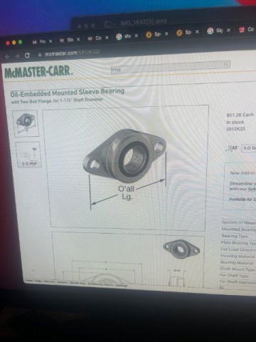
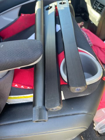
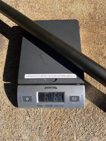
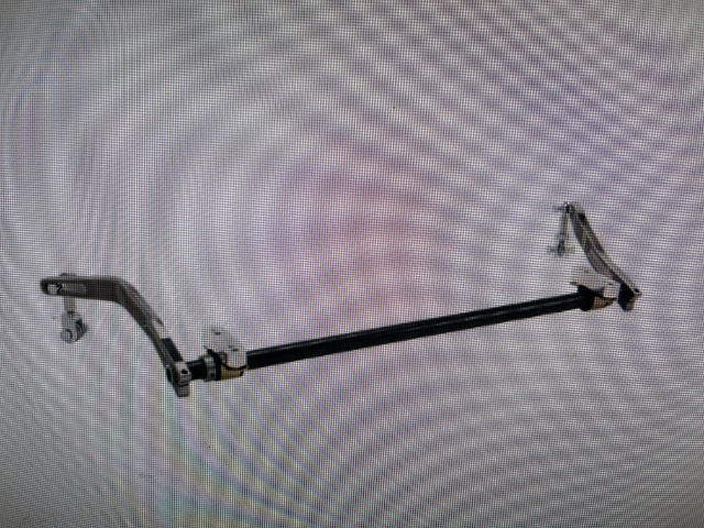
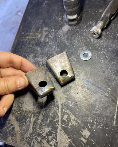
Okie dokie. I dived into the deep-end and got all the parts ordered for the sway bar As Clark suggested, speedway engineering bar. Got their alluminum arms too. They are local so picked them up today. Also ordered end links that will work with LCA attachment point and through-holes I need to drill into the AL bars. Also ordered two Alluminum housed bearings for the bar from McMaster-carr. Il take pics when I have it all mocked-up. Here are some pics of the parts I have and on order. i will fabricate the mounting of the bearing to the chassis. -
While we are on the topic, any suggestions on what this should look like for a non-vented rotor? We can now use cross drilled, but still stuck on the OEM calipers 😕 makes total sense that the centrifugal force will cause a vented rotor to flow air out the slots from inside the hat, but not very familiar with how to plumb to a solid rotor.
-
240z SCCA vintage race car, restoration
AydinZ71 replied to AydinZ71's topic in S30 Series - 240z, 260z, 280z
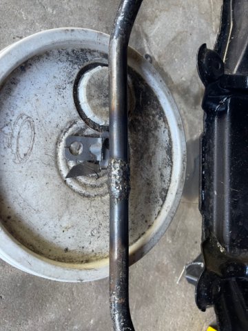
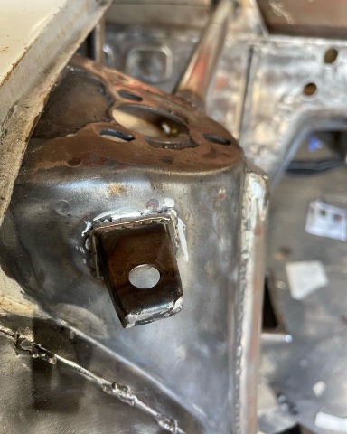
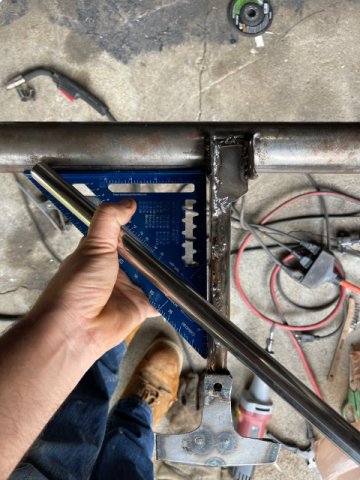
Thanks Clark! So I think I see all the parts I would need. I’m eyeing a 1-1/4” .188 wall 36”. I’m going for the aluminum arms. Now the OEM style bar “arm” has an angle (about 30 deg?) outward so the bar avoids the wheel/tire during steering. Any recommendations on how to bend the AL arm to accommodate as well? I suppose I could cal them Monday and ask if they can pre-band for me. meanwhile, I need to re-fabricate the OEM mount location to meet EP anyways, so I went ahead and lengthened the bar. I recognize the welded metal does not meet the stiffness of whatever alloy they used but now the bar makes it across so I can fab the chassis mounts. Just for shits and giggles, I did quench and hammer the weld so it’s harder than mild steel but I’m not going to use it anyways. It might just snap in half. I might want to see that. -
Unfortunately, if they are worth getting, they will be expensive minimum $1200. i would step Back for a second and identify your power/torque goals and budget. We could let you know the steps once that’s figured out. I have never boosted the OEM NA block, so I can’t tell you what the limit of the OEM pistons are. I have an L28et block where the OEM pistons were designed specifically for boost (rings are lower from the crown). The OEM bottom end should do 400ft-lbs of torque and whatever HP your head can flow. if you want something that is very reliable but staying under 400ft-lbs, I would just consider forged pistons designed specifically for boost. Beyond 400, you need better rods as well. Have not run into someone who broke the crank thus far (exception: poor balancing and machining). It’s way over-designed and heavy. with you head, have it CC’d. I doubt any of us have enough experience to know precisely how many CC’s you have left after removing 0.08 (which is a lot). Once you know the CC’s, it’s an easy calc to figure out your CR without a dish, and you can add dish CC’s to get the CR you need. i am oversimplifying since you also need to check your deck clearance, bore, etc. but that’s all easy the check yourself with a caliper. Then head CC’s are the thing most folks don’t have the patience and skill to do right, much machinists do it all the time.
-
240z SCCA vintage race car, restoration
AydinZ71 replied to AydinZ71's topic in S30 Series - 240z, 260z, 280z
ok guys... I totally underestimated the sway bar. Being a complete novice, i totally neglected this scope. So I am putting my front suspension on to mock-up the new chassis mounts for a sway bar. CLEARLY, my 1+" of front track is creating a problem getting on the OEM-style sway bar that came with the car (I am assuming it is the 1" MSA bar). The bar does not reach the wider spacing between the the control arm sway-bar attachment points. So, I have two choices right now: 1) Cut this bar, and weld-in 1" of material to make it longer 2) fabricate a new, custom sway bar I am certainly capable to do #2, but I do have some questions before I get started: 1) For those that fabricated their own, how did you handle the end-link connection between the sway-bar arm and the control arm? I am assuming a double-sided rod-end with shackles on the ends of the sway bar and control arm? 2) is there a clear performance advantage to the custom sway bar at this point? To be specific, do I need more torsional rigidity for a track car than the 1" bar can provide? My front springs are currently #350lb. thank you all in advance for your help!! -
IMSA GTU vintage racer build
AydinZ71 replied to clarkspeed's topic in S30 Series - 240z, 260z, 280z
Very cool! So if I am looking at it right, you have a tube welded to the frame with the sway bar rotating inside of it? I see long links I assume are intended to reach-down to the LCA’s. Also looks like it is mounted 4-6” below the elevation of the shock towers? Interesting! Excited to see it all come together! -
240z SCCA vintage race car, restoration
AydinZ71 replied to AydinZ71's topic in S30 Series - 240z, 260z, 280z
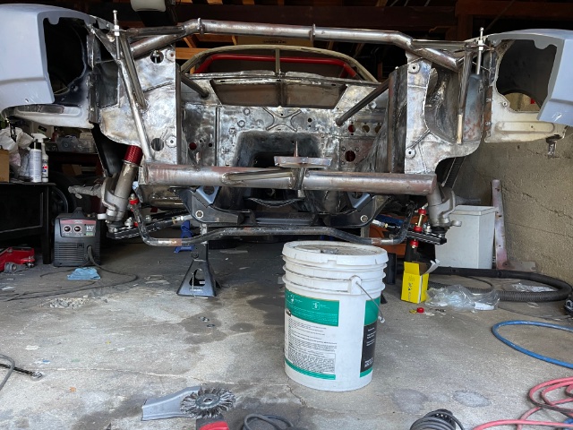
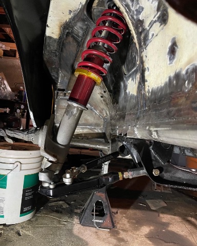
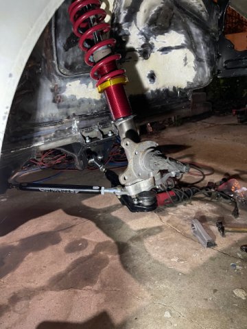
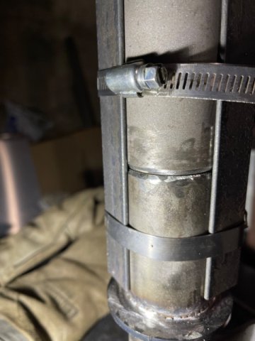
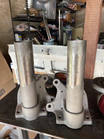
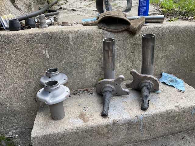
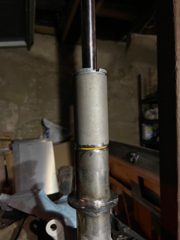
Thanks Clark! Smart to build-in some tie-down points. I’m super impatient, but I’m closing-in on finally being able to primer the bare steel. Everything you see mounted is just to ensure fitment before primer. Your chassis is more ambitious than mine so I can certainly understand the extra time you need. I need to fabricate the front sway bar mounts so finally got-around to sectioning the front struts. Got the whole suspension mounted (except the steering rack). Once the sway bar mounts are welded-in, I need to close some holes in the firewall and I should be ready to primer. IMG_7658.MOV -
fabrication of fresh air vent "piece"
AydinZ71 replied to Alexander240z's topic in S30 Series - 240z, 260z, 280z
Here is a tip on bending sheet metal: use a torch to warm it up (does not need to change color) and use a solid surface with a piece of structural steel on top to keep uniform pressure. Then just tap it with a hammer and she will bend i find the Datsun steel welds poorly. Combination of the cold gavlvonize coating they used, the impurities in the steel itself, and certainly the rust hidden between lap joints. IMG_7586.MOV -
240z SCCA vintage race car, restoration
AydinZ71 replied to AydinZ71's topic in S30 Series - 240z, 260z, 280z
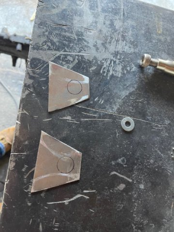
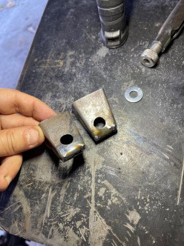
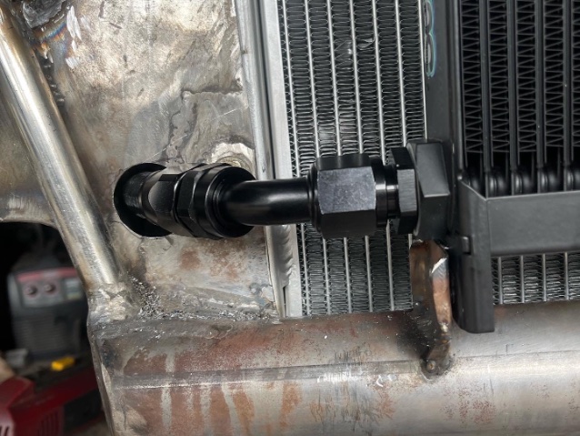
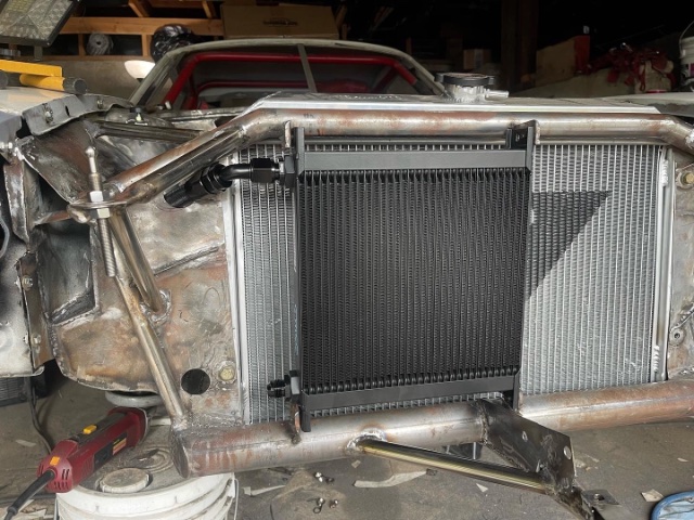
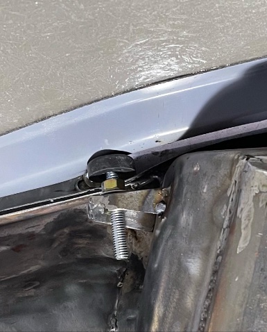
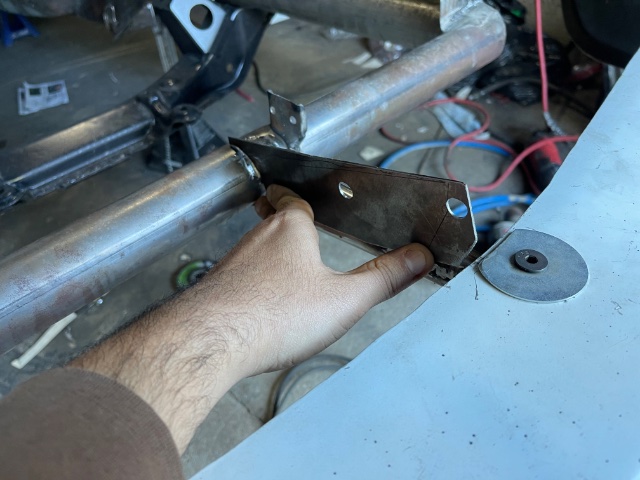
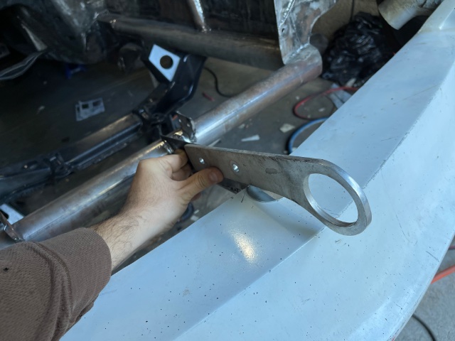
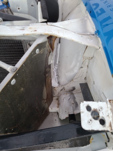
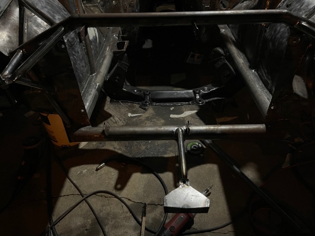
Updates: 1) tow-eye mount complete. 2) hood bump-stops installed on rad-side of strut towers. These can be replaced with quik-latch if the hood vibrates at speed. 3) pass-through holes in rad support for oil cooler lines. finishing touches before I can primer the front-end -
fabrication of fresh air vent "piece"
AydinZ71 replied to Alexander240z's topic in S30 Series - 240z, 260z, 280z
I hear ya I have been doing so much rust repair over the past year and a half that I feel more comfortable fabricating from scratch now than re-fitting OEM steel. Sounds silly I suppose. I did enjoy it after getting good at it, so I can’t say it makes complete sense. -
I agree. Some fasteners need a specific torque spec for performance (like the control arms or head bolts), but for most applications the standard torque spec for the diameter and grade of bolt is fine.
-
fabrication of fresh air vent "piece"
AydinZ71 replied to Alexander240z's topic in S30 Series - 240z, 260z, 280z
Looks good I fabricate replacement steel freehand as well -
240z SCCA vintage race car, restoration
AydinZ71 replied to AydinZ71's topic in S30 Series - 240z, 260z, 280z
Indeed! Thanks for the comment! I am curious to see how Much of this fiberglass is going to rattle at speed. started in the tow-eye today. Decided to go with just one, and might as well use the air-dam mount to save weight. Need to reinforce it a bit with a gusset or two and I’m done. Hope it fits under the fiberglass bumper in the future. -
240z SCCA vintage race car, restoration
AydinZ71 replied to AydinZ71's topic in S30 Series - 240z, 260z, 280z
Yeah I don't think the fiberglass one moves all that much, you are right about that. Still, I much experience driving 100+ mph in an S30. I calculate a completely flat surface would have 36lbs/square foot of force on it at 120mph. Kind of an extreme example, but if I push that hard on the fiberglass unit, it does definitely "plunge" without something fastening the leading edge. -
You know, I could be completely wrong on the venturi effect. Its just my opinion, but I don't have any data to support this. I have experienced this in mechanical lab, but never put any sensors etc. on a car. You said it, diffuser . I think the effect may be more complicated than I am giving it credit for. It actually is REDUCING the velocity by expanding the surface area with a consistent flowrate. If the velocity drops down to linear flow vs. turbulent flow, maybe that is the ticket? Anyhooo, I gladly concede
-
240z SCCA vintage race car, restoration
AydinZ71 replied to AydinZ71's topic in S30 Series - 240z, 260z, 280z
yep yep. That’s exactly what this is for fiberglass probably does a bit better on rigidity than ABS or Urethane (my street Z has a urethane one). I am allowed to fit a splitter from the leading-edge back to the front-most opening of the wheel well (so basically the whole width of the air-dam).That will keep the air-dam “nose” from “flattening”, but I needed this piece to apply pressure to the nose so all the force doesn’t land on the fenders/nose-cones. Also keeps the leading edge from “plowing” downward as you described. -
@madkaw oh I see! So the opening to the radiator is the only place air is going past the front fascia. Understood. Now I get what you are doing. You will be reducing the total size of the front-end orifice. If you do want to optimize for drag, you can still make the front-end opening narrower than the surface area of the radiator. It looks like the way you have it now has the orifice size matching the rad surface area which isn’t bad, you just don’t need it that big if you are trying to reduce drag. @calZ yes, going from a smaller opening expanding to a slightly larger surface area for the rad is a common strategy for minimizing drag but still getting good flow through the radiator. You see this on race cars, but also modern performance cars. Few that I have first hand experience on is a Z31 and Z32. The large opening we have on the front of an S30 creates more drag than the amount of opening we need for air to get to the rad etc. G-nose is one example of the front-end optimized. Any loss in airflow at lower speeds/stopped is made-up for with a fan on the back-side of the rad. these are all just generalizations, so I can share some photos and a pic from a book as examples if it helps.
-
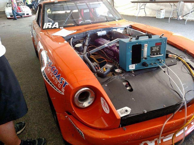
Just a tip from the Z-cars that race competitively: you want to block air from going anywhere other than the rad, oil cooler, fresh-air ducts (if you are still using them), and either an engine-air intake or allow cool air to blow through to the engine bay on the drivers side. From a weight management perspective, this means forcing the cladding you are proposing to the extremes. As in, take the concept of creating a front-facing shroud as you proposed but block ALL air from moving over (between the hood and the rad support), under (between lower rad support and your air dam/valance) and sides. the front orifice on an S30 is bigger than necessary so a lightweight bumper actually aids in aero by blocking and directing some air away from the orifice. attached is an example of Greg Ira’s car as an example. all this to say, your idea is not bad but not optimal (if you care). If you do insist on keeping it narrow, I would put a slight angle inward on the sides. Sounds counterintuitive, but this creates a Venturi effect at slower speeds which will actually increase velocity into your rad. Angling outward will cause an eddy current on the sides of the rad support creating drag. Keeping a neutral angle (as you drew) will cause a thin surface to “flap” due to turbulent air flow at speed. just some thoughts!
-
240z SCCA vintage race car, restoration
AydinZ71 replied to AydinZ71's topic in S30 Series - 240z, 260z, 280z
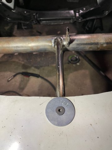
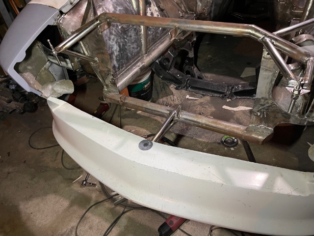
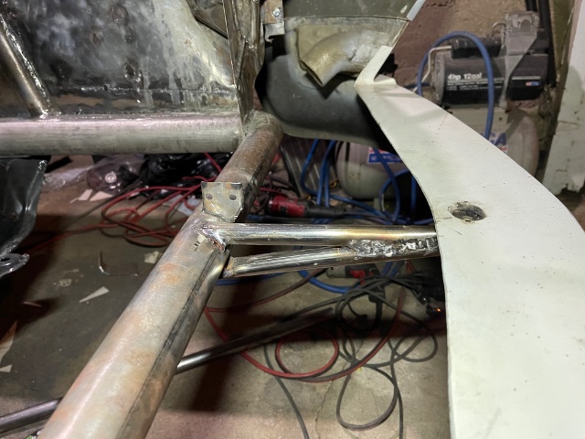
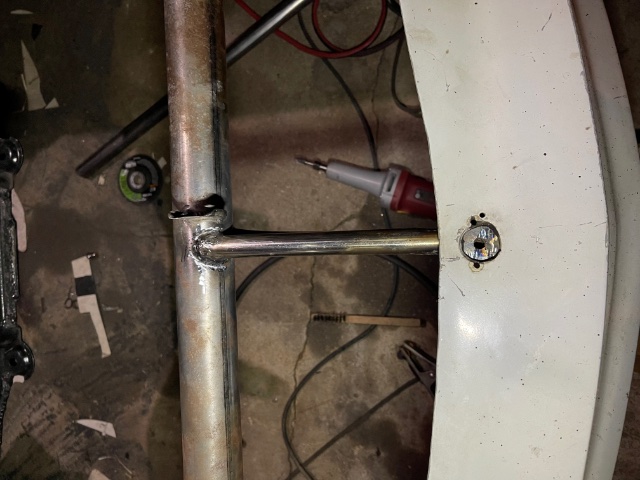
Added a support for the leading edge of the air dam, and a single fastener to keep the dam to resist torsion. Used the thin wall SS tube again so kept it pretty light -
ZCarDepot Fan Shroud and Mishimoto 12" Fan?
AydinZ71 replied to NorthStar's topic in S30 Series - 240z, 260z, 280z
Gosh, I never had any of these cooling issues. I wonder what is different… I have had either a clutched fan or a single 14” electric fan at some point on the L24 or the L28et, and in either case my temps in traffic never got much hotter than 200. Specifically, no shroud at all. Must be something fundamentally different about our driving styles. PS: the trans. cooler that comes integrated w/ the Mishimoto radiator is a sealed closed loop according to the manufacturer. I see you have caps on the nozzles, but I wouldn’t worry about coolant leaking out. I understand if you just want a prevent stuff from getting in there. -
ISOCYANATES! BAD BAD to breathe, this aserosol has it, read and heed
AydinZ71 replied to A to Z's topic in Body Kits & Paint
Sweet! You good good luck! -
ISOCYANATES! BAD BAD to breathe, this aserosol has it, read and heed
AydinZ71 replied to A to Z's topic in Body Kits & Paint
hmmm, is it OV/P100 or just P100? The P100 filters alone look like little saucers and are insufficient for organic volatiles. If it looks like a “canister”, 1.5” thick or so, then it’s the right filter. There is a little fold-out that comes with the canister describing the precise chemicals it protects against. if you can “smell” VOC’s, the respirator is not working. the regular p100 particulate filter is used for particulates (grinding) and vaporized metals from welding. I regularly switch between two masks, with the two different filter elements I need. -
yes, surge tank is cheap insurance by keeping a small amount (1pt-1-qt) of fuel in your engine bay, and allowing your fuel-pressure-regulator to dump back into this ready reservoir instead of sending all the way back to the tank. Short run for your high pressure line to suck fuel from, and push to your dispensers. Mount the pump under the surge tank. stock (carbureted fuel system) tank only has a single fuel line and no return. You need to tap the tank somewhere to run a new fuel line, and use the existing line for your return. Most people just replace the OEM fuel tank with a new fuel cell with multiple nozzles available. BOV is a blow-off valve. Most of the acronyms, you can Google. R180 is somewhat suspect at 300ft-lbs, but the weak spot are the spider gears. The LSD section replaces the spider gears so as long as the ring gear and output shaft bearings hold up, you will be OK. Double check with OS giken on whether the unit will handle the torque. That’s a super expensive part to risk blowing. HP vs. torque. If someone tells you HP is a reasonable metric to use for determining drivetrain strength, they don’t know what they are talking about. Torque breaks drivetrain components, and it’s what gives you that “whoa this car is fast” feeling in your ass when you stomp on the gas. HP depends on torque AND RPM (therefore a close correlation w/ volumetric air flow) and is used to determine things like air flow through a head, through a turbo, through an intercooler etc. When you quote an HP number but you really mean torque, someone is assuming a torque number off your HP number. They are variables in the same equation. for diff top-mount, search “techno versions 240z”. Read their product description. Lots of ports on this forum about it. I don’t know your personal finances, but il say this: if a shop does it all for you, they have to be “good” or your shit will fail often and be a headache. If they are good, they are expensive (thousands and thousands. Sung kang spent 250k on the fuguZ). Most of us here do it ourselves because we recognize we can barely afford the parts, let alone shop labor. We are also control freaks and want to understand why/how something happened and improve upon it, or we have serious trust issues. if all you need a shop for is to tune your equipment when done (and give free advice), that is affordable. O2 sensor screws into a bung downstream of your turbine outlet (exhaust). OEM L28et downpipe has one, so does the protuners downpipe. The wideband Meter uses the O2 sensor to determine how rich/lean your air-fuel ratio is. This lets you “rough” tune before you get to a performance dyno shop, and lets you troubleshoot while driving. Also helps to avoid running lean by accident if your equipment/fuel system fails. On-boost, 11:1 or richer is reasonable. Stochiometeic (sp?) is 14.7:1, but engines ALWAYS should run rich to a certain extent. NA will range a bit closer to stochio. if this is all a bit overwhelming, I understand. Take your time, read, do your research. If you decide it’s not for you, I get it. Just remember, you can not get a 250 whp L-series without a turbo, or losing a ton of street daily-driving capability on an NA. A 3.1L stroker will get you there, but driving on the street will be rough, and all your torque will be up-high (race engine). As an example, an all-out race engine L24 competing at the top of its class in SCCA puts out about 260 flywheel HP and that’s on race fuel. Maybe 10% more w/ triple carbs. these are not modern engines, but at the time they were a marvel.
-
If you are going for "easy" vs. "cost-effective", then you could just ask Hussein (Protuners owner) for everything he is willing to supply you. I know he sells injectors, ECU, etc. don't know about the rest. For pistons, you don't have to specifically ask for "recessed rings". That is a specific observation between the OEM L28et pistons vs. the OEM L24/L28 pistons. It is what Nissan did, and it made a difference on ring life. Just make sure they are clear on your displacement vs. power goals and that its a turbo application. They should have the experience to make the right piston for you. Most of the custom design work will be your electronics and fuel system. So, you should should sketch it out on paper until it all makes sense to you first. That way you don't buy parts you don't need and don't have missing parts. Here is an example of a robust fuel system design that will ensure high confidence you will not experience fuel starvation, regardless of HP (as long as the individual components are rated appropriately): Tank (modified for EFI, or brand new fuel cell) -> low pressure fuel pump -> fuel filter -> new 3/8" fuel line (OEM is pretty narrow and no return) to engine bay -> empty into surge tank -> HP fuel pump picks up from bottom of surge tank -> fuel rail/injectors -> FPR with return -> surge tank again -> surge tank overflow into OEM fuel line used as a "return" back to tank. You should confirm ALL of your driveline components will meet the 300ft-lbs flywheel torque. That includes the new CV shafts, driveshaft, trans, etc. Hubs i believe are OK to at least 400 ft-lbs, and Nissan 4/5spd should be OK to 350 ft-lbs as long as you are not "launching" at a drag strip. Do you own research though, plenty of posts and experience on this forum. Just run your CF clutch for now and maybe it will hold up? Not a catastrophic failure point, the clutch will just slip if its too much torque. You will need to convert to a top-mount or solid bottom-mount for your R200. The OEM rubber mount on the nose of the diff "pulls up" violently with lots of torque. Best-case your driveshaft U-joints will wear out pre-maturely. Worst-case, your diff mount will fail and the driveshaft will bind catastrophically, assuming your OEM diff over-strap is worn too (do 260z's have these?). do some research on a quality intercooler. You can piece together your own plumbing with pre-made mandrel bent 2.5" AL tube, straight lengths, and silicone of V-band joints. I prefer silicone of IC plumbing and V-band for exhaust. You need a BOV too, but get a "real" one. One that actually dumps some decent volume, not those little squeaky ricer ones. On turbo sizing, if you are going for garrett than use their online sizing calculator. Its free, and shows you precisely where your airflow demand is relative to the curve. The goal is to stay in the highest efficiency zone for as much of the airflow/RPM curve as possible. I think the best way to go from here is to prepare a complete and comprehensive list of parts, upgrades, tasks etc. We can review and fill-you-in on what we see is missing. Unless you are paying someone bookoo money to build it for you, you will need to understand as much of this as possible. You will have troubleshooting to deal with when its all put together and you will want to solve it yourself, if for nothing more than convenience. I don't have direct experience on a before-after on the cooling system mod, but the idea is to get the coolest water back to the last two cylinders. When done correctly, it can not hurt and will only help. the cooler the water jacket, the cooler the cylinder walls, the longer your rings will last, and the higher your detonation threshold will be.
