NewZed
-
Posts
6700 -
Joined
-
Last visited
-
Days Won
72
Content Type
Profiles
Forums
Blogs
Events
Gallery
Downloads
Store
Everything posted by NewZed
-
They all should have backed in (coincidentally, related to how I failed a forklift driver job interview test, many years ago) - Car #4 is a Z.
-
Looks like there might be one in Salt Lake City - http://www.picknpull.com/check_inventory.aspx?Address=97225&Lat=45.506451&Lng=-122.775622&Make=Datsun&Model=280&Distance=25000 If the link doesn't work just go to the Pick n Pull site and check inventory - http://www.picknpull.com/default.aspx
-
Have you checked timing? If it runs, then coil and module are probably doing their jobs. If you put the second pickup in its original spot, the timing wil be off. And what do you mean by "not well"? Could mean almost anything. The first module might have died due to poor grounding. They need a good solid ground for the coil current. Your sheet metal screw in to the fender may not be good enough. I'm not a transistor or ignition expert, but these are the basics for the GM HEI module. Pretty sure that the pickups are identical.
-
Early 260z L28et swap wiring issues
NewZed replied to TheBlaiant's topic in S30 Series - 240z, 260z, 280z
There's only 25 pins used at the ECCS connector. The purpose of each is shown in the FSM. A little time with an ohm-meter and you'd probably have it figured out. Just saying'. Always good to double-check anyway. Plus you can test the components on the ends of the wires at the same time. -
A 77-78 body probably requires a cat and EGR. 75 most likely has neither. Just an observation.
-
Congrats. Hard to believe after the long trail. It's always the little things that get you. Now that it's working right, you should probably make sure that the vacuum advance breaker plate isn't rusted frozen, just to get full benefits. The vacuum advance can will eventually break the plastic bearing holder if it's stuck too hard. Might have to take it apart, remove some rust and relube it. And don't forget to open up the gap on your plugs to take advantage of the stronger spark. .040" is about the common standard for electronic ignition.
-
Why don't you post the negative comments or links to the threads so people know where you're coming from? Sounds interesting, I wouldn't mind knowing more myself.
-
I think he's talking about the plastic nozzle on the end of the air intake tract. On the 280Zs at least, maybe the 240s and 260s, they bent the intake back in to the engine bay, so the air is drawn from the engine side of the radiator mounting "wall", right in front of the charcoal emissions canister. I have one on my 76. It's attached with a band clamp to the typical Z car metal air filter housing. Probably designed to keep water and debris from getting in. It could be debatable on whether or not the air is warm. You'd have to know how the air flows through the engine bay. But yes, it is the entry point of the air intake system.
-
Set the gap between reluctor wheel and pickup coil according to the FSM, Electrical section. It's important. An easy adjustment. Maybe the triggering voltage is too weak for a few of the reluctor wheel teeth.
-
At least the coil and module are working. Did you buy a 1975 cap or a 1973 cap? Apparently, according to the O'Reilly Auto web site, they're not the same. I don't know how they're different, just that they sell two different parts for those years. You need a 1975 cap. Probably a 75 rotor too. Click on the Compatibility tab - http://www.oreillyauto.com/site/c/detail/IDI1/100121/02783.oap?year=1975&make=Nissan&model=280Z&vi=1209204&ck=Search_distributor+cap+%26+rotor_1209204_-1&keyword=distributor+cap+%26+rotor Almost there.
-
The second pickup works separately from the first one. It's just 6 degrees advanced. It would have been controlled by the stock ignition module. Since you've measure 717 ohms at the wire, that pickup coil looks good, most likely, you don't want them in-line. You get spark from coil negative, which is the coil primary charging up, but do you get spark from the main spark distribution wire that feeds that distributor cap? You should get a spark at both. I haven't seen a picture with the main coil wire connected. And did you disconnect the second wire from coil negative like Six Shooter suggested? The circuit from the coil negative to ground has to be broken or the coil will not discharge through the main center terminal. W and G just take the tiny pulse from the pickup coil and use it to make and break the circuit from the coil negative wire to ground.
-
That's a good point. ON a 280Z that might be the wire to the tach and ECU. On a 240 it might be keeping the coil primary circuit closed, stopping the coil from discharging.
-
You might try a dedicated ground wire from the mounting hole to a good ground on the block. The fender that your sheet metal screws are attached to might not have a good ground. Otherwise, everything looks good. Here's something to look at, that I've done before - did you remember to put the rotor on top of the distributor shaft? So the spark can get from the main coil wire to the plugs? You've shown that all the pieces are good, maybe it's just a bad connection between the coil output and the plugs.
-
Your numbers here and in Post #7 look right. It should be sparking. If the G and W leads were backwards you should still get spark, as I understand it, but the timing would be erratic. It won't hurt anything to swap the G and W leads and try it. Maybe there's a reason that distributor was free. The resistance across the pickup coil leads (disconnected from the module) should be ~720 ohms according to the FSM. Edit - to add a little to Six Shooter's - you could also measure the voltage across the distributor pickup coil leads as you spin the distributor (it can be hard to see though with a digital meter). It should rise and fall as the star-shaped reluctor tips pass the pickup coil. You didn't mess with the pickup coil did you? It needs a certain clearance to work right.
-
Have you checked for power at the coil? Battery voltage on both sides with the key on? Did you ground the HEI module to the aluminum plate and the plate to the body (back to battery negative)? The mounting holes in the module are the electrical ground circuit for the module, the mount is more than just a heat sink. A little work with a volt/ohm-meter might clear things up. Here's another link with the original link to the one I posted inside. Go down to "Index of Technical Articles, then to Engine - Ignition system, 280Z/GM HEI Module for your 240Z, then inside that article you'll find "Here's the source..." with more details on how to troubleshoot the new parts. Sorry I can't just post a direct link, it's an odd web site format. http://zhome.com/ It shouldn't be too difficult,if you break it down in to the basics. For example, if the coil has power, you can test for spark by tapping a jumper to ground from the coil negative. That's what the module does, makes and breaks the coil circuit. If you don't get a spark that way, the module won't give one either.
-
Cylinder head temperature sensor (CHTS) maybe. Bad connection or faulty. See EF-26 in the FSM. www.xenons130.com/reference
-
The flywheel that I used with those parts measured a hair over 7/8" from the surface that touches the crankshaft to the pressure plate mounting surface. So the distance from the crankshaft mounting surface to the two surfaces of the ears on the collar that touch the fork would be 3 1/2 plus 7/8" or 4 3/8". From crankshaft through the stack of flywheel, pressure plate and collar to where the collar contacts the fork. The flywheel thickness itself was 1" from back to front. It came on a 1976 280Z L28 and I wouldn't be surprised if it was the original. Good luck with it, I'm sure there's leeway in the range possible that will work. I'm interested in the measurement you end up at, just for the record.
-
Not positive but I think that's the BCDD solenoid. There's probably a hole up under the throttle body where that used to be. And the ground wire connector in your other picture actually came from the condenser/capacitor up by the coil. The BCDD solenoid actually has its own power supply through the harness up to a gismo (amplifier?) connected to the speedometer, I believe. It's described in the Emissions section of the FSM.
-
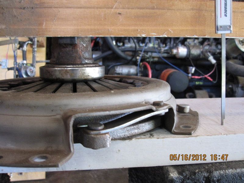
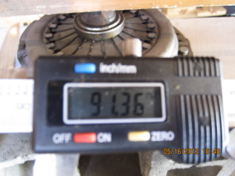
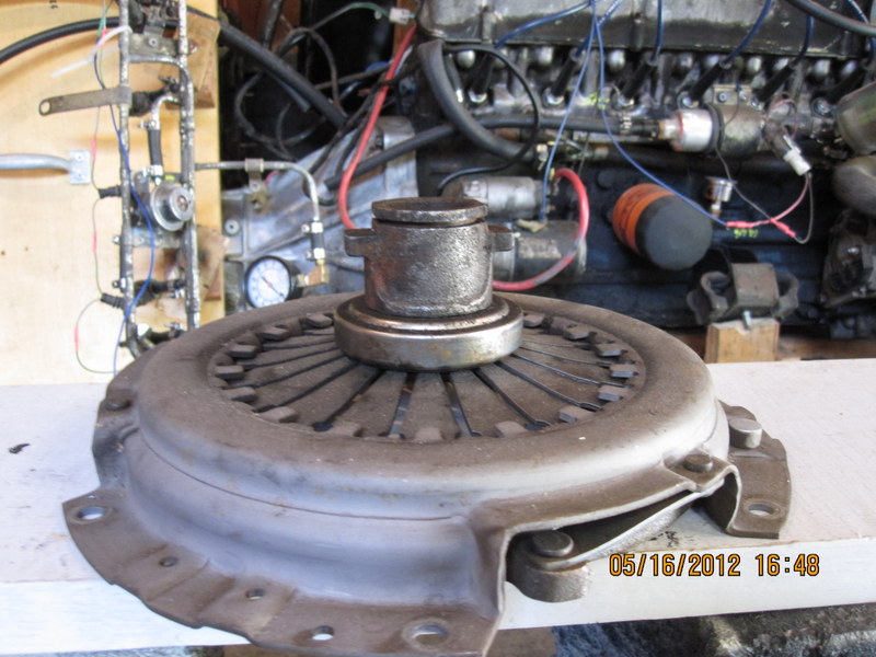
This comes up all the time and I just realized that I have the pieces in the garage to take the critical measurement. Assuming that the slave cylinder is the same distance from the back of the block and the flywheel thicknesses are the same, and the clutch forks are the same, then the distance from the bottom of the pressure plate to the surface that fork sits on is the distance that needs to be within a certain range. The pressure plate and the collar are the two things that vary over all of the combinations. So here's a few pictures of a pressure plate with a long collar, a combination that I used to have on my car. The pressure plate is the one I used, the collar is not, bit it's identical to the one that was used with that PP. The distance is 90 mm, or 3.5 inches, from the surface of the flywheel to the surface the clutch fork rides on. If I was starting from scratch with unknown parts, that's the distance I would shoot for. Edit - the caliper measurement looks off in the picture due to camera angle.

-
Thanks. Interesting. That's a tight fit.
-
The "How to Modify" book says to never get less than .050" clearance between piston and head, .055" in a race engine. .030" is asking for problems isn't it?
-
Here's a link that shows the hole with the adjustment screw. The screw is kind of deep inside, with a big slot, hard to reach depending on the orientation of the AFM. Often they're factory sealed with hard clear plastic that you'll need to break loose, sometimes just a rubber plug. Keep track of how many turns you use in case you want to go back. Don't get carried away with all of the other advice in the link if you're just trying to lean out your idle. The first color picture - idle "flow" adjuster. Out is leaner, it lets more air past the AFM vane. http://atlanticz.ca/zclub/techtips/afm/index.html Edit - it's possible that the turbo AFM doesn't have this, I haven't actually worked with a turbo AFM.
-
The hold at 2,500 is just a second chance to pass if you fail initially. They don't measure. So the AFM idle air screw leaning should get you there, assuming you don't have any missing from bad plugs, wires, etc. I'm surprised they tested without the converter, unless they were just giving you some numbers to work with. The door jam tag tells if your supposed to have one and I don't think that they'll pass you without it.
-
Turn the AFM idle air screw out as far as you can before getting a lean miss, then turn it back in a half turn. I don't know what tests they run for an 82 but they only test idle for 1976.
-
Possible vapor lock issue? (Carb'd 240z)
NewZed replied to BrandenZ's topic in S30 Series - 240z, 260z, 280z
Isn't this why Nissan added the electric pump?