Miles
-
Posts
2393 -
Joined
-
Last visited
-
Days Won
37
Content Type
Profiles
Forums
Blogs
Events
Gallery
Downloads
Store
Everything posted by Miles
-
 http://www.classiczcars.com/forums/topic/47304-1972-float-adjustment/
 -
WIth stock brakes, a 1 in. MC is expected to make the pedal hard to push. Replace the 1 in. MC with the stock 7/8 in. MC and your brakes will be fine.
-
1. Download a Factory Service Manual (FSM). Should be available several places at HybridZ. It explains how to work on a Z car. 2. Follow the instructions in the FSM http://www.nicoclub.com/archives/2-write-ups-on-tuning-su-carbs.html This video is for British SU carbs, but basically the same procedure. Also, make sure that the needle moves freely in the seat as you move the float up and down.
-
https://www.youtube.com/watch?v=y059hdXvVwg https://www.youtube.com/watch?v=SLD_7pNRfbk https://www.youtube.com/watch?v=JOIFJEO7mTM https://www.youtube.com/watch?v=7GRAcqDySog https://www.youtube.com/watch?v=60Bj_2cZQnc
-

-
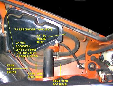
Note that the tank has a bulge on top. When the tank is filled air becomes trapped in that bulge if there is no way for it to escape. If the air can't escape then the gas tank will not be able to be filled all the way. Think of inverting a glass and submerging it in a sink filled with water. The air stays trapped in the glass. Also note that gasoline expands when it gets hot in the summer. In the early 70s the US required that automakers had to capture hydrocarbon fumes/vapors escaping the fuel system. The tank and all of those hoses make up a vapor recovery system. The purpose of the vapor tank and those hoses was to capture the fumes and pass them through a carbon filter and suck them back into the engine to be burned (see your FSM). It also serves as a vapor expansion tank. It is designed as a closed system. The stock gas cap is not vented. The vapor tank collects gas vapor and serves as an expansion tank. As the gas in the tank expands it pushes the fumes/air into the vapor tank. So the reason you connect hose 8 to the filler pipe is so air trapped in the top bulge has somewhere to go as the tank is filled and/or gets pushed out by expanding gas on a hot day. I used fuel injection hose to connect the tank bulge to the filler pipe. So when filling the tank or gas expands on a hot day where will that air go when the vapor tanks is removed? The air wiil escape through a 1/16in to 3/32in drill hole ("breather hole") you make in the gas cap. Do not top off your tank after removing the hoses and the vapor tank because on a hot day gas will expand and will be pushed up into the filler pipe and escape around the gas cap and through the small "breather" hole. Just fill until the hose shuts off. Note that the vacuum switch on the inner fender probably is corroded and plugged up. Every one of those I inspected was completely plugged. If you do remove the hoses, you will have to weld or braze all of the tubes on the gas tank closed. Do not just plug the tubes. Think collision. Of course if you plan on getting the engine swap certified by the California DMV you can't make any of these changes. Recommend that you search the forums for more information before you do any modifications. There are many many posts on this exact subject.
-
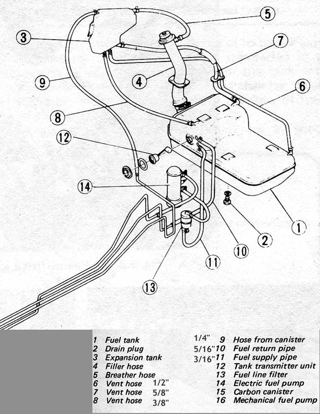
What year Z would help. You will need to keep line 8 or line 7 and route it to where line 5 attaches to the filler neck in the picture below. Look at the picture and you will see why you need to keep the line in addition to venting the tank on hot days.
-
Headlight relay harness built by a HybridZ member (HLS30-08077) and sold by MSA: http://www.thezstore.com/page/TZS/PROD/12-4651 Or buy direct from Dave (HLS30-08077): https://www.datsun-240z-upgrades.net/product-info/ Works!
-
1. What year is your Z? 2. Did you check the fuse panel? 3. Typically, the problem you have is caused by the turn signal and/or the light switch. Many "how to" posts on switch repair here and on the internet. 4. Information: http://woodworkerb.com/home/datsun-240z-rebuild/datsun-240z-multifunction-switches/ https://www.datsun-240z-upgrades.net/services/ https://fiddlingwithzcars.wordpress.com/2012/12/04/turn-signal-repair/ http://www.classiczcars.com/forums/topic/34330-72-240z-turn-signal-stoped-workining/ Rebuild_240Z_combo_switch.pdf
-
Last weekend I got some needles and the complete bottom seat assemly off a 72 240 that was completely rusted in rotted out including the carbs or at least they looked pretty beat. I have yet to take my carbs out and swap the needles and seats but at least now I have something to try. And now you got me thinking about the Pistons. Google search results: https://www.google.com/search?biw=1536&bih=741&ei=GB5lWof6K8LYjwPRqZmACg&q=240z+su+carb+lean+backfire&oq=240z+su+carb+lean+backfire&gs_l=psy-ab.12...48161.51822.0.54621.8.8.0.0.0.0.107.703.7j1.8.0....0...1c.1.64.psy-ab..0.6.545...33i21k1j33i160k1.0.TrwnWHR2y0U
-
5 Speed Transmission goes into gears, but is always in neutral.
Miles replied to supershanesta's topic in Drivetrain
Possible mismatch of clutch parts e.g., 240z - 280Z throughout bearing components. Do a Google search or HybridZ and search for 280Z transmission swaps. Also, this issue has come up before so there should be some info here or at one of the other Z blogs. Check the FSM for a 240Z and 280Z transmission. -
With the engine off, place firm pressure on the brake pedal and hold that pressure. While holding pressure on the brake pedal start the car and post what your foot does.
-
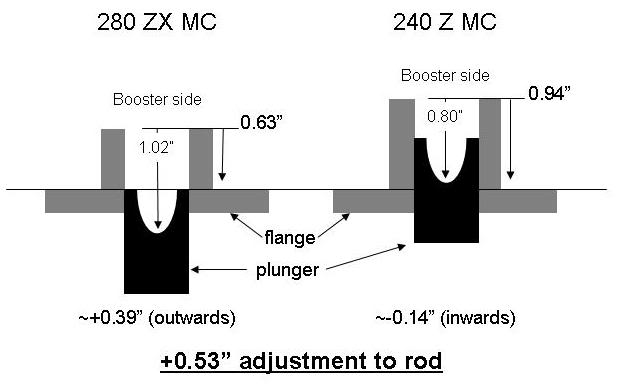
The mounting hole pattern on the 240Z and 280Z are different. The horizontal spacing of the mounting studs is wider for the 280Z so I had to re-drill the mounting holes in the fire wall. It has been eight years since I was working this issue, but I recall the that the 280Z and 280ZX bolt spacing is the same. If you have a 76 280Z then your booster is most likely 8.5 inch diameter. And you should already have an 8.5 inch booster installed. Time to measure the booster you have and also measure the space between the throttle bracket and the clutch slave. That will determine what diameter booster you can use. If you have an automatic z then the clutch slave is no factor and you could install the 10 inch 280ZX booster.
-
The 75 - 78 280Z came with a 8.5 inch booster which is what I am using on my 72 240Z with 15/16 inch. The larger 8.5 inch 280Z booster made the pedal less stiff. I would like to have used the larger 10 inch 280ZX booster, but there was no room between the throttle bracket and the clutch slave. See pictures. The space between the throttle bracket and the clutch slave is the limiting factor. The 280Z has more space between the throttle bracket and the clutch slave so a 79 280ZX booster might fit. I recall that the 280ZX booster is 10 inch diameter. The 80 -83 280ZX booster uses a horizontal MC mounting flange whereas the 240Z, 280Z and 1979 280ZX use a vertical mounting flange. I had many Hybridz links on booster swaps, but the links are now dead. Note that there were changes in mounting bolt patterns and the clevis that connects to the clutch pedal. I swapped the push rod and clevis from the 72 booster to the 280Z booster so everything matched.
-
72' Distribution Valve
Miles replied to M_Motorsports's topic in Brakes, Wheels, Suspension and Chassis
1. Set all of the mechanical brake adjustments, including the push rod, correctly. See push rod length adjustment above. You can do fine adjustment to the rod after the car is safe to put on the road without removing the MC. 2. Bench bleed the MC. Take your time and get all of the fine bubbles out. Make sure none of the fittings or plastic lines are sucking air. Transfer the MC to the car with the outlets plugged. Attach MC to brake lines loosely and then to the booster. Tighten the brake line fittings after the MC is attached to the booster. 3. Bleed brakes with a helper or use speed bleeders (check-valve style) or use a Motiv pump bleeder (what I use). The pump bleeder works well, but can be messy. On some calipers you have to remove the caliper, block the pistons, and shake/rotate the caliper while bleeding to get the air out. Be sure to block the pistons. If you don't block the pistons you will be very sad. -
72' Distribution Valve
Miles replied to M_Motorsports's topic in Brakes, Wheels, Suspension and Chassis
The piston needs to go full stroke. -
72' Distribution Valve
Miles replied to M_Motorsports's topic in Brakes, Wheels, Suspension and Chassis
Did you bench bleed the MC? -
72' Distribution Valve
Miles replied to M_Motorsports's topic in Brakes, Wheels, Suspension and Chassis
When bleeding calipers make sure that the bleeder is pointing up and not at an angle to get all of the air out. -
72' Distribution Valve
Miles replied to M_Motorsports's topic in Brakes, Wheels, Suspension and Chassis
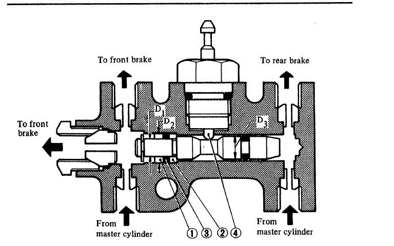
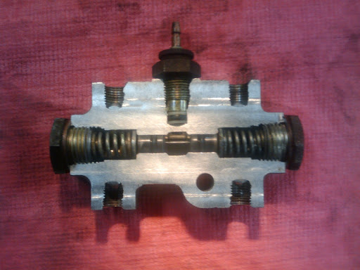
The device under the MC is called a "differential pressure switch". In the event of front or rear pressure loss, it shuts off fluid going to the circuit that has the lowest pressure i.e, a leak. It also serves as the distribution block for the front and rear brake lines. When a leak occurs a shuttle inside the valve moves to the lower pressure side of the switch to stop fluid flow and the shuttle touches an electrical contact that turns a red light light on your dash. That is it. Leave it alone. See pictures. The calipers you installed require more fluid hence the longer pedal. If you have to pump the brakes then you still have air in the system. Recheck all of the mechanical linkage adjustments including the MC push rod and re-bleed the brakes.
-
Are you over thinking the problem? Research the function of a thermostat. I see you are in the Bay area where it tends to be cool. You haven't mentioned what the air temperature is when the water temp appears too cold. What are the temps on a 90 - 100 deg day? Perhaps you need to calibrate your temp gauge and sender by measuring actual water temperature with a digital thermometer (meat thermometer works). Place the probe between the fins close to where the return hose connects to the radiator. Could be that you just have an efficient cooling system!
-
Was there a typical size for sunroofs? Mine blew off
Miles replied to dpuma8's topic in Body Kits & Paint
Had similar problem on my first 240Z. I just took it to a "sun/moon roof shop and they matched the existing unit. Or you can measure the hole and research a replacement on-line. -
http://www.kamikazeracing.org/dl/ZTech/Rebuild_240Z_combo_switch.pdf
-
Wilwood Prop Valve Adapters
Miles replied to KevvinG's topic in Brakes, Wheels, Suspension and Chassis
Boy I don't know what Wilwood's problem is with making 10mm x 1.0 inverted flare adapters. A lot of Japanese cars use inverted flares. -
Wilwood Prop Valve Adapters
Miles replied to KevvinG's topic in Brakes, Wheels, Suspension and Chassis
I looked at this a long time ago. It is 10mm x 1.0 bubble flare. From Summit: Q: Is it an inverted flare or bubble flare on inlet and outlet? Asked by KENNETH on June 02, 2016 A: Thank you for your question. Wilwood Disc Brakes 260-12627 would have a 10 mm. x 1.0 bubble flare on both inlet and outlet. In 09 I checked with Wilwood. They had no interest in supplying 10mm x 1.0 inverted flare adapters or a PV with those specifications.