jonbill
-
Posts
186 -
Joined
-
Last visited
-
Days Won
1
Content Type
Profiles
Forums
Blogs
Events
Gallery
Downloads
Store
Everything posted by jonbill
-
Kameari - anyone using their pistons and rods?
jonbill replied to AydinZ71's topic in Nissan L6 Forum
Forged street pistons, 88.5 & 38.1 PH and 89.5 & 35.5 PH. -
Kameari - anyone using their pistons and rods?
jonbill replied to AydinZ71's topic in Nissan L6 Forum
I just emailed Mr Mori. or is it Mr Kame? I'm not sure, but he's very helpful. kame.mori@nifty.com -
Kameari - anyone using their pistons and rods?
jonbill replied to AydinZ71's topic in Nissan L6 Forum
I have Kameari pistons in two engines. (w/ maxpeedingrods rods). Never had any problems and Kameari are really good to deal with direct. -
seems to be a fairly common problem with Safari on ios. Is that what you're using @calZ?
-
Is it possible to bore a l24 to fit 89mm pistons
jonbill replied to Estoque grigio's topic in Nissan L6 Forum
I think accepted wisdom is that p30 block can be safely taken to 86. n42/f54 blocks preferred for bigger bores. unless you're prepared to fit liners of course. -
It doesn't matter I know, but I'm compelled to point out it is torsen (torque-sensing), not torsion or torsten. Sorry.
-
are there sparks and do the plugs get wet with fuel?
-
2021 l28et connecting rod questions, OEM limits, Forged options, etc
jonbill replied to Sideways's topic in Nissan L6 Forum
I have rods from Maxspeeding rods in my current and previous engine. I have very close tolerances between piston and head and no contact and no problems at all. I'd recommend them. -
I think a short stroke engine is cool, but even the LD crankshaft isn't super long stroke and will rev. I'm revving mine to 7700, and my previous engine with l28 crank went well past 8. (in the end it was valve train that limited the rpm)
-
Thanks. I like the weather TBH. Brexit is... hard to explain This pic is of the piston in situ - you can see where the proximity of the head squish area has kept the piston clean. This is my previous engine with 0.6mm head to piston clearance.

-
my gearbox makes noises like that.
-
I've got 11.8:1 on normal fuel, but I believe our fuel is better in UK than yours. I run it on 99 ron, although I didn't hear any pinging on 95 either. 0.8mm clearance and lots of squish.
-
you've either been incredibly unlucky or its not the diff. anything unusual about the suspension or gearbox setup? whats the noise like coasting out of gear? in gear with the clutch in?
-
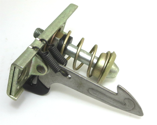
This thing. It can be screwed in and out a bit to adjust height. (photo borrowed from jdmcarparts.com)
-
if you can get it low enough at the front but its too high at the bulkhead, the height can be adjusted by screwing in the catch bolt in the bonnet. if that doesnt make any difference, check if the bonnet is resting on the rad core support at the front. if it is, you'll have to take the bumper off z loosen all the wing bolts and raise it a bit and start again.
-
Trouble on initial starting..please help
jonbill replied to jersey280's topic in S30 Series - 240z, 260z, 280z
cold start isn't what happens when its cold outside and you start your car. ANY outside temperature is a lot colder than the running temperature of the engine, and it needs fuel and timing adjustments while it warms up. so suspect a temp sensor somewhere. -
Anyone have experience running E3 spark plugs?
jonbill replied to Mike33Stig's topic in S30 Series - 240z, 260z, 280z
I don't think you're engine is running lean. -
Yes, just lowered. Its a diesel block, 20mm taller, and I wanted it to still fit under my strut brace.
-
Fwiw, I lowered my engine 20mm and had to grind a little off the oil pan edge and rack mount. so 2" lowering would need some work.
-
I think the LD28 oil pump is the same as the NA petrol oil pump. the LD28 water pump is higher capacity than NA petrol and the petrol Turbo oil pump is higher capacity than NA petrol. you can buy the Hitachi turbo zx oil pump from rockauto.
-
the hose is probably for the MAP sensor in the MS. it measures the air pressure in the manifold. (high with the throttle shut , low with it wide open). It needs to connect to the inlet manifold between throttle and engine. the place you bought it must have some instructions.
-
The diagram shows the injectors have +12v at all times I think; doesn't go through the switch. So: it will idle on 5, but if you try to rev it higher, it dies. correct? But, if you ground the 6th,through your test light, it will rev. correct? as @NewZed said, its probably bad earths from the ECU.
-
so it runs with any 5 of 6 injectors plugged in and any 1 of 6 disconnected? or is it a specific one that has to be disconnected?
-
The epoxy putty fell off during the run in, but it didn't leak 🙃 I've put another lump on now, mainly for luck!
-
.JPG.6dace6892aadfedf3ff6346a168b9d4b.JPG)