Chickenman
-
Posts
1052 -
Joined
-
Last visited
-
Days Won
9
Content Type
Profiles
Forums
Blogs
Events
Gallery
Downloads
Store
Everything posted by Chickenman
-
Dyno'd my stock L28ET today - coolant everywhere!
Chickenman replied to AlbatrossCafe's topic in Nissan L6 Forum
That's usually a voltage offset problem or Calibration problem in Tuner Studio. Hussein gives direction above to correct that. However, I wonder if there is a connection between the two. You mention that your engine has been running a bit rough lately. Then I saw low alternator levels in TS. Then we have the AFR gauge and TS reporting different values. I wonder if you have a bad or loose ground somewhere? That could cause all three symptoms. -
Dyno'd my stock L28ET today - coolant everywhere!
Chickenman replied to AlbatrossCafe's topic in Nissan L6 Forum
14Point 7 will show you error codes on the WB controller. What makes your think it's failing Steve. -
Steve. I'm working on finding a better Injector battery correction curve for your injectors. The default setting is way off. Unfortunately your injectors are proving hard to find the DT voltage correction tables. I may have to use something close. In the meantime, can you send me your Current Tune. Or the last one that was working properly? I don't have your current version on file. Could be something entirely unrelated as well. Just as a hunch. Reflash your firmware with a newly downloaded version. Be sure to save the old Project. I've had some experiences with the Firmware on MS getting somehow corrupted. This has happened to a couple of cars. Does some very strange things. Back from Vacation now... Richard
-
Dyno'd my stock L28ET today - coolant everywhere!
Chickenman replied to AlbatrossCafe's topic in Nissan L6 Forum
Biggest problem with Innovate and why it kills O2 sensors is that " apparently " if it detects any Error message, even a temporary one. it shuts down the heater circuit. Until the next restart. That will kill O2 sensors in a real hurry. Other WB controllers including OEM don't do that. You log the error message( Contamination, out of range or aging ) you don't shut down the whole heater circuit. -
Dyno'd my stock L28ET today - coolant everywhere!
Chickenman replied to AlbatrossCafe's topic in Nissan L6 Forum
Individual COP is nice, because you can do spark timing trim per cylinder. #5 and #6 running a bit hot? You can trim them back a degree or two individually. Very nice feature. -
Dyno'd my stock L28ET today - coolant everywhere!
Chickenman replied to AlbatrossCafe's topic in Nissan L6 Forum
" Moby The Van " article is getting pretty dated theses days. You are better off following the MS Extra Hardware manual and using either a BIP373 for a Ignition driver or a PRW2. Bip 373 is a whole $8.50. PRW2 can be found for as little as $10 to $15. A lot of changes and improvements in Builds and Firmware since that article was written. -
Dyno'd my stock L28ET today - coolant everywhere!
Chickenman replied to AlbatrossCafe's topic in Nissan L6 Forum
Yep. 14point7 = good stuff. Just stay far, far away from Innovate. POS. OEM O2 sensor is Narrow Band. You need a Wide band. -
You have to take Motor Trend Engine Masters with a big grain of salt. They are Drag racing oriented and only tend to concentrate on overall HP figures. For Road Racing , Auto cross or even general street driving, some of their videos are full of omitted data. Lots of holes in their testing parameters in some cases. Their test of Mechanical vs Electric Cooling fans was a complete joke as they never tested the most important aspect of cooling fans. CFM. Also, the mechanical fan they tested was an old design. With heavy metal blades and low efficiency blade design. It was a full lockup design, not a governed RPM design likie Nissan uses and not high efficiency, curved 7 and 8 blade designs with lightweight Plastic Blades . Again Drag Racer oriented and Detroit specific.
-
It's not a bad video . I recently just did the same mod on my N47 head. Engine has 10.3 to 1 CR and is a bit detonation sensitive on the two back cylinders. We have crap fuel where I live. I only did cylinders #5 and #6. Don't feel there is any need for more on a street driver. Also, front hose is way too large. 3/8" hose or 5/16" hose is all that is required. You just want to get rid of steam pockets near #5 and #6 and provide a bit more balanced flow. I used the Fast fuel rail. It has an 11/16" ID. That makes the walls rather thin if you thread them for a NPT fitting. Instead , I got some 11/16" core plugs. Used Loctite pipe sealant on them and tapped them into place. Tapping the end of the FAST rail for NPT thread would leave the wall so thin, I would be afraid of cracking the rail. If you got a different brand fuel rail with only a 1/2" or 9/16" ID, that would be better for tapping the ends. I don't know why FAST made the ID so large. Most other rails are only 1/2" to 9/16" ID. That leaves enough meat at the end of the rail to Tap for a fitting. Edit: Instead of tapping the end of the Fuel rail for the brass NPT fitting I plugged it. Then , I used a 90 degree 1/4" NPT brass fitting with a 3/8" hose nipple to connect to the thermostat housing. Tapped the bottom side of the rail with a 1/4" NPT for the return fitting. Same as the tapped holes for the fitting's for the cylinders. I retapped my Thermostat housing from BPT to 1/4" NPT. Really, that's only a minor thread clean up.
-
2.5" is more than enough for any NA L28 engine on the street. Even on a stroker. You will see minimal gains in HP between a 2.5" exhaust and 3.0" on a NA engine. Much more important on a Turbo engine. What you will see ( or hear ) is a LOT more exhaust drone and noise from a 3" system. FWIW. I ran a 425HP Camaro Hillclimb car on a single 3" system. Under chassis design on Third Gens limited exhaust choices. The minor amount we lost on top end HP was more than off set by the Torque we retained down low. ( Important for Hillclimbs ) . Also as the car was driven on the street, a 3.5" or 4" single system ( 355 ci or 5.7 liter ) would have been excessively noisy. I held the SP3 Hill record at Knox Mountain Hillclimb from 2000 to 2005. So engine made plenty of HP. Now you need over 550 HP in a SBC to be competitive... in a Street Class!!
-
Help with noise on fresh rebuilt L28/e88 head
Chickenman replied to damesta's topic in Nissan L6 Forum
Parkerizing of a reground Cam core is also very important to break-in procedure. Parkerizing involves the application of an outer coating that acts as a sponge for oil to be absorbed into the meatal, and also as a lubrication barrier to prevent brief metal to metal contact if something goes incorrect during the break in procedure. Unfortunately, certain States may have banned Parkerizing. I'm thinking California. Nitriding is also banned in some States. Best to check with your Cam regrinder to see if they Parkerize or Nitride process the cam. If not. Buy elsewhere. Some good info on Flat Tappet cam shaft requirements. Also applies to any finger follower design with a sliding interface. Such as Nissan L-series: http://www.enginebuildermag.com/2011/08/inside-flat-tappet-camshaft-andlifter-technology/ -
Help with noise on fresh rebuilt L28/e88 head
Chickenman replied to damesta's topic in Nissan L6 Forum
SOB... a long and detailed reply has just disappeared into thin air. WTF!! Short storey. Bad news. All Lobes in picture show metal to metal contact. Center lobe looks to be going flat. Pull the pan and check for metal particles. Cut the Oil filter apart and inspect it. I fear you are going to find many fine particles of iron from Camshaft wear. Likely suspects are a POS soft core ( CW? ). Cam appears to be made out of Pig Iron. Use only OEM Nissan cores. Find one on E-bay or forums. Find another Cam grinder and specify that they regrind your SUPPLIED OEM NISSAN core ( Put some identifying marks on it with an engraver ). Probably a combination of several factors. Lobes are showing metal to metal wear. That means that possibly not enough Cam break in Lube was used. Or none at all. Or oil you used did not have sufficient shear protection to prevent metal to metal contact. Energy Star rated oils ( generally the thinner weights below 10w-40 ) are not good on Vintage motors with Flat Tappet or sliding cam interfaces ( Buckets, Finger followers etc ) What valve springs are you using? What Oil weight and brand did you use for break-in? Even with a good core ( and it looks like you have a POS ) you must use copious amounts of Cam break-in lube, a dedicated high ZDDP break-in oil and then after breakin, a dedicated high ZDDP oil recommended for engines with Flat Tappet cams and particularly Higher Valve Spring pressures. API has finally admitted in the last 6 months ( after many, many years of pressure from the aftermarket companies ), that the the SM and SN API standards are NOT backwards compatible with older standards such as SH and SG. Something that has been true up until the reduction of ZDDP in the mid-2000's. Something that the High Performance industry and even GM has been telling the American Petroleum Industry since 2003. Basically the API flat out lied to consumers. Their test equipment and methods were NOT adequate to simulate the conditions that older high performance flat tappet engines required. new labeling should be coming out in 2019 or 2020 to reflect this. I don't have the sources available at my finger tips now. ( Google to find the info ) . But this is finally a vindication of sorts for what Hot Rodders and High Performance engine builder have known for over 10 years. The new SM and SN oils are Shite for " some " older engines. -
BTW, I've got 35+ years of experience under my belt Road Racing, Hillclimbing and Autocrossing. I've always been very successful in Tuning Carbs and now EFI for these types of events. Part throttle and Transitional Tuning is much, much harder to dial in than WOT Tuning. It's an area I concentrate my Tunes on.
-
Quite a few things wrong with that Tune. No wonder you are having issues with AE. Made some revisions to. 1: AE settings. No where near correct. Made several changes there that should be positive. 2: Target AFR table far too lean at low RPM. VE table greatly affects transition off idle. Going too lean creates a bog. With proper Ve Table, less AE is required. 3: You were running Alpha N. MS3 has a special Fuel algorithm for ITB's. I have enabled that. 4: Spark Table needed some work 5: I've noticed that you have your O2 feedback control disabled. I have enabled it but set proper settings and filters on it. Send me a PM with your E-mail address and I will send you a touched up Tune. This is just a Baseline . but should be an improvement. I also do Remote Tuning and offer full Tunes built for your particular engine specs.
-
PM me with your E-mail address and I'll send you a Quicky Tune. No where near ideal but should get you running better and idling. You may have to richen or Lean idle . Shoot for 13.8 on your WB AFR . Calibrate your sensors with new Tune. At least I hope you have a WB AFR Gauge. If not get one. And not Innovate. AEM or 14 Point7 are good. Innovate is a POS. ( And apparently going out of business. Bought out by AEM ... so the rumours say )
-
You have a Wide Band controller or Narrow Band? You have it set up for a Narrow Band. Not that that is the problem. but it's an issue.
-
I also do Remote Tuning for a very reasonable cost if you are still stuck. I'll send you a PM with details. Saves you a ton of time and headaches. Unfortunately I am very busy at the moment and won't be doing any Remote Tunes until after August 31st. Thrashing on my 280Z trying to get it ready for a Road Trip to Monterey for the Rolex Vintage Races. Datsun is the Marque group this year.
-
Phasing the distributor should be done first. But if you are at 335 degrees on your #1 Tooth angle you are going to be pretty darned close. Attach your new MSQ and we might be able to help some more. One thing that trips people up is that the ignition switch on some S30 models has two separate circuits. Check that you have Power to the coil in both the Crank and Run position. Often people have only one or the other circuit hooked up amd you need both.
-
BTW.. with Datsun and SBC rods I've never bothered with a small end bushing. The Pin material and rod material metallurgy match up well and I've never had any scuffing or galling of the wrist pins.
-
Usually the Rod small end has to be resized to make them full floating. Even a press fit may require slight honing. I would check with your Piston manufacturer to see if the pins supplied can be press fit. FWIW. Full floating pins are a well proven design. An oiling hole is no big deal ( I prefer a single hole on top ). Spirolox or Teflon buttons are nearly fool proof. If your machine shop cannot install Spirolox correctly... then should you really be trusting them for other work? It's pretty basic.
-
^ Because you are on very old Firmware. 1: Export all of your Target AFR, VE Fuel and Spark Tables to your desktop. Take screen shots of any other important settings. 3: Download and update your ECU firmware. 4: Do NOT load your old Tune. Start a new project and use the Default-Tune.msq that will be in the 3.4.2 Firmware folder that you downloaded. 5: Import your AFR, Spark Timing and VE Tables from your desktop. 6: Calibrate your sensors and save. 7: I would recommend leaving the Baro settings and WUE settings on the new defaults. The later firmware has a different way of calculating Baro correction. It uses the 100% line a a zero baseline or correction. Lots of bug fixes and improvements in the new Firmware.
-
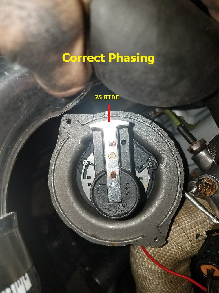
Phasing of the distributor rotor must be done on all L-series engines that run A Distributor with HT Leads and a single coil. It does not have to be done with WasteSpark Coil Packs or COP. To " Phase " the distributor rotor: 1: Disable ignition and injectors. Easiest way is to disconnect the 4 pin terminal at the Dizzy. 2: Note where #1 Spark terminal is on the distributor cap. Grab a Sharpie and make a mark on the distributor body that lines up with #1 plug terminal. Remove dizzy cap. 3: Bump the engine over till the Timing mark is at 25 BTDC. 4: Note the position of the distributor rotor in relation to the Sharpie mark you made on the distributor body. You want the distributor rotor to be centered on that mark. Loosen the two 6mm ( 10mm hex ) bolts at the bottom of the distributor. Rotate the dizzy body until the Rotor Tip is centered on your mark. Tighten the bolts. 5: Replace distributor Cap and reconnect terminals. . Congrats. You have successfully " Phased " your distributor rotor. This step is necessary on all programmable ignitions that use a distributor. Important. Phasing the distributor will alter your #1 Tooth Angle. So follow the Sync distributor steps and Lock you timing to 10 BTDC under Trigger wheel settings. With a timing light, adjust your #1 Tooth Angle to get the Timing mark lined up to 10 BTDC. 345 degree's is a good starting point. Change the Fixed Timing back to " Use Table " Burn the settings. Then Cycle the ignition Off...wait 10 seconds and then back on. Any changes to Trigger Wheel settings usually require a Burn AND an Ignition Cycle to take effect. Note: If #1 Tooth angle is out drastically , you may have the Trigger Disc upside down. There is a definate up and down side. DIY site has pictures of the correct orientation on their site.
-
Distributor Rotor must also be Phased correctly. This step is often missed but is critical to proper operation with a single coil and distributor. Covered in FSM and in MS Hardware Manuals. Attached is a text version of instructions I supply to my customers. Along with a picture of a properly Phased rotor. Note the position of the Outer slot in relation to the rotor. If the outer slot is on the other side of the rotor after proper Phasing. You have the trigger disc in upside down.

-
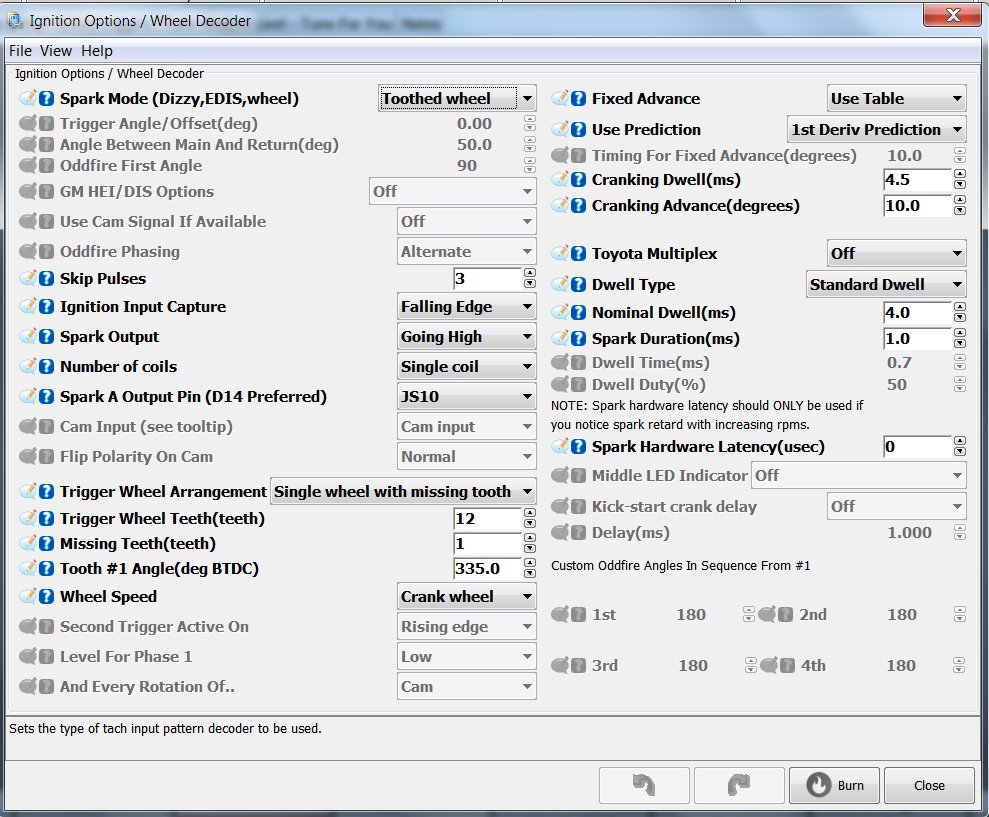
Post your MSQ. Not sure what you mean by Cranking Trigger set to " Calculated " That doesn't seem right. Never even seen that setting. What firmware version are you using? You should be using 3.4.2. Note: Trigger wheel can be installed upside down. And that will screw you royally. #1 Tooth angle will be way out. Here is a screenshot of one of my long Time customers Trigger settings. Spark A Output Pin can be JS10 or D14.. Depends on how the board was built.
-
So many questions (L28, California Datsun, Build options)
Chickenman replied to Stokked240z's topic in Nissan L6 Forum
I'm surprised that no one has warned the OP about California Datsun. I've never personally used them, and never will. From all the negative feedback on various forums this is a company to avoid like the plague. Particularly with any rebuilt engines or cylinder heads. The fact that they have often changed their names is a big Red Flag to me. I do some more research before buying anything there. Too many negative reports for my comfort... Rebello, Datsun Spirit and some other companies consistently get excellent reviews.