Chickenman
-
Posts
1052 -
Joined
-
Last visited
-
Days Won
9
Content Type
Profiles
Forums
Blogs
Events
Gallery
Downloads
Store
Everything posted by Chickenman
-
Just want to thank all of my past customers and current customers for their support. But I am taking an indefinite break from Remote Tuning. It's turned out to be too successful, so much that I no longer have time for my own projects. I haven't driven worked on my own 280Z in Ages, and I find I'm spending far too many hours staring at Computer screens. So I'm going to take an extended break and enjoy life . Time to travel and enjoy my retirement. I'll be finishing off Tunes and details with past and current customers. But I will not be taking on any new customers in the foreseeable future:. Thank you all for your support. Richard Boyk
-
Just thinking out loud here. You may ask... " But why would Steve's ignitionbe OK at WOT but not at at low RPM's? " Well, you have to look at Steve's tune and engine combo to understand why. Steve's engine is NA. That makes a big difference. At WOT it is actually easier to fire the plugs than at low loads. WOT has richer mixtures that are easier to fire off than lean mixtures. Steve is also able to run very Lean low speed and Cruise AFR's due to the big spark energy from the GM coils. I believe his last table had a low RPM and Cruise range AFR at 15.0 to one. That's perfectly acceptable with big spark energy. And I believe that Steve is running NGK BPR6ES-11 plugs with a 1.1mm or .041" gap. The combination of Lean mixture ( raises Voltage required to initiate spark ) and wider plug gaps raised the spark plug firing point to more than the damaged insulation in the GM leads could handle. This created a lot of EMI and Triggered the Anti Stall/Auto discharge feature on the GM coils. Thus the low speed misfire. I'm betting it would also be worse on rainy days if Steve took it out in the rain If it was a Turbo car, the leaking plug leads would have been easier to identify ( You had to look at them very closely to see the damage ). Boost raises ignition energy well above what you need with a NA engine at WOT. Magnacore has some excellent articles on HT Lead damage and effects. It doesn't take much to cause a problem.
-
Additional info to Steve's plight. A lot of the Auto-Discharge issues that you see on different pots are NOT due to excessive dwell. Especially on OEM GM, AC Delco and Delphi coils. Rather it is due to electrical noise or EMI. " D585" coils are particularly sensitive to EMI. Things like leaking plug wires and improper grounding can Trigger the Auto-Discharge feature. Ye you read that right. " Feature "... GM has an " Anti-Stall " algorithm built into the Logic software that will Auto Discharge the the coils if RPM falls too low . It adds timing very quickly to prevent stalling. However, it can also be triggered by electrical noise . This is what I suspect was happening with Steve's engine and the leaky GM wires. Why they failed so quickly is a mystery, but they had text book failure signs. White burn through marks and splits in insulation. I feel that even though the GM leads were stock, the HT leads were bent too sharply on an L-6 install and this stressed the insulation, causing it to fail. On GM LS motors the lead wires have a very gentle curve. Something to think about. BTW, giving credit where credit is due. I found out about the GM " Anti Stall " feature from a very advanced discussion on Ignition systems at EFI university. Paul from Pantera EFI was explaining the D585 auto-discharge problem and posted info on the GM logic coil issues and EMI. Andy Wyatt has also commented on D585 coils sensitivity to EMI. If memory serves me correct, the Pantera EFI coils do not include the Anti Stall algorithm and this makes them much less sensitive to Auto Discharge.
-
Most Suitable Circuit Race 4 Cylinder Turbo Engine
Chickenman replied to 260DET's topic in Other Engines
Audi 1.8T or 2.0T. Longitudinal engine out of an Audi A4 or Passat. Rod change and 400 WHP easy peasy. Tons of HP parts available available. Engine strong as a rock, other than Rods. ( Bend over 300 ft.lbs torque ). Lots of good forged rods available. Integrated Engineering make excellent rods. Stock pistons are good up to the 500 BHP range. Transmission. The longitudinal transmission handle up to 800 HP drag Racing. They are AWD so you would have to lock out the front drive stubs. But that should not be too hard. They do it in British Touring Cars with the Audi's. Transform them into RWD. -
That's what the heater plate underneath the Valve is for. Circulates hot water under the AAR Valve and keeps it closed when engine is warmed up. Normal operation for AAR valve with out the heater plate. Quite frankly it's never bothered me. Your big problem is you never mounted AAR valve in the stock location, which is the Top of the Intake Manifold. You mounted it on the fender well, which is not the correct location. Engine heat from Intake Manifold alone ( no heater plate ) keeps the AAR Valve quite Warm and Toasty. So it doesn't reset nearly as fast. Engine heat or coolant heat is necessary so AAR valve stays closed when engine is hot. In fact, I've never bothered with the FUGLY coolant " Hot Plate ".... and the Z31 AAR valve works very well mounted to stock location on Intake manifold.
-
Shoot me a PM and I'll give you my E-Mail. I Tune Megasquirts , but also Dabble in Haltech's and other ECU's. I have an E11 -V1 for my NA L28. Pretty sure I can come up with something decent.
-
I'll have to see if my Haltech E11 has any better stepper motor set-up. Might just go with the good ol' AAR valve setup. I've previously used a Z31 AAR valve. Have AC though, so I need an idlle load increase. Might do it with Advanced Idle control. Should be able to trigger some extra idle advance when AC is on.
-
Req- Fuel is just a number in an equation. Often you need to lower this number to gain more resolution at the Low end as Seattle-Jester mentioned. The MS Low-Z drivers can be flaky. For that reason I always recommend using Hi-Z injectors or Low-Z with resistors. The DIYAutoTune PNP Tunes are really rough from my experience. I'm taking a break from Tuning through December. Juts tying up a couple of loose tunes. But I can certainly do something in the New Year. PM me for contact info.
-
Ceramic coatings, heat shields and Turbo blankets are not just for performance. Their main function is to decrease the HUGE heat soak problems that the Turbo L-series suffer from. Performance increases are secondary, but nice. Having the Turbo and exhaust manifolds directly under the Intake manifolds is just not ideal at all. Even on a mild build, you will have issues if you do not pay careful attention to heat management. Exhaust manifold and Turbo temps vary little between a 250hp engine and a 400HP engine. Overall heat is very similar.
-
Carbon Fiber shroud around stock Nissan fan . Insulated fuel lines. Smart cookie this guy 👍
-
Before you go too far. Get that exhasut manifold off and send it out for Ceramic coating on the exterior. Well worth it. Ceramic coating the Turbine housing when it was at GPop would have been a good idea. But a Good Turbo balnket should suffice. Ceramic coating on downpipe is nice as well. Don't know whose car this is... but VERY well thought out heat management. the custom SS heat shield between Intake and exhaust manifolds is Ceramic blanket insulted on bottom side. Gold reflective foil would work as well. Note even the TIP is insulted.

-
Oil control mods for autox/road racing
Chickenman replied to JMortensen's topic in Gen III & IV Chevy V8Z Tech Board
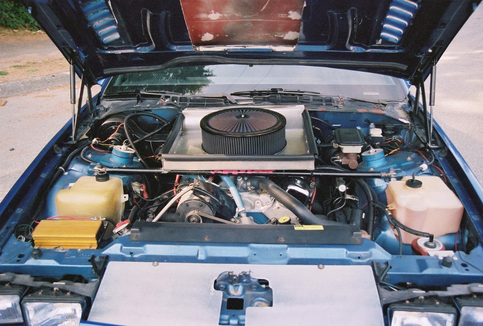
Another good option, is the Mann Pro-vent system. This is used on Corvettes and many European cars, including BMW. They are a more sophisticated design of my homebuilt oil separator. Stock GM PCV valve can go in line at outlet side. They work very well... but are kind of Butt ugly. The Pro-Vent 200 should suffice. ProVent_en.pdf -
Oil control mods for autox/road racing
Chickenman replied to JMortensen's topic in Gen III & IV Chevy V8Z Tech Board
I autocrossed, hillclimbed and ran track days with a very well built SBC for years. Not an LS, but oil control problem is basically the same. I spent a lot of time re-designing the Valve cover and PCV system. Here's what I did. 1: Choice of valve cover is very important. Mainly in the baffling. The OEM Gen 1 and 2 had a good " Chimney " style baffle with angled baffle plates inside. These are much more effective at separating oil than many aftermarket styles . Some have no baffling at all, or just a flat plate positioned below the PCV hole. These ar next to useless. 2: I use the tallest valve covers I could find. GM Performance with the factory style " Chimney" baffle plates. The taller height of the Valve cover raise the Chimney, so if your get any pooling of oil in the head, it won't suck it up like a vacuum cleaner. 3: Relocation of PCV valve. You should always run a PCV valve, but not from the Valve cover. I used a Chrysler style baffled Breather Cap where the PCV valve was originally located. These have additional baffling inside to act as an Oil separator. The cheaper ones are juts stuffed with steel wool. The better ones have both angled plates and steel wool. Both seen to be effective. 4: I then made a Custom oil separator/ catch tank where the PCV valve was attached. I used a modified CSR aluminium Radiator overflow tank for this . The tank was about 3.5" in diameter by about 10" long. Here, bigger is better. About halfway down ( a good 4 inches ) I welded a side nipple into the Can. The hose from the Chrysler breather cap attaches to this. I welded it at a tangent, so any incoming air/oil would spin in a Vortex. This helps separate the oil as it hits the side of the tank. 5: At the top of the tank I drilled a hole to fit the PCV grommet. The PCV valve was inserted at the top of the Tank and then went to the Carb PCV nipple ( Or manifold nipple on EFI ) . I did not install any extra baffling inside. The 4 " inlet below the OCV valve and the vortex spin was more than sufficient to separate any slight oil mist that got pat the GM " Chimney " baffles and the Chrysler Oil breather cap. ( Extra baffling would certainly help in difficult cases though ) Worked extremely well for may years. Autocross is the most difficult test as you are constantly buzzing High RPM, then off the throttle ( High Vacuum ) , with braking and violent cornering maneuvers. This makes it very difficult for the upper end oil to drain off as it's being constantly thrown about and away from the drains. With this modification, The PCV system was still effective, but very little oil mist got into the Intake manifold. You can see part of the CSR catch can ( Red bracket ) on the right side of the picture. Juts ahead of the W/Washer tank. PCV hose comes out of top and goes to Holley PCV nipple. You can just make out the Chrysler breather cap on the drivers side valve cover. Hose from breather cap ( 5?8" ) goes from Breather cap to side inlet of CSR catch can. Located well below PCV valve as noted.
-
Very nice project. Well sorted. Only constructive criticism I would make is don't bundle the HT Leads together like that. Even with Spiral Core wires. Bundling together like that can cause cross fire. Especially if you put a stronger coil in later... which is often required. Factory method of HT routing works very well. BTW. if you do go to upgrade the coil. The Allstar 81230 is a good choice. Modern E-Core that is has a lot more spark energy than the older canister coils. Exact same specs at the Crane LX91 . But the LX91's are getting harder and harder to find. At least the OEM Crane models. Both will work with CDI or Inductive ignition. Summit, Jegs and other places carry the Allst 81230.
-
I don't have an exact answer. But I did find this VERY detailed article by Racer Brown on building Datsun L-Series engines. It's well worth Bookmarking and reading the complete article. http://www.datsport.com/racer-brown.html Chapter 13 covers piston to valve clearance. Looks like stock Flat Tops can be machined quite a bit. ITM should be no different I would think. If you only need an extra .020" to .050" I would think it would be a non issue. Here's the important info: The piston crown of a stock piston is about 5/16-inch thick near the centre of the piston and slightly thicker toward the outer edge. This means that the stock pistons can be safely machined for valve reliefs to a depth of 0.125-inch from the top surface of the piston crown IF and ONLY if there is a radius of at least 0.060-inch at the bottom of each relief. This leaves a nominal crown thickness of about 3/16-inch at the thinnest point which, of course, is at the bottom of the relief. The crown thickness increases as the relief approaches the top surface of the piston. Normally, the remaining 3/16-inch crown thickness is adequate for any application involving the use of stock pistons. It must be pointed out that the 5/16-inch total crown thickness is an average figure; some pistons may be thinner in this area than others, so it is certainly advisable to make some careful measurements before arbitrarily gouging the pistons 1/8-inch and finding out later (the hard way) that the 1/8-inch was too much.
-
T3/T4 Turbo that spools like stock?
Chickenman replied to AlbatrossCafe's topic in Turbo / Supercharger
The thing with Turbocharged engines is that they essentially react as a larger displacement NA engine. You want to emphasize the Torque band rather than the high RPM band. We have a lot of experienced big turbo 510 guys out my way. Those who have been running Autocross, hill climbs and Road Racing have found that running a stock gear ratio such as a 3.9 on a 510 yields quicker Lap Times than running a shorter gear ratio such as 4.375's. Torque is what accelerates a car out of slow corners. The Turbo does seem to build more boost and Torque with more load on it. I have 3.9 on my NA 1976 280Z with a ZX 5 speed. The 3.9's are perfect and really allows the engine to Rev quickly. BTW, engine is not stock and will pull hard to 7,000 rpm. But if I was building a Turbo motor, I would probably go with 3.5 gears. You want to utilise that fat and flat Torque band as much as you can. -
T3/T4 Turbo that spools like stock?
Chickenman replied to AlbatrossCafe's topic in Turbo / Supercharger
T3/T4 hybrid with a .57 Trim is a good choice as well. Will easily meet your HP goals with room to spare. Will have a fairly quick spool as well. Add a good adjustable FPR to your build sheet. An Aeromotive EFI Bypass regulator part #13129 is a very good choice. You may want to consider jumping direct to 550cc injectors. Get Hi-Impedance injectors. Less hassle than dealing with the MS-2 Low-Z injector drivers, which sometimes can be a bit flaky. IMHO, buy the 3.57 revision board. Uses Small Scale Integration and is Robotics assembled. Much less chance of human error with assembly ( soldering mistakes primarily ). PM me when you need a Tune and setup. I do Remote Tuning and initial setup. Can save you a lot of time and frustration. -
I think it's one of the more accurate charts out there. By a company that sells rebuild kits, so they have to have a pretty accurate Data Base. Did you go to the Details Page? I didn't have time. It's got a very good break down. http://www.drivetrain.com/parts_catalog/manual_transmission_overhaul_kits/nissan.html I your original post you were asking about an FS5W71G... you said it was a 2wd. Parts Chart doesn't agree with that. Shows all the G models as 4wd. Now you seem to be saying you are getting an FS5W71E. That would make sense for a 2wd. Which is it G or E ?
-
Ok.. so some reserch shows that to be a 5 speed out of a 4 cylinder 1986 to 1988 4WD Pathfinder . May not be the best choice. Probably going to have stump puller low gears. Gotta run... tuning session. http://www.drivetrain.com/parts_catalog/manual_transmission_overhaul_kits/nissan.html
-
I would check the gear ratios. Often trucks have very short first and second gears compared to cars. since you Autocross, this could mess up your gearing. Especially if the Truck 5 speed was out of a 4 banger.
-
Best way to make sure you get things correct now, is to pull the front Timing cover. Next time make marks on everything with a Grease Paint Pen. I use two different colors of Marker and mark more than one area. In case the paint gets rubbed off accidentally.
-
There are factory Service Manuals on line. Can timing has to be EXACT. There are special markings on the Chain, Cam gear, Crank gear and Thrust plate that all have to be aligned correctly. Eyeballing things with " Bunny Ears " is going to end in tears. Here is a .PDF of an L28 Engine section. NA and Turbo are all the same. Read it. Then read it again and follow the procedures. EM.pdf
-
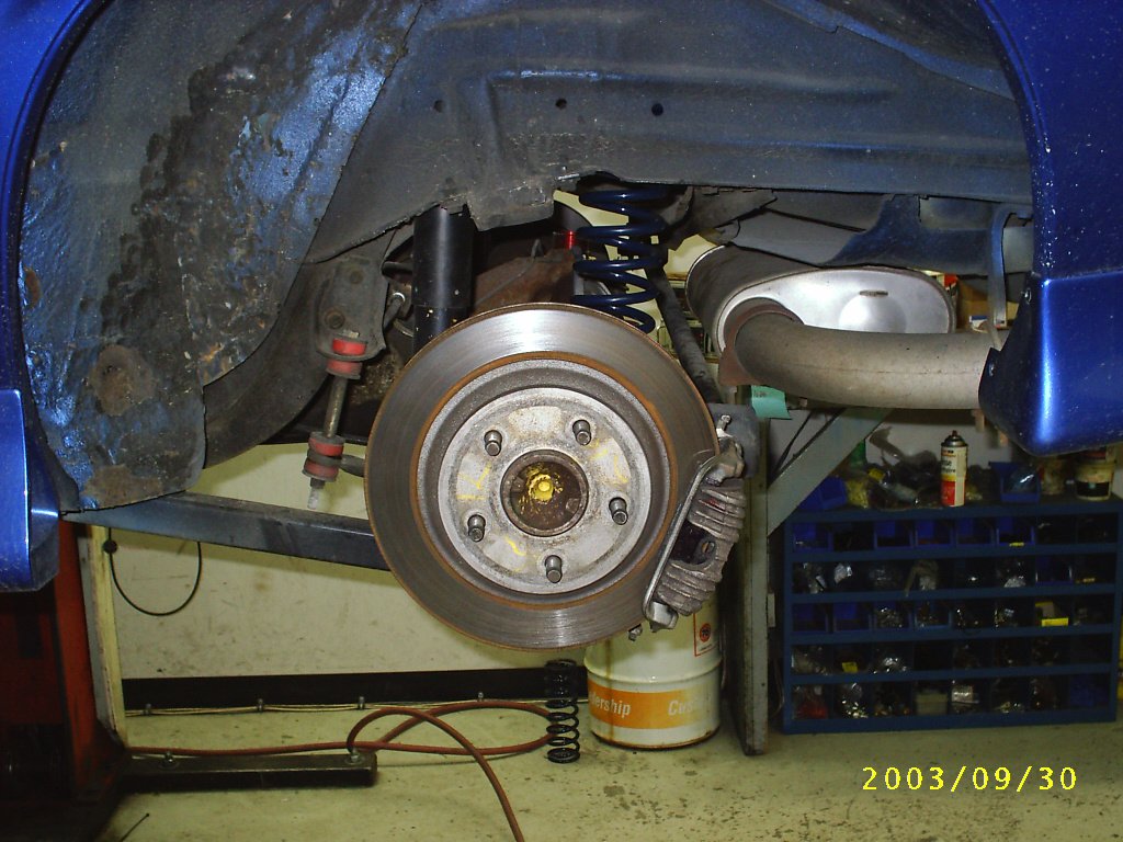
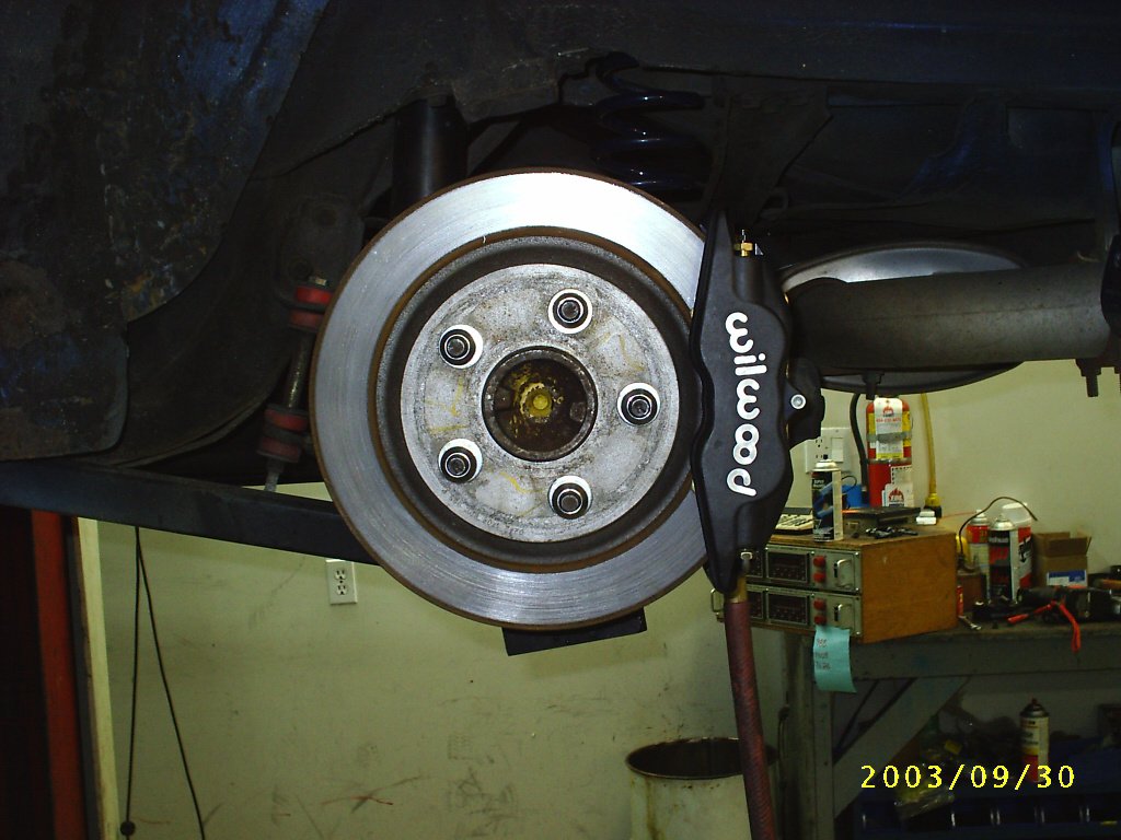
Yeah... 15's would be really tight. The 280ZX rear rotors are not 300mm though. Only 256 mm. The PBR GM calipers should clear with that rotor. You'd have to try them and see what the clearance is. Here are a couple of Pictures from my Third gen Camaro. First picture is GM 1LE rear rotors ( 300mm / 11.8" ) with PBR Calipers. This required 16" rims to clear. Second Picture is same rear rotor with WilWood Forged Superlites. The Super Lites actually had more clearance than the PBR's.
-
Personally, looking back on my Maxima caliper install, I would now build a custom adapter and use something like GM PBR aluminium calipers off Third and Fourth Gen Camaro's. ( 1989 through Mid 200's ) These are designed for an 11.8" rotor ( 300mm ) . Will have full pad coverage over the disc ( unlike Maxima calipers ) , they are extremely reliable, dirt cheap, easy to find and have a huge Pad selection. You should be able to get buy with the stock M/Cyl as the piston volume is close to a Maxima Caliper. You may need to upgrade to a 1" M/Cyl but that is not a big deal. I would eliminate the stock proportioning valve and run an adjustable one on any Track or Autocross use vehicle. So nice to be able to alter the amount of rear brake bias. Can be used to help car rotate on initial turn-in. Very effective for Autocross.
-
Temp reads high while moving, but cools while stopped?
Chickenman replied to AlbatrossCafe's topic in Nissan L6 Forum
You may have an Air Lock. Bring the system up to operating temp, with the Radiator cap removed. Watch the fluid level. It should drop as soon as the thermostat opens. Then add coolant. Rev the engine to about 2,000 - 2,500 RPM. Coolant level should drop some more. Add coolant till filler neck while maintaining elevated RPM. Then slap rad cap on. This will fill radiator completely. Of course you are running the factory Coolant recovery tank?