JMortensen
-
Posts
13742 -
Joined
-
Last visited
-
Days Won
68
Content Type
Profiles
Forums
Blogs
Events
Gallery
Downloads
Store
Everything posted by JMortensen
-
So you had brake temp issues? Boiled fluid or just cooked pads? Want to go out there this year, have more power and weight than you with 12.2 vented rotors and working on good 3" vents in the front.
-
I like the Apex Engineered arms. Others like the T3 arms. This thread details the idea behind the Apex and compares to designs like the T3. Pay particular attention to the idea of shimming the strut fore/aft, something I think T3 advertises as a feature of their design (it's a bad idea):
-
TERRIBLE design on those rears. A little refresher on flat plate control arms:
-

Wilwood proportioning Valve
JMortensen replied to grannyknot's topic in Brakes, Wheels, Suspension and Chassis
As I mentioned on the previous page, a prop valve in the front is never a good idea. As brake pressure increases, the proportion of braking done by the circuit with the valve decreases. With a valve in the front, the harder you hit the brakes, the lower the percentage of front brakes you get. This is not good, because the harder you hit the brakes, the more weight transfers to the front wheels and off of the rears. So the wheels with less traction get an increasing proportion of the braking effort as you step on the brakes harder and harder. "Proportioning Modifications We could start this section by clearly stating that you should not modify your proportioning valve. But, what fun would that be? In all seriousness, making changes to the proportioning valve to effect brake bias should be left to those with the proper tools and measurement devices, but if you have tweaked your vehicle beyond recognition, this may be your only solution to restore a sense of proper bias to your braking system. We’ll start here with three of the most basic rules regarding proportioning valve installation and selection. 1. If you have the deeply-rooted need to install your own adjustable proportioning valve, be advised that they should NEVER be installed if the factory unit is still in place. Proportioning valves in series with one another can do nasty, unpredictable things! 2. If you have the deeply-rooted need to install your own adjustable proportioning valve, be advised that they should NEVER be installed in-line to the front brakes. The effect would be to make your vehicle rear-biased before you could say “terminal oversteer.” Front brake line pressure should always be left alone – only the rear pressures should be considered for proportioning. 3. In all cases, the basic brake system balance needs to be close to optimized to start with. This is the only way that a proportioning valve can be effectively utilized. You should never assume that simply adding a proportioning valve will address all rear-bias conditions, as even the best proportioning valves must be well-matched to the target vehicle." https://www.apcautotech.com/getmedia/d958a29e-4ebf-41fd-931f-bf7e4451801b/brake-proportioning-valves.pdf
-
Wilwood proportioning Valve
JMortensen replied to grannyknot's topic in Brakes, Wheels, Suspension and Chassis
Not if the prop valve was set to a lower setting than the stock one it replaced. -
I'd make a cardboard template, trace it on one side then flip and trace on the other side. Cut with a dremel and cutoff wheel. I don't think they'll look right together with ZGs, plus you'll have the same issue with not having enough clearance for the tire with ZGs matching the body line the way everyone wants to mount them. You will probably have to find a set of matching fronts, or switch to ZGs all around and mount them wrong and slowly drive me crazy.
-
Forgot to say the flare install on yours looks fine. If you don't like them I'd try reshaping before undoing all the work. Personally I'd be inclined to cut the "mud flap" part off of the back of the flare. Never was a fan of the MSA IMSA flares they used to sell because they had mud flaps on both ends of the car, and the front of the tire exposed, which is kinda backwards from what you'd want from an aero perspective.
-
Depends on the suspension. If it has basically stock suspension you can install them lower, but when you start moving to shorter coilovers or sectioned strut housings, you start running out of room for the wheel to move up into the wheel well real fast. Camber plates make it a lot worse, especially on a 280 because the strut isolators are 3" tall vs 2" for 240Z. I cut my fenders and then put the suspension together with no spring and compressed and realized that my tire was hitting metal. Had to cut again much higher to prevent that from happening . In my case I cut the fenderwells so that they were flat from the top of the arch in the well to the outside of the quarter. Basically couldn't have cut any higher and made more room for the tire unless I had removed the whole wheel tub and rebuilt it. When the strut hits the bumpstop, there is about 1/2" space from the top of the tire to the fenderwell. I think the bumpstop is more than 1/2" long but I have super stiff springs so hopefully I won't have any issues. It's a pet peeve of mine to see ZG flares mounted way too low in the rear with really wide tires. Just obvious that nobody took the time to see if there was clearance for the tire, they just held the flare up to the body and marked and cut it there with no thought as to functionality. The other one that really bugs me is the tire and wheel being 1" from the inside curve of the flare, hellaflush style. You know that tire will hit the inside of the flare almost instantly, but still people do it all the time...
-
I went and looked. Only the one, sorry.
-
Just a quick question, Dan: I looked at doing my xmember kind of like yours and ignoring the stock bushing locations, and it seems to me (vague memory) that literally pulling the steel tube out of the aluminum pinion housing was a potential problem. Did you look into how those are attached, and are you sure that mounting the steel tube is strong enough? Would hate to see your rack disassemble itself on the track. Cool to see slotted LCA holes on someone else's car.
-
My guess: part of the tranny jack.
-
Wilwood proportioning Valve
JMortensen replied to grannyknot's topic in Brakes, Wheels, Suspension and Chassis
I didn't mean to say that your brake system was one way or the other, more just a general warning to anyone who might read this that you don't want a prop valve in the front circuit, that's all. If it helps 1.75 pistons in front and 1.38 pistons in rear is what Arizona Z Car used to sell (maybe still does???) with a hydraulic prop valve. -
Wilwood proportioning Valve
JMortensen replied to grannyknot's topic in Brakes, Wheels, Suspension and Chassis
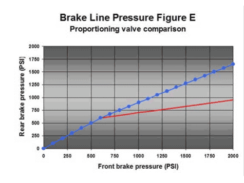
I think your problem is that you're doing the equivalent of testing a cooling system thermostat by putting it in a pot of water on an electric blanket. Autometer brake pressure gauge goes to 2000 psi. I don't know what "normal" brake pressures are, but I suspect that you're WAAAAAAAY too low to test them in this manner. https://www.autometer.com/2-5-8-brake-press-0-2000-psi-no-tubing.html EDIT--If you put those gauges in front and rear and then turned the dial, then you could get useful info. FWIW I had a brake system where adjusting the prop valve made no difference at all, using 4x4 front calipers and early ZX rear disc. The problem was that the rears were so undersize that it didn't need to be reduced at all. If that's the case for anyone, the solution is bigger rear brakes or smaller fronts, NOT to put the prop valve in the front circuit. Hydraulic prop valves are not "proportioning" so you don't get a linear 70% or whatever amount of the pressure. They have a knee, after which the pressure falls off. What this means is that if you put one in the front brake circuit, the harder you step on the brakes the less front brake pressure you will get. Anyone who has looked at brake balancing knows that the harder you step on the brakes, the more weight transfers to the front, the less pressure you want in the rear. So it's a really bad idea to put a prop valve in the front brakes. -
37 Degree Flares for Brakelines
JMortensen replied to NCchris's topic in Brakes, Wheels, Suspension and Chassis
AN uses single flares, not double. Chamfer the ends of your tube before you flare (very important!), then use a magnifying glass to inspect for cracks. -
Sway bar calculations (check my math)
JMortensen replied to JMortensen's topic in Brakes, Wheels, Suspension and Chassis
Just FYI, the above methodology is wrong. Good thing I asked. "Got this response elsewhere and doesn't make sense to me, but probably right and I'm probably wrong:"If that's the case, I think the 1.25" with .125" wall mounted at 5" out vs. your 1" solid mounted 8" out will still be a fair amount softer. Even a .25" wall would still be softer. Something like a 1.375" bar with a .188 wall would seem to be pretty close wheel rate wise to your 1" solid."When I asked what part of the calculations I messed up, I got:"Not sure -- I just used own spreadsheet I have. For the raw bar number I think my numbers same as yours. But when I look at wheel rate of the bars I think you need to use motion ratio squared. So for 8" point that is 8/11.5^2 = .484 and for the 5" point it is 5/11.5^2 = .189. So you really need a bar that is .484/.189 = 2.56 times stiffer. Hope that makes sense." and "Yes, you need to square the motion ratio of the swaybar to convert it to a wheel rate.In addition, the calculated rate of the swaybar is really in lbs/0.5". This is because the analysis assumes that one arm of the swaybar is held fixed and the tip of the opposite arm is moved 1". This is like rolling the car only 0.5". So if you want to do any math that compares the swaybar rate at the wheel to the wheel rates from the springs on the car, you need to double the calculated swaybar number so that it is in lbs/inch. Virtually every swaybar number you will ever see published is really lbs/0.5". If all you care about is making a new swaybar that has the same rate as the existing swaybar, none of this will matter." -
I need to replace my swaybar I'm trying to figure out the math here and just want to verify that I'm doing this right, because I usually **** it up. Plan is to move the sway bar attachments on the LCA inboard for brake duct clearance.I measured the LCA length at 11.5 from inner pivot to ball joint, the distance from the sway bar attachment to the inner pivot at 8 and a new further inboard spot at 5 inches. Drew it out on graph paper, calculated for 3" of travel which I think is probably more motion than I get at my spring rate, and found that the outer pivot moved 2 1/8" and the inner moved 1 3/8". Then divided to get a motion ratio multiplier of 1.54. Using a sway bar rate calculator here http://www.gtsparkplugs.com/Sway-Bar-Calculator.html I input the width of the center section of the bar at 32". This is a stock bar with a bend in it, so I measured the full length with the bends, not just the width to the arms. The arms, which angle out are 11" long and the longitudinal distance from the control arm pivot to the control arm is 10. The bar diameter is 1". I'm getting 297 in/lbs. Then using hollow sway bar calculators, I'm trying to hit about 1.54x the spring rate, so call it 450 in/lb. Same calculator with 1.25" OD, 1" ID, 32.5" wide, 10" arms no splay is giving me 448 in/lb. Does all of that sound right to the more technically proficient?
-
I don't have those lengths anymore. If they're in the thread, great. If not, I gave the tech drawings to Joe @ Chequered Flag Racing. He's still producing them.
-
Puhlease. I'm a doggy door salesman, not an engineer. If you see something, say something. The life you save could be mine. As to TTT, just read that one comment below by Dan where he says running .3* toe in results in 360 lbs side loading on the strut shaft if you don't reshim the strut. The thing that REALLY bugs me about the TTT stuff is how people just shim the strut back to try and center the wheel in the well. NOT a good idea, but if you bring it up, "Well Jim Bob did it and he didn't have any problems!" I don't know how to do the reshimming accurately, but when I had my similarly modded stock arms I assembled the suspension with no springs, compressed the struts and then tried to make sure the strut was centered in the monoball. (Illuminas at that time, so I was centering the 12mm shaft in the 15 mm monoball). It was tedious and I doubt I got it correct enough to eliminate that strut loading issue. There is probably a better way, but I'm not aware of anyone even attempting it aside from me. I made this drawing before years ago, and I can't find it, so here is an updated shitty drawing:
-
Here are most of the relevant posts from the other thread. If you need the full context read the other thread in its entirety:
-
Yes, that's the point. By freeing up the strut you eliminate side loading on it. Search the thread I posted and read the Milliken and Milliken quotes from Race Car Vehicle Dynamics, they explain the problems with H arms and the benefits of A arms.
-
I'm going to beg to differ since it's my design. Here is the thread it came from: https://forums.hybridz.org/topic/62776-yet-another-rear-control-arm-design/
-
What year? My 70 with full interior, Autopower roll bar, L28, 5 speed and R200 weighed in at 2350. If it's a 72 I think you gain 100 lbs, but probably still at 2350 without the bar and with R180 and L24.
-
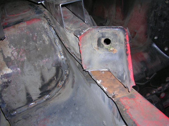
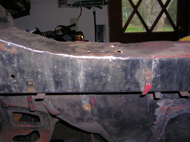
This is pretty unbelievably terrible. Sorry to be blunt, but if you don't fix that you're going to end up losing steering while driving and hurt yourself or someone else. Not good. I would take the xmember, hack the ends off, move them forward so that engine clearance is no longer an issue, weld some nuts inside the frame rail to bolt it up, and fab up a new xmember, possibly using the steering rack mounts from this one. Or look at buying an aftermarket one from Apex Engineering or building something similar. A round tube won't take up as much space as the stock one, and you could move it forward an inch or whatever you need for clearance and it will affect the Ackerman but it will be a hell of a lot safer than what you've got there. Leon hinted that you had better have that engine hard mounted to have it that close to the xmember but didn't spell it out specifically. Over the years seen quite a few radiators damaged when the engine moved forward under braking and the fan hit it. The drivetrain moves around quite a bit. If it's not solid mounted you need to have a bit of space. I think it depends on the mounts, but on a Z I wouldn't go less than 3/4". That's gut feel though... https://www.apexengineered.com/store/p7/Front_Tubular_Crossmember.html
-
Moving tension rod mount outboard
JMortensen replied to fusion's topic in S30 Series - 240z, 260z, 280z
ZX has a rear mounted rack. I think the steering would be a real problem with a forward TC rod. If I understand your idea correctly, then yes, hacking the part that protrudes into the engine compartment off and welding on a new plate and then running a bushing or rod end or whatever would certainly be easier and it probably wouldn't significantly change the length. Agree with the comment above though, do whatever you do on both sides. -
Moving tension rod mount outboard
JMortensen replied to fusion's topic in S30 Series - 240z, 260z, 280z
By using most of the aftermarket TC rods, where the rod end bolts into an adapter that bolts into the bushing cup, you're effectively shortening the rod anyway. I think you can shorten the rod a little bit and not see much difference in how the car drives. The more you change it, the bigger the effect on the caster sweep, so I'd keep it to the bare minimum. Also, having removed the TC buckets from a chassis personally, I can tell you that they have about 457 spot welds per side, and it's tough to remove them without messing up the frame rail underneath at least a little bit. This would be 877x easier with a rotisserie too. All stats pulled straight from my ass, BTW.