JMortensen
-
Posts
13742 -
Joined
-
Last visited
-
Days Won
68
Content Type
Profiles
Forums
Blogs
Events
Gallery
Downloads
Store
Everything posted by JMortensen
-

Do I Need Bump Stops With New KYB's?
JMortensen replied to Mayolives's topic in Brakes, Wheels, Suspension and Chassis
Don't post in the FAQ section. Nobody can reply. KYBs are comfort shocks. Konis are better for your uses. -
Circle Track Sway Bar
JMortensen replied to JMortensen's topic in Brakes, Wheels, Suspension and Chassis
Clark, I was taking it as advice and appreciating it, so thanks. I got that same feedback elsewhere Richard, will probably be revising. The good news is I won't have to figure anything out next time, just duplicate with thinner metal. -
Circle Track Sway Bar
JMortensen replied to JMortensen's topic in Brakes, Wheels, Suspension and Chassis
Interesting stuff Clark, thanks. 1. Same weight as MSA 1", so good there. Haven't run a rear bar in 20 years, so call that a weight savings... I will say that the ST rear bar is a LOT lighter than the MSA rear bar, you don't have to drill holes in the chassis to mount it, and if you space it back a little it doesn't bind. I have dents in my frame rails from the MSA bar end links hitting them, so back in the 90s and early 00s I was definitely doing it wrong. 2. According to my WTW, I'm at .99 degree for 1g, and I have a lot stiffer springs 550/600. I am a lot wider, maybe that makes the difference. So may need to stiffen up later as the car should be capable of more than 1g. Haven't measured g's yet. 4 and 5. Yes, definitely needed the adjustment on the bottom, and the double shear means I can run a clevis pin too. One thing I forgot to mention is that when I welded in the mounts on the previous iteration I had an end link solidly bolted in. This made it difficult to slide the end link into the control arm mount. This time I took a HF blister pack from a tool I had bought and used some of the clear plastic. Just cut out a square and punched out a 3/8" hole in the middle and put that in between the rod end and the arm before I welded. I measured the plastic at something like .006 or .010 thick, can't remember, but now if I want to move the rod end it slides nicely to the next position really easily. Probably would clunk in a street car, but I'm doubting I'll hear it or care... 6. I calculated the spring rate and matched it up. I can go stiffer or softer, so hopefully I'll have a setting that works, but won't know until I get it back out again. I have some spring options, so might need to change those to get what I want, and if it needs stiffer anyway, no biggie. -
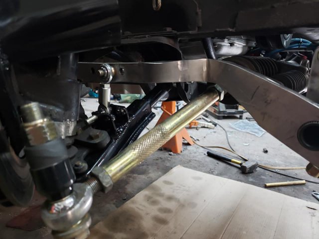
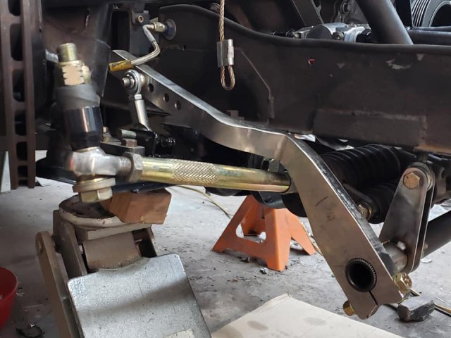
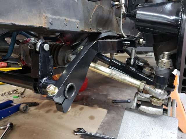
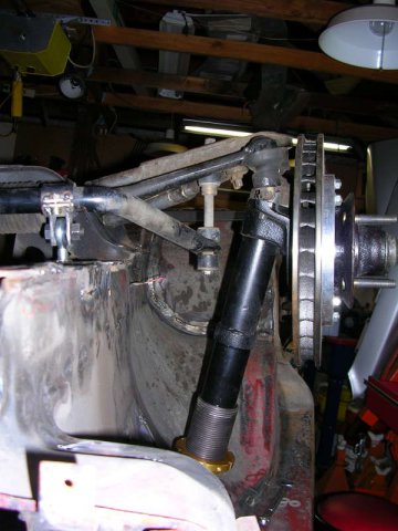
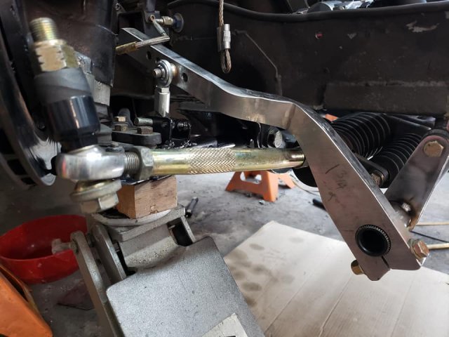
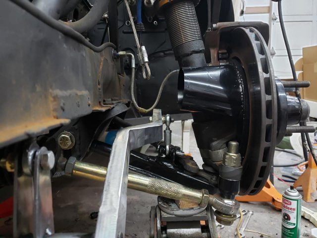
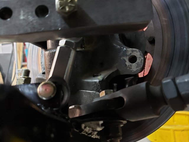
One of the main things that I wanted out of a circle track style hollow bar with splined ends was lighter weight. Turns out the arms that you can buy off the shelf are 3/4" thick steel and are REALLY heavy, so this ended up being a lb or two heavier than the modded MSA bar that I took off. If you're looking at this for a light weight bar, look elsewhere. This is probably revision 457 of my sway bar setup. Some of the highlights of my previous attempts: Started with an MSA front and rear bar set. I had originally bought MSA front and rear bars. Then I had changed the rear end links and they ended up hitting the frame rails. Then I got an ST rear bar and modded it by drilling out the bushing saddles and adding zerks. Made double shear control arm attachments for modified stock arms. I tried to get a guy who custom bends hollow bars to make me one, can't remember the name now (Simonson???), but finally gave up after repeated attempts to contact him, including ones like: "I've got cash in hand. Want to buy a bar. You have made the sale. All you need to do is answer this email." No reply, so I finally decided to do the same thing a friend of mine had done successfully: I cut the ends off of aftermarket MSA front and rear bars and welded on 3/8" x 1" steel bar and drilled the new ends for adjustment. Then I mounted the bars on heims joints to reduce friction (more on this later). Then I mounted the front bar on top of the frame rail for splitter clearance. Then I installed an oil cooler, and the bar interfered, so I moved it back underneath, and that is what led to these latest revisions. The previous bar in its last iteration had the 3/8 x 1" bar stock welded on at an angle so that the end links leaned in towards the fenderwell significantly. I had found that this would give me the best clearance around the suspension parts. Before I ever ran it, Richard (260DET) pointed out that this would give me a falling rate sway bar, so I revised it by bending the ends vertical. There were several adjustment holes on the bar, but after fixing the end link angle, the end links bottomed out on the bar or the control arm mount that I built, so I could only use one hole per side, so I basically spent a lot of time cutting up a sway bar and welding crap to it and ended up with a non-adjustable sway bar with a bunch of useless shit welded to it. I probably should have left it the way it was, but even in that state the whole thing was pretty janky, and the only saving grace was that my spring rates were so stiff that it probably kept the bar from being used enough to bend the ends or snap the welds off. People have a big problem with welding to a spring, and I get that, but having done it and knowing others who have done it on race cars with stiff rates (meaning not a lot of sway bar twist) it works. It's not ideal, and I'm not saying that it is, but it works. It did hold up for 5 or 6 autoxes with 2 drivers but I wouldn't put this up as my best fabrication project. I wanted the new one to be functional, mount on the bottom of the frame, fit under the splitter, and clear the power steering ram on the rack which sticks out quite a ways on mine. Mounting on heims is controversial. One of the main things I was after with my suspension was reducing friction, so when tube80z suggested this as an alternative to poly, I was immediately interested. The idea is to have ears on the sway bar that connect to a rod end that is installed into the frame. This allows the sway bar to move up and down much more freely, but it also allows the sway bar to twist and doesn't restrict its shape while it twists. The bar should make a (slight) S shape in the center, and allowing the movement that the heims joints do should make it just a little bit easier for the bar to do its thing. I don't know that this is a huge deal, I think the bigger thing is allowing the bar to move freely, but there are IMSA and GT cars running this kind of setup, which is what tube80z showed me, and that's what convinced me to try it. I already had reinforced the stock sway bar mounting areas with a plate on top and bottom of the frame rail, and tubes connecting top to bottom in the front and back of the plates. I had used a pretty thin walled tap tube, but later decided it was probably too flimsy, so changed to a much thicker walled tube welded nuts on top and bottom. I'm still using those tubes. This still produces a lot of "WTF are you doing?" kinds of comments. Back in the day Cameron (Heavy85) was pretty outspoken as a critic and Coffey seemed to like the idea IIRC. You decide whether it's great or a waste of time and effort or doesn't make any difference at all. I was convinced enough to do it. The stock bar has the dip in the middle for oil pan clearance, and with the ears I had on the stock bar the center part of the bar would hit the splitter as it moved. I was hoping that the straight center bar would improve things, but no, just created a different problem: it hit the power steering ram. I figured I could use longer mounting ears to drop the sway bar down away from the ram. It was tough to see how everything would line up when it was all done, so I made them longer than necessary. I spent a lot of time making sure that the end links wouldn't bind and that the bar could move all the way through the suspension travel without hitting the ram or anything else. Had to trim sections off of the arms as well for sway bar clearance. The arms are very thick and strong, and I was only able to put about 1/16" bend in one with my 12T press. Was thinking of cutting or grinding them thinner so that I could bend them, or just giving up, but found a local metal fab shop with a huge press. Took it down there and explained what I wanted and watched/helped as the guy bent them to fit. Also wanted double shear so I welded an extension to the arms as well, and used high misalignment bushings on both ends to keep it from binding. Found that 3/8 male and female rod ends weren't short enough, so had to trim the threaded part of both to get them short enough, but there is no binding. The front adjusting hole on the arms is for the droop limiters, not a sway bar adjustment. Cleaned it all up, welded, painted, stuck it in the car and the ends of the arms where the bolt holds the splines tight hits the splitter. Now that I had it all on the car though, I could see that the ears were longer than necessary. Cut an inch off of the ears, redrilled and they're on there now. I haven't put the splitter back on, but I'm sure everything clears. Couple pics of older iterations in here as well. Off topic: the brake duct doesn't clear the arm, so one of my projects for the winter is to point the brake duct inlet forwards for clearance.

-
Suspension Setup Gurus....help...
JMortensen replied to Ironhead's topic in Brakes, Wheels, Suspension and Chassis
As far as how much is too much on the spacers, I think fox body mustang guys run a lot, IIRC it's like 2 or 2.5 inches on that chassis. The other common solution would be to bend the steer knuckles. DP Racing does this for 510 knuckles to give Ackerman and to fix bumpsteer, no reason it couldn't be done to lower the tie rod attachment. Friend of mine had some bent for his 510, IIRC they heated them red hot with a torch, bent, then heat treated for strength. Alternatively could just take a huge chunk of billet steel and make a forked end so you'd get double shear on the tie rod, which would be better but is a huge PITA and wheel clearance is a real problem on the Z. I've even seen sheet metal used in boxed structures that are welded for strength, and I'm sure that could be done if you were so inclined. I'm skeptical that it would be worth the effort on a 50 yo Nissan strut front end. My guess is that there's enough flex in the other bits that the gains probably wouldn't be noticeable. The angle of the arm itself is kind of deceptive. You want the angle through the joints to be parallel. Since the ball joint sits entirely on top of the arm, that means that the arm will need to angle down to get the pivots level. A stock tie rod pivot is much closer, but still the angle of the tie rod isn't the the same as the angle of the joints. So if you line up the arms, you'll still be significantly off. Best way to fix bumpsteer is to measure it. I don't know if the guy who wrote the JTR manual that said to move the LCA pivot up 3/4" and out 1/4" actually measured anything, but when I measured on my stock(ish) front end 20 years ago, up 7/16" was what minimized it best. I suspect maybe he was looking at the arm angles, but that's a guess. I'll make another thread. Those pics were taken when I was still figuring things out. Got it all done and then couldn't put the splitter on, redid the front mounts over the summer and haven't touched the car since then, but it looks significantly different now and the drop downs are... different. -
Suspension Setup Gurus....help...
JMortensen replied to Ironhead's topic in Brakes, Wheels, Suspension and Chassis
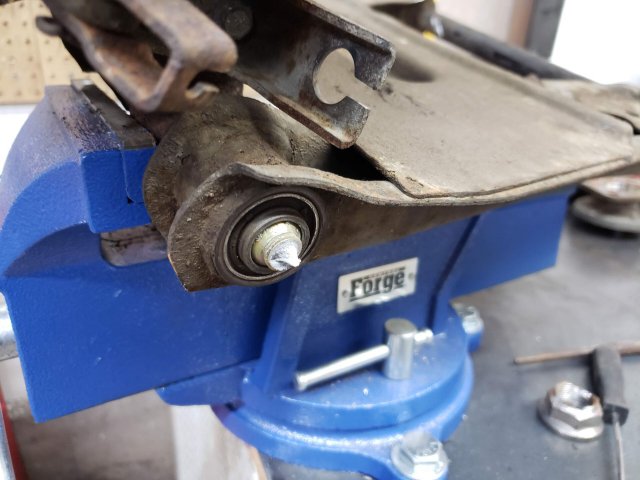
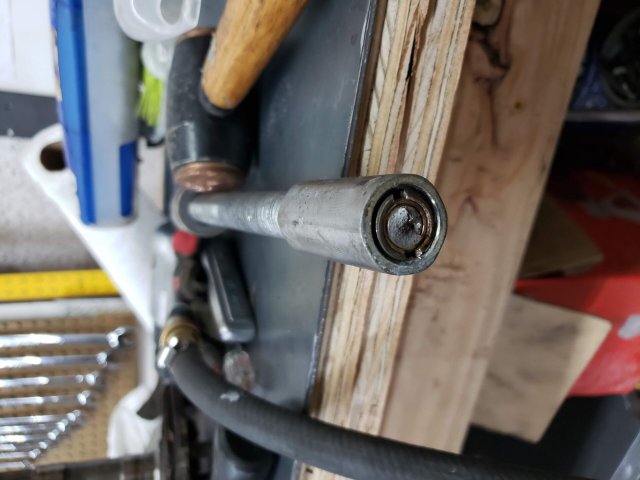
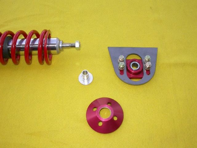
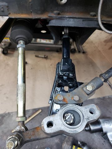
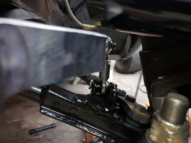
Couple pieces of advice from personal experience. Moving the rack forwards or back makes very little difference in practice. I moved mine back as tight to the xmember as possible, then decided to do a Woodward rack and the ps servo is right in the way, so I had to move it forward to fit. Had moved the rack back purposely to add Ackerman, and then a year or so later found a link that showed how to sketch it out on graph paper. Did that and found that the difference was tiny, so then when I had to move the rack forward, did it again, graphed again and ended up with something close to parallel steer. Not ideal for autox, but hey, throw some static toe out at it and it's just not a big enough difference to sweat over. As to using a lot of bumpsteer shims to move the tie rod down, I was running my car like that for a while, it was good enough. Bolt is better than a tapered pin though, according to an engineer friend of mine. He said the tapered pins move around more and are more likely to break, and also that the thin circle track bumpsteer shims that I was using are not the best. He suggested running a really thick walled tube tapered down to fit on the rod end. I don't have a lathe, so I welded a rod end spacer to some thick wall tubing and then ground it to the right length with my belt/disc sander. Took a while, but it worked. Here's a pic of the old and new versions. I have an extra length of this tube so if you want to do this give me $8.30 for flat rate shipping and I'll mail you a chunk.
-
I think at under 200 ft/lbs you're probably going to be OK. One of our members, zredbaron, has a 300bhp L31 (I want to say it was more than 250 ft/lbs) and he's been through 3 different types of CVs IIRC and destroyed 2 diffs, snapped a mustache bar, I might be forgetting one or two other mishaps. EDIT--If you do go with CVs, especially on a race car, safety wire them. They seem to have a way of loosening the bolts.
-
Rolled my Z not sure if it's repairable
JMortensen replied to Cheesymamba's topic in Fabrication / Welding
Some people cut the roof off and reattach to do roll cages. That kind of thing would completely fix your car. -
Drum brakes for a racing application
JMortensen replied to AydinZ71's topic in Brakes, Wheels, Suspension and Chassis
That is not what I remember. Maybe it was Coffey. Or maybe my memory is broken. Wouldn't be the first time... -
Helical Limited Slip Function and Torque Bias Ratio
JMortensen replied to JMortensen's topic in Drivetrain
This is WAY overstating the case. You could say the same thing about Nissan's CLSD, since it has preload springs in it too, but they will definitely spin a tire if you lift it off the ground, I speak from personal experience. That said I agree with the general advice of not jacking up one side and driving the lifted tire. Traction-Loks are fairly weak clutch LSDs that are prone to destroying their little clutch tab protector shim thingies. The Nissan CLSD is way more aggressive by comparison due to its ramp design to load the clutch packs and stronger too, by comparison. Richard, I had seen an engineer whose opinion I really value talk up the Wavetrac maybe 8 or 10 years ago. Tried to find it for you and failed, but from what I remember I think it's not as aggressive as a ramp style CLSD, but significantly better than a Truetrac or other "standard" helical design. -
Using 5/8 bolt in place of spindle pin
JMortensen replied to fusion's topic in Brakes, Wheels, Suspension and Chassis
The main issue with the 5/8 bolt is that it is a couple thousandth's smaller than the pin, so it is loose in the spindle bore. If you torque the bolt down so that it doesn't move, I think you're OK to use the bolt with no huge issues. Torquing the bolt shouldn't be a problem with poly bushings in theory, but probably is in practice. The idea with poly is that the sleeve should be tightly held by the bolt, or the nuts on the stock pin. The bushing is intended to rotate around the stationary sleeve. The problem is that the bushings are almost always way wider than the sleeve, so you have to torque the crap out of the bolt in order to hold the pin stationary, and I can tell you from personal experience that this makes the suspension REALLY hard to move. My guess is that most people don't actually tighten this all down correctly, they just tighten it "enough" and if that is the case, then the bolt can actually pivot in the bore (wearing the bolt), and the bushings can also move around the sleeve. Whichever requires less force is more likely to happen. If you're going with a rod end style control arm, this is really not an issue at all. Torque it down tight enough and you're good. The solution with poly is to sand the bushings down to reduce the bushing width, so that you don't have to torque the bolt to 100 ft/lbs to compress the bushing enough to lock the sleeve in place. In addition to cutting the length of the bushing down so that there isn't so much compression on the bushing, another thing to do would be to sand away a lot of the surface area on the outer ends so that the resistance to the bushing spinning is reduced. In combination these two things will still control toe change because the bushing extends into the control arm and you wouldn't be removing that part but it will reduce friction A LOT. After modding the bushings another thing to look at is adding zerk fittings to the outer ends of the LCA so that the bushings can be greased. Easy to do, works great. What doesn't work is zerks on the inner bushings; the bushing saddles aren't tight enough, so rather than going in between the bushing and sleeve, grease added just squishes out the corners of the bushing saddles. If you're installing poly bushings, watch this video first and consider the above mods to improve their function. This video talks about a Miata poly bushing with a better design that has these features incorporated, along with cross hatching that allows lubrication to stay in the friction area between bushing and sleeve, which is far better than what Energy Suspension is making for Zs. Probably not enough market to justify doing this for a Z though... -
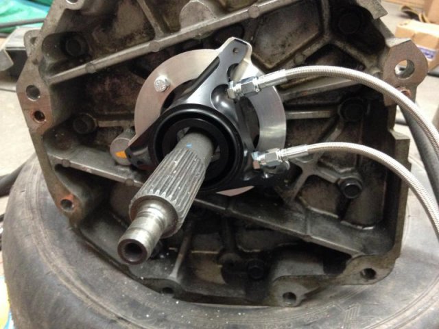
Meet the new spindle pin, same as the old spindle pin
JMortensen replied to JMortensen's topic in Drivetrain
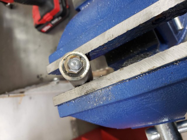
I'm not worried about getting the pins out. What I really want to do is save my brother in law's tool. I made my own puller with parts I bought from a guy on classiczcars.com 20+ years ago, but IIRC it had standard allthread, a standard lug nut, and a metric lug nut welded to it. I gave it to the BIL, he broke it and replaced with this. This one is much nicer, so I'd like to save it. -
Thanks for the kick ass design, Nissan! I'm trying to use my BIL's spindle pin puller, and I actually broke the pin itself in the end of the tool. Last one I had was a standard lug nut welded to a metric lug nut IIRC. This one is my BIL's and looks like it has a sleeve with an insert, and then a timesert in that. Hoping I can disassemble and get the piece out. Tried to drill it and was going to tap and then put a bolt in and weld and pull it out that way, got about 1" into the pin and the drill bit broke. Tried welding a nut onto the end, just twists off.
-
Had an issue with my ZX 5 speed twice, friend had the same with her Z or ZX 5 speed once, where the 5th/Rev shift rail would move out of position on its own. On mine, this caused the trans to go into 2nd and 5th simultaneously while on track (friend driving) and the rears locked and narrowly missed a brick corner worker's stand. The other two times was on the street. Friend's Z got locked into 2 gears also, think it was 1st and 5th that time. Last time was something like you described. This is 25 or so years ago, can't remember the specifics. The track one was fixed by fairly violently moving the shifter through all the gears. The other times the trans was dropped, the little access plug with the detent spring and balls was opened up and the rail moved with a screwdriver. I can't remember if it's the top or bottom plug for 5th/R. The other thing that occurs to me is that I once had a bad clutch slave and it was leaking pressure. The car would shift into all forward gears, but not reverse because the trans never stopped moving and there is no synchro on R to help it in. Something that hasn't happened to me that I've read about is the shift fork roll pin shearing. When this happens you can move the shaft but the actual fork doesn't move, it just slides on the shaft. Racers used to swap out the later aluminum forks for the earlier steel ones and double pin the forks with solid pins, or use the hollow roll pins and run safety wire in them to double it up. Yours sounds more like the first issue or the sheared roll pin. I'd pull it and pull the detent ball and see if the detent groove for neutral isn't lined up with the hole first, then open the case and check the fork of the detent is in the right spot. If you shift and see the shaft moving but it won't go into gear, then that tells you probably the fork isn't moving or is broken. Should be a fairly easy fix as compared to rebuilding the whole box.
-
Eibach Springs - Front sits high... *pics*
JMortensen replied to PCressey's topic in Brakes, Wheels, Suspension and Chassis
No, on poly the sleeve is captured by the frame, and the bushing rotates around the sleeve. When you set it down, everything rotates and compensates. On rubber it's all bonded together, so at full droop it should be maxed out one way, and if you tighten it with the bushing relaxed, then when you set it down it will be significantly torqued already, then going over bumps twists it further. It will work fine, just a lot of people freak out because "MY SPRINGS ARE BROKEN!!111!11!1!1!" -
Eibach Springs - Front sits high... *pics*
JMortensen replied to PCressey's topic in Brakes, Wheels, Suspension and Chassis
If they're bound then they're not doing anything, but if they're not then they're softer than the rest of the spring, hence the progressive part. The Tokicos are worse, and it's been an ongoing topic since the 90s. It is as designed though. If it bothers you get a non-progressive spring. Personally not a fan of progressive springs.- 48 replies
-
- 1
-

-
- suspension
- springs
- (and 1 more)
-
Let's talk lighter weight clutches for LSX motors
JMortensen replied to 280Z-LS3's topic in Gen III & IV Chevy V8Z Tech Board
If you're not driving in traffic and just going for canyons or to the track, what I have would be OK. The big problem with the multi-disk clutches is that they can overheat pretty easily. Stop and go will kill one, as will slipping it too much with the sintered iron clutch disks. -
Let's talk lighter weight clutches for LSX motors
JMortensen replied to 280Z-LS3's topic in Gen III & IV Chevy V8Z Tech Board
He already stated the reason; the stock flywheel and pp is 60 lbs. That's a big deal to me too. It's going to make the transmission significantly slower to shift, as well as just slowing the car down on accel, reduce engine braking, etc. I would like to drive one with a light flywheel and see how that is in actual driving. Might be good enough, even though it still sounds stupid heavy Also should have pointed out the hassles with setting up a button clutch. You don't just slap it in. Need a special throwout bearing (more $$$) and have to take measurements from the bell housing and shim the bearing to the right depth, then limit the hydraulics so you don't push the bearing too far as you can pop the slave apart inside the bell housing or damage the pressure plate springs. It's not rocket science, but takes a little doing. I got my slave from QuarterMaster. https://www.quartermasterusa.com/qm/components/hydraulic-release-bearings-components/tri-lite-release-bearings-hydraulic-release-bearings-components I can't remember the reason, but my stock flex plate also wouldn't work with the button clutch, I had to buy an aftermarket one to put it all together (more $$$).
-
Let's talk lighter weight clutches for LSX motors
JMortensen replied to 280Z-LS3's topic in Gen III & IV Chevy V8Z Tech Board
I don't know what a step or strap clutch is, but I have a NASCAR style button clutch in mine. Flex plate for the starter and tiny clutch mating surface with two 7.25 disks. I think the flex plate and clutches came in around 20 lbs. I can tell you it revs and shifts fast. Carb isn't really dealing very well with it, so will probably go FI with it at some point. Needs an instantaneous huge squirt of fuel, but then needs to taper off fast, accelerator pump cams just aren't shaped right. It's really grabby and wouldn't be fun in traffic, but I think it would probably be doable if necessary. They have carbon clutches that are better suited to driving on the street, but they're way more expensive and mine is a trailered race car, so I went this way.
-
That top hat from T3 won't pivot with the strut as it changes angle, so it will allow for the strut to twist as you're steering, but I fear you're going to really chew through the threads on the coilover sleeves even more than they normally do. The other solution is an adapter between the top hat and the monoball which allows the top hat to follow the angle of the strut, and uses the monoball to twist. Arizonazcar.com has a part that fits the bill, the silver bit in this picture: http://www.arizonazcar.com/coilover.html Last option is the Ground Control setup. They don't have any pictures of the important bit on their site, but there is a steel concave cup part which rides on a needle bearing like the T3 setup, and then an aluminum ball section that rides in the steel cup, and this allows the spring to change angle with the strut. It also turns the camber plate into a wear item, but it's what I have. https://groundcontrolstore.com/collections/s30-camber-plates/products/camber-caster-plate-z-car-pair
-
Drum brakes for a racing application
JMortensen replied to AydinZ71's topic in Brakes, Wheels, Suspension and Chassis
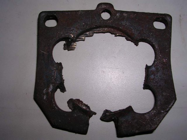
I did a quick check, and the stock front rotor is 10.6, so you'd want to get as close to that diameter as possible, since you can run up to the same diameter rotor. The early ZX is 10.5, later ZX is 10.2 according to rockauto.com. If you're going to make your caliper brackets, I'd use an early rotor and a late caliper. Or if possible find a rotor with a less deep hat. Early ZX has really deep one, the rotor is probably 3" back from the axle flange. Also re: drilled rotors. I pushed the piston through that brake pad with drilled rotors. I was at the track and needed to drive home, so I went to the local parts store, bought their shittiest pad, slapped it on and drove home. Changed them before the next race, but never even surfaced the rotors and there were no cracks at all between the holes. I worked on Porsches at that time and we routinely replaced rotors when the cracks were nearing the next cross drilled hole, but mine never cracked at all, front or rear, after lots of abuse. I will say that they make a weird buzzing noise when you get them hot. My explanation is the heated air is being released from the holes as the rotor turns past the brake pads, successively venting each little hole along the way. Not a problem, but it's kinda strange. The bigger issue is that you're taking away material. I guess the idea is that the cross drilling helps to cool the rotor, but more mass means it can absorb more heat, so ??? If you're running stock brakes in front I'd suggest a couple of 3" vents per side. Katman, who prepped a lot of ITS cars, posted about using a soup can with a slot in it to get air to the outside of the rotor, and warned against cooling only the inside. You might be able to search his threads to find. Probably close to 20 years ago now. -
Drum brakes for a racing application
JMortensen replied to AydinZ71's topic in Brakes, Wheels, Suspension and Chassis
Totally agree with this. Also, the early 79-81 ZX rear disc is not an upgrade in stopping power over the drums. It is possible to get enough rear braking with the early ZX and the stock front calipers, but any front upgrade will overwhelm the rears. I had Toyota fronts and the early ZX and couldn't get enough rear braking, eventually put the stock front calipers back on and was able to dial it in, but then I would boil the brake fluid all the time. Got to the point where I no longer got an adrenaline rush when the pedal went to the floor. That's a bad sign LOL. Also got the fronts so hot the brake pad lining just abandoned ship and a punched a hole through the backing plate. Rears had pad material coming off in chunks. To my discredit though, I was trying to run Porterfield's R4S street pad. Not a good idea... I never tried the 82-83 rear brakes so I can't tell you if they're any better. Definitely lighter, those early calipers are HEAVY and the pads are TINY. I would suggest looking at what other EP drivers are doing for brakes. Greg Ira is the 3x national champ. See if he has any recommendations for you. If you could use the ZX rotor and change out the caliper that might help. I don't think the heat capacity is as much of an issue in the rear, but the lack of clamping and pad surface area certainly is.
-
Did you Americans factor in shipping from Germany?
-
My Heim Joints Hurt.
JMortensen replied to Coelocanth81's topic in Brakes, Wheels, Suspension and Chassis
No comment on those specific products, but I ran heims joints except for stock ball joints on my car for 40K miles, a couple seasons of autox, and a handful of track days and they didn't wear out and I didn't find them too harsh. I took my dad for a ride when he was about 70 and his comment when he got out was how comfy the Recaro seat was. I had 200/250 springs and ran Illuminas on 1 or 2 on the street. -
To anyone who has had their windshield out....
JMortensen replied to Ironhead's topic in Miscellaneous Tech
Don't remember a hole there. There are some oval drain holes in the bottom. That's not going to hurt anything, I'd leave it alone, but filling won't hurt anything either.


.jpg.83fb27ac783ec16d0f1a99352c63072a.jpg)