JMortensen
-
Posts
13742 -
Joined
-
Last visited
-
Days Won
68
Content Type
Profiles
Forums
Blogs
Events
Gallery
Downloads
Store
Everything posted by JMortensen
-

mechanical AND electric fuel pump
JMortensen replied to jvandyke's topic in Gen I & II Chevy V8 Tech Board
In my limited experience when mechanical pumps fail they spray oil all over the engine compartment. Electric pump doesn't put heat in the fuel like mech pump does, if that matters. Had issues with vapor lock on the L6 way back when. I fixed by eliminating the stock mech pump and fuel rail. Not sure if SBC has that problem very often. -
Carbed 5.3L Dyno 337/334
JMortensen replied to JMortensen's topic in Gen III & IV Chevy V8Z Tech Board
I feel like I can handle tuning a carb if I have some track time and my wideband. I got my triple 44s to run pretty well. I was guessing on the carb and guessed wrong, but I am way more confident in my ability to troubleshoot a carb than troubleshoot EFI. -
Carbed 5.3L Dyno 337/334
JMortensen replied to JMortensen's topic in Gen III & IV Chevy V8Z Tech Board
I am... electronically challenged. I can cut and weld stuff together, but I can't wire a lamp. -
L33 5.3L Aluminum block 799 heads .581 220/224 112+2 with Demon 650. Dyno results: 337 whp, 334 tq. Looks like he grabbed the wrong run and so it shows 330. Take my word for it. Needless to say all the moves I did on the carb in preparation were WRONG. Catastrophically wrong, like it would barely make it through a pull wrong, check out the massive dip in the torque curve! I put bigger jets in it, then brought still bigger jets, we needed to go smaller on everything. Leaned it out, leaned it out some more, more leaning, more lean, then finally it put out the 337 number. It sounded like it had a miss at the start, and as we got further along it was running rougher and rougher. Suspect bad plugs or wires. Didn't have time to change them out, as he didn't have plugs and wires there. They thought this was the cause of the rough graph. A BMW came in and did a pull and theirs was smooth. While we were making jetting changes we started talking about running it 1:1 where primaries and secondaries open together. I had tried setting it up like that and it just fell on its face, but we made it work. I'm happy about that because I won't get into the secondaries as I'm midway through a corner. It's not dialed in but it's safe to race and I'm happy with the numbers, of course I have to wonder where it would be running on all cylinders...

-
Estimated cost for a LS1 Swap
JMortensen replied to Kuso's topic in Gen III & IV Chevy V8Z Tech Board
I don't think you'll get it done for $10K. For that amount you could replace the 305 with a crate SBC that makes a lot more power and upgrade the trans and diff. Probably run out of money before you get to suspension and brakes. -
Used to be the guys at Maximum Motorsports (high quality aftermarket Mustang suspension/chassis parts mfr over on Sacramento) pretty much ran the CPSCC and they did a really good job. They handled all the autocrosses at Santa Maria airport. Those were shut down before I moved away, so I used to autox at Marina airport near Laguna Seca, which was run by Dennis Hale (big 510 guy). I believe that autox is still going, and there are others at that venue too. My understanding is that there might be more autocrosses at Santa Maria again, so I'd look into that. There is also the roadster thing every year in Solvang. That might not be exactly what you're looking for, but might find more local Datsun guys that way. If you're into track days you can try the Alfa Romeo Club of So Cal or Porsche Owners Club or PCA. Since there is such a dearth of car stuff going on there, getting out to one of these events will probably bring you in contact with the people in the area. Could also try the vintage races at Laguna Seca. That always draws a crowd of Datsun people. I think they're there, you just need to find them.
-
Porsche Owners Club does an autox in Lompoc from time to time and from what I hear my old roommate Larry Butler takes FTD with his 510 almost every time. When I lived in Los Osos there was a Cal Poly Sports Car Club and there were a few of us Datsun guys. Don't think it's still around though.
-
Seat Bracket for Kirkey/Jegs/Butler/Ultra Shield type
JMortensen replied to JMortensen's topic in Fabrication / Welding
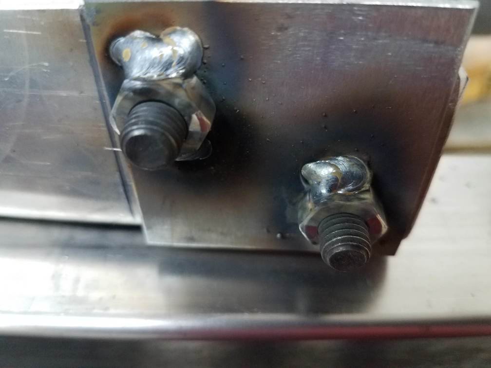
Confirmed 7/16-20 threads on seatbelts. -
Seat Bracket for Kirkey/Jegs/Butler/Ultra Shield type
JMortensen replied to JMortensen's topic in Fabrication / Welding
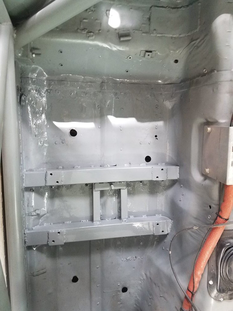
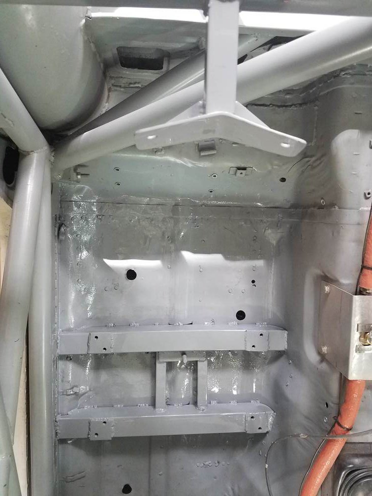
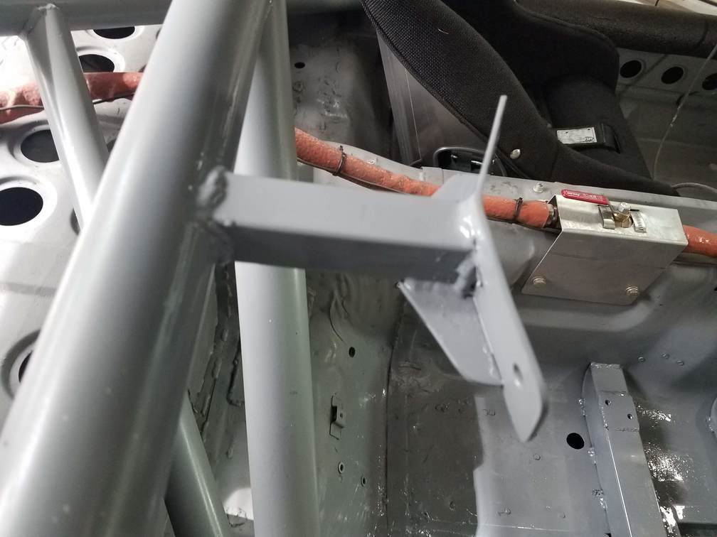
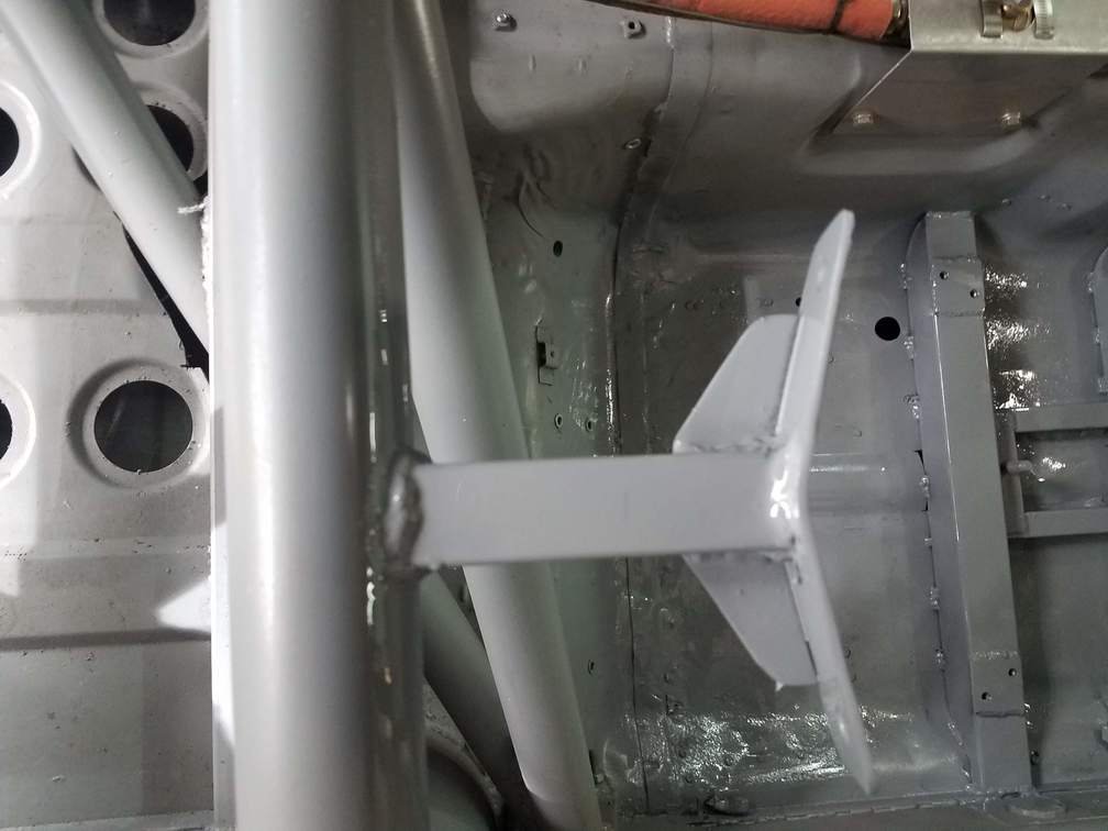
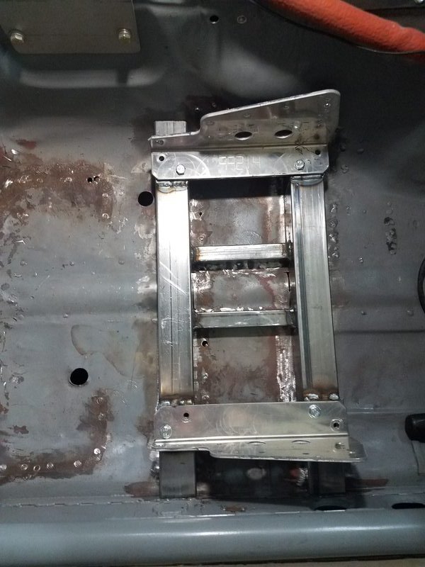
All done and painted. As soon as it dries I'll put the seat in permanently. Anyone happen to know if the seatbelt holes are 7/16-20? I think they all are, but when I tried putting a bolt in there it wouldn't go. Could just be paint on the threads but wanted to verify before I ran a tap through them.
-
Seat Bracket for Kirkey/Jegs/Butler/Ultra Shield type
JMortensen replied to JMortensen's topic in Fabrication / Welding
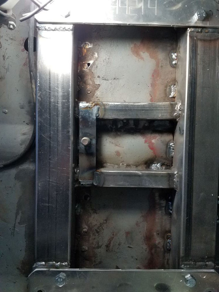
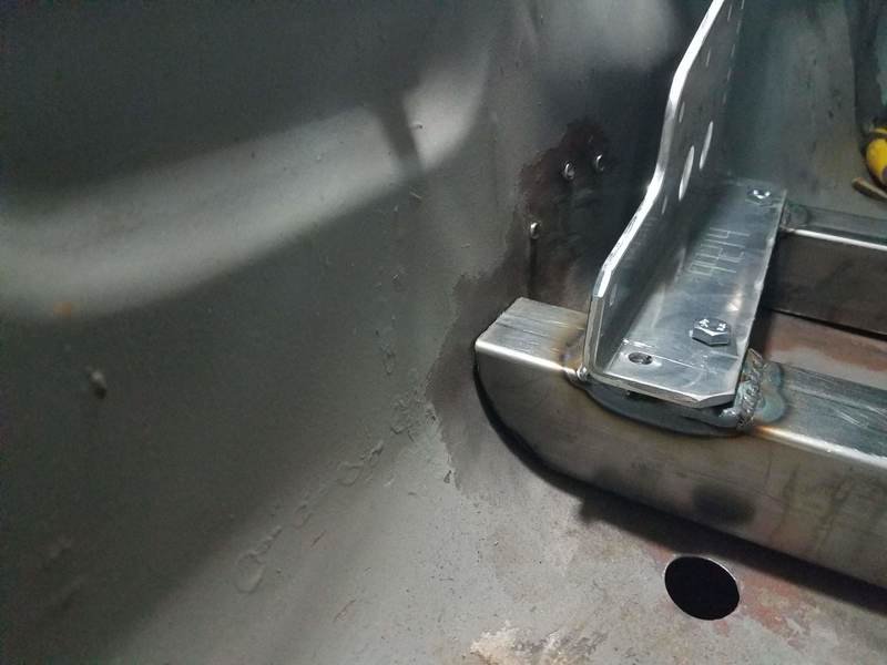
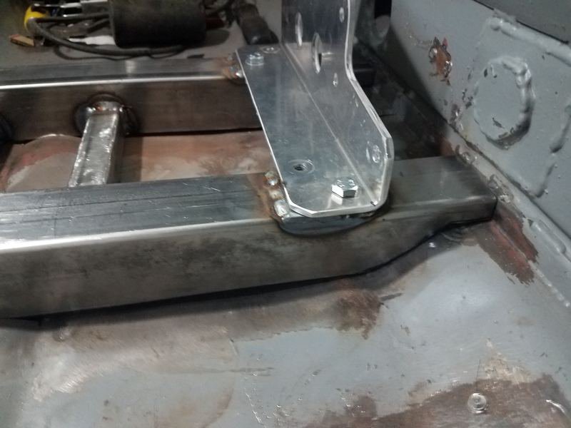
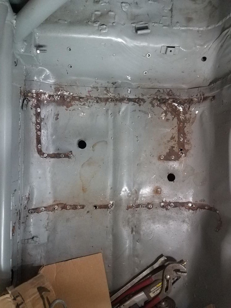
Welding went pretty smoothly. One tip I'll pass along is don't try to beat the floor up against the subframe connecters. What worked much better was a jack with a piece of plywood. Just jacked the floor up to the mount and tacked it in. Had to jack the floor on both sides of the SFC. Then took the plywood and jack out and stitched it. Got in and I'm thinking that the seat is slightly turned towards the driver's side but not enough that I want to redo anything. Also because of the layback there is less footroom on pass side, which might be a good thing as it will make it easier for people to jam their feet against the floor to keep from flopping around over there. Tomorrow: Seat back brace.
-
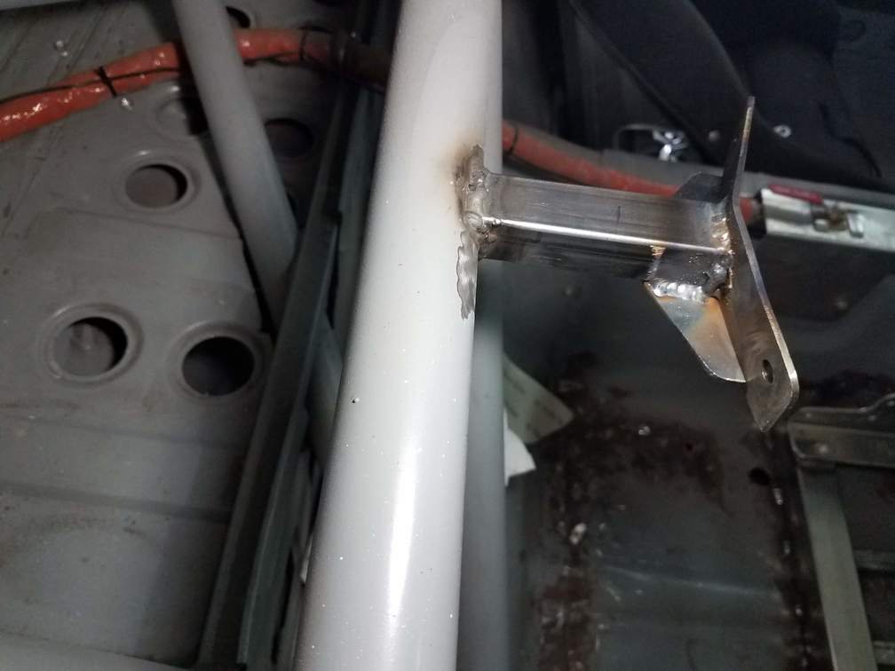
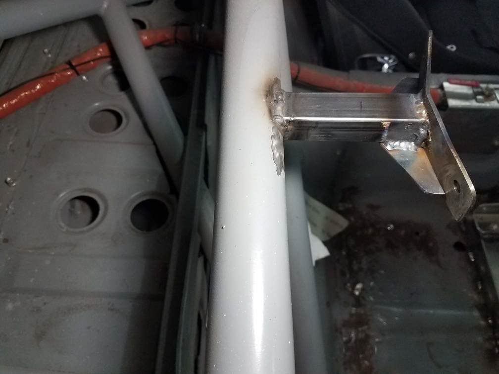
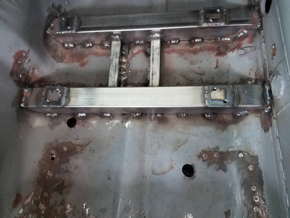
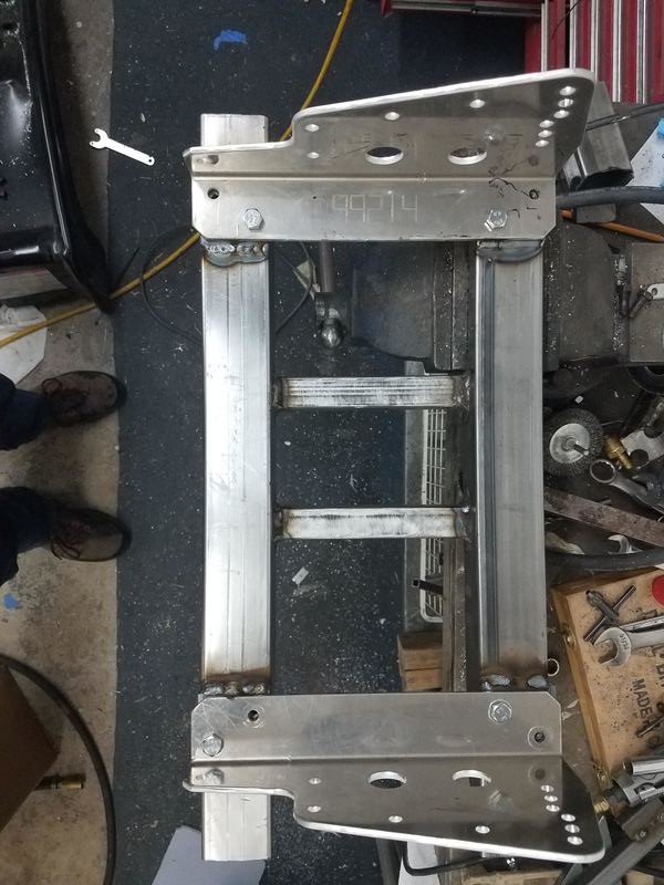
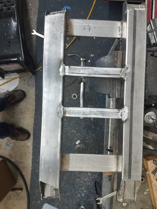
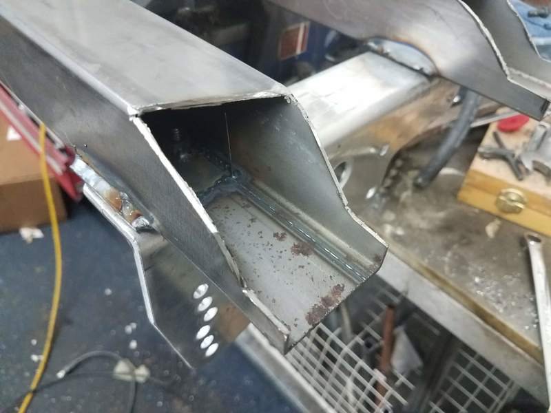
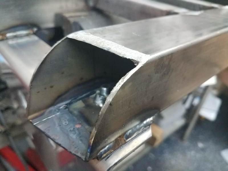
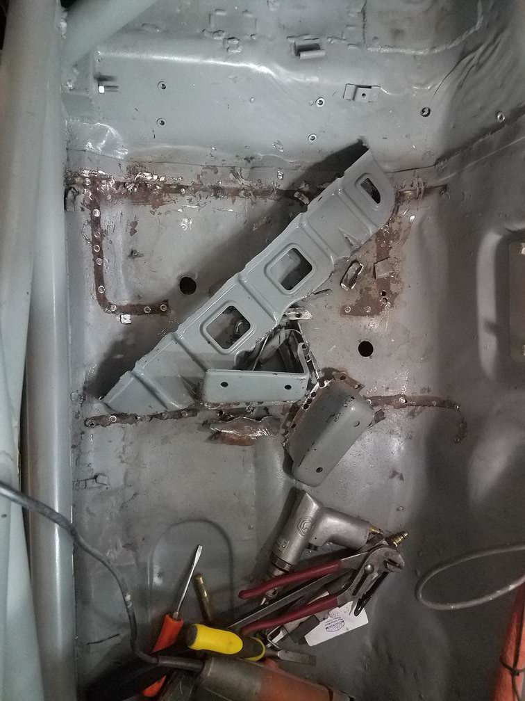
I am working on putting a passenger seat in my race car. Driver's side is on a slider and the mount on that side is totally different but thought I'd share how this non-adjustable pass side is going in. First thing was removal of the stock mount. I had done this on the driver's side 10 years ago or so and remembered it being a big PITA. I did not remember wrong. I really hate trying to get all the spot welds loose. I tried a spot weld cutter and ruined it after successfully cutting about 10 spot welds. Unfortunately there are a lot more than 10 spot welds holding the stock mounts in. After that I tried air saws and other tools, but finally ended up with the tool I hate (and use) the most: 4.5" angle grinder. I used a cutoff wheel and hacked the stock mounts out and ground down as much of what was left as I could. Pro tip: I had been using ear plugs but figured out I could use my new bluetooth over ear headphones to listen to music and podcasts, and I could hear my phone ringing and customers on my website chatting with me, etc. Huge upgrade. I cut the stock mounts out and stuck the seat on the brackets in the car to figure out where the seat mount would be fore/aft. Then I measured from the seam in the floor behind the seats to where the seat bracket would be. I drew a line on the floor where the rear of the rear mount tube would be, and another one 2" in front of that. I had already figured out that there was going to be 6 1/8" between the front and back tubes, so I measured another 6 1/8" and drew another line across and another one 2" in front of that. So now I've got 4 lines across the floor marking where the front and back of each tube would be. Then I cut long strips of 2" tall cardboard, and trimmed them to match the contour of the floor. I then traced them onto the 2x2 tubes and used an angle grinder with cutoff wheel to shape the ends of the tube. Getting the front and back templates lined up correctly is kind of a pain because the trans tunnel isn't straight, so line them up on the outside where they hit the rocker. and leave a little extra on and then grind to fit. On the driver's side I cut into the bottom of the mount tubes to clear the little hump in the middle of the floor. On this side I cut the hump in the floor. I think cutting the hump is easier. After the tubes were cut to shape and fit reasonably close to the contour of the floor, I welded in two 6 1/8" tubes to connect the two and spaced them to fit right where the subframe connectors are. Next I needed to locate the seat laterally. I put the mount in the car and set the seat on its brackets on top of the mount, and figured out where I wanted the seat, then drew lines on either side of the brackets. Knowing where the nuts needed to be to bolt the seat in, I cut square holes in the top of the tube. Then I cut 2 x 2 pieces of .100" sheet and welded nuts to them to bolt the seat brackets to. After that I bolted the 2x2 plates with nuts to the seat brackets and set them on top of the mount and tack welded them in place. I unbolted the seat and brackets and finished welding the plates in. Next I'll weld the top ends of the tube to the rocker and the trans tunnel. I'll stitch the two longitudinal tubes to the subframe connectors. I used a LOT of heat on the driver's side and melted through the floor to get good penetration into the SFCs. My floor was pretty bashed up when I got this car, so the floor doesn't fit perfectly on the bottom of the 2x2 tubing. Plan there is to beat the floor up to the tubing after the mounts are welded on the ends, then stitch across the front and back of the tubing to attach the tubes to the floor. That's today's project. The mount on the driver's side was as long as the slider for the seat, so more like 12". Like I said before, much different on that side.
-
Ford Super 8.8 irs swap thread. Rear brakes too
JMortensen replied to Invincibleextremes's topic in Drivetrain
Second on Dutchman. Best axle supplier I used when I was making stuff. It was done right, first time. -
You can't get around the limitation of a 1.250" stub axle no matter what CVs you use. IMO you're never going to keep the stub axles from breaking at that power level. Time for backhalf or an IRS solution that allows for larger diameter stub axles. I'd look to an 8.8 if you want IRS. Might as well upgrade that too while you're in there. The diffs are cheap and readily available, lockers and limited slips galore, wide range of gear ratios, there are very strong CV options for them, etc.
-
You can specify the site in your google search this way: whatever you are searching for site:forums.hybridz.org
-
Tokico Illumina Strut Failure
JMortensen replied to jgkurz's topic in Brakes, Wheels, Suspension and Chassis
Is Tokico still in business? I thought they were, but they aren't offering these for Z's anymore. Might see if they can fix it. I remember a lifetime warranty when I bought mine in the 90s -
Not sure why you'd want inboard brakes on a 9" rear end, but looks like this guy pretty much has the rest covered: I think that car is the best that I've seen. I love it. There are a couple things I would change, but not many. I do like what I did with my own with the 15x14 wheels and slicks, but I'm sure he would smoke me on an autox course and road course wouldn't even be close as he's got an extra couple hundred hp on my L33 truck engine which should put out ~350whp.
-
Thoughts on T3 'Rear Power Braces'?
JMortensen replied to artishard116's topic in Brakes, Wheels, Suspension and Chassis
To be fair, I have read of some people losing the control arm bushings on a hard launch. Seems to me Jeromio did that about 15 years ago and posted here, and there might have been another one. I'm not going to go looking for it now though. The point, for me, anyway, is that if the bolts are tight, the tube in the control arm already does this job. IIRC the way that happened to him is that the bolts came loose and the control arm slid out of the bushings under hard accel. -
Thoughts on T3 'Rear Power Braces'?
JMortensen replied to artishard116's topic in Brakes, Wheels, Suspension and Chassis
Ok then. Obviously had that wrong. Seems like it's not necessary so long as you keep the big ass bolts on the control arms tight. Probably have to sand down the bushings so that you can actually bottom the bolts out. Hardly anyone does that though. -
Thoughts on T3 'Rear Power Braces'?
JMortensen replied to artishard116's topic in Brakes, Wheels, Suspension and Chassis
If I'm looking at it right, this goes between the lower control arms in the back, connecting the bushings. There is a piece for that in the stock suspension. Looked at their site, and it appears that they use a different brace mounted higher, which would allow for the use of a finned cover with a bigger sump. I guess you could use this piece and their other brace together? Not sure that would really improve anything. I dunno. The more I'm looking at it the more I'm not sure what it is. Can't figure out why you would want the brace up higher and this one too, since they both do the same thing. -
Thoughts on T3 'Rear Power Braces'?
JMortensen replied to artishard116's topic in Brakes, Wheels, Suspension and Chassis
One thing occurs to me. If they slotted the holes on both sides, you could adjust the toe with this. You'd need to pry the arms instead of using a turnbuckle like the Poor Man's Toe Adjuster that many of us have made, but that's not such a big deal if you're doing an alignment every couple years. -
Thoughts on T3 'Rear Power Braces'?
JMortensen replied to artishard116's topic in Brakes, Wheels, Suspension and Chassis
There is already a link there that ties those points together. This one looks cooler, but I think that's the only benefit. -
I would suggest that you consider what you're going to want for camber and work from there. If you want more neg camber than plates will get you, then I'd make the LCAs at least as wide as the stock ones at full compression. With this setup you'd have 5/8" adjustability before you fell afoul of the 1.5x rule. I can't really tell you what plates and stock LCAs will get for max neg camber. I suppose it depends on your ride height. I don't think you can go farther than about 2.5 degrees (would be good to have someone else verify that), so if you are running newer radial slicks or Dot R tires you might need more camber to make them happy. Bias slicks don't need much camber by comparison. Also keep in mind that there is not a lot of thread engagement in the tie rods, so if you add a bunch of width there you'll need to deal with those too. That's easier now as there are aftermarket ones available.
-
Front Suspension Swap? Anybody done one
JMortensen replied to rabrooks's topic in Brakes, Wheels, Suspension and Chassis
The scrub radius issue is a problem. I've got ridiculously wide 15x14 wheels on the front of mine. Had to use spacers to clear the bumpsteer spacers on the tie rod. Car has about 6" scrub, which is a lot. I did this after talking to Tony Woodward of the custom steering rack company and he told me that it really wasn't that big a deal and he had seen plenty of fast cars with 6" scrub or more. I think his experience was more to do with circle track though. You would want the camber plate as far in as you could manage to minimize scrub. The imaginary line from the top of the plate and the ball joint and through the tire contact patch is where the scrub radius is measured from. It's the distance from that intersection with the ground and the center of the tire. Tube80z was looking at a dual LCA system to work with the strut to alleviate the scrub issue on this thread: He kinda stalled out on that and I don't have software to figure it out, but that's an option if you have the software or know someone who can help you out with that. Otherwise, I think SLA is the best solution and you can solve other issues while you're in there, like adding more camber gain, fixing bumpsteer, using 5 lug hubs and bigger brakes, etc. -
Front Suspension Swap? Anybody done one
JMortensen replied to rabrooks's topic in Brakes, Wheels, Suspension and Chassis
Looks like I saw a year old post there. Oh well. Probably missed caperix but might help someone else down the line... -
Front Suspension Swap? Anybody done one
JMortensen replied to rabrooks's topic in Brakes, Wheels, Suspension and Chassis
This is incorrect. Many of us have held this erroneous opinion at one point, including myself. BlueovalZ explained it to me maybe 15 years ago: the control arm doesn't need to be level to start losing camber, it needs to be perpendicular to the strut before it starts losing camber. This is basically impossible, unless you're running really tall tires and trying to scrape the frame on the ground. 24" wheels or something ridiculous would be required to get there. There is a really good thread (IMO best thread on this site) started by Tom Holt and with lots of info from Dan McGrath, aka 74_5.0L_Z, where he takes on all the suspension kinematics. The Z has a very flat camber curve. It just doesn't have enough gain to offset the roll with soft springs. Here is the post where he diagrams the camber curve: