NewZed
Members-
Posts
6700 -
Joined
-
Last visited
-
Days Won
72
Content Type
Profiles
Forums
Blogs
Events
Gallery
Downloads
Store
Everything posted by NewZed
-
-
Did the engine run right before, and this problem came up out of nowhere, on a perfectly right-running engine? Or is this a problem that happened after some recent work?
-
Looks like it cocked at an angle front-to-back. Have you had the transmission cross-member up under the tailshaft? The mounting holes for the transmission mount will be way off if it is.
-
An engine that starts at the touch of the key is just one of those simple pleasures.
-
Well, some do and some don't then. Just offering a consideration, for the OP's own due diligence. Search the web and you'll find many posts about Aeromotive regulators leaking down. Actually, many posts about most of the regulators that look like the Aeromotive style. Probably knockoffs. I think it's just a poor design. A cast aluminum housing, with lots of holes drilled in it for distortion causing fixtures, with a big steel ball in a diaphragm controlling flow. The seat area is left as-cast. Designed for high flow according to Aeromotive's descriptions. Maybe the higher end regulators get more finish work. Mine was the low end model, #13301. I actually sent an e-mail to Aeromotive back in 3/2011 and had an exchange that indicated they were going to address the leak-down in their instructions and in their FAQ section on the web page. It never happened. Copied below, with the name of the tech removed. He was a nice guy, and probably got over-ruled by marketing (I'm a cynic). Just one of those interesting things. Edit - Figured I might as well pile on with a few links. At the bottom. Q: “I recently installed an Aeromotive EFI regulator and when I turn the key to off, and my engine stops running, the fuel pressure immediately falls to zero. With the stock regulator this did not happen, is there something wrong with my new Aeromotive regulator?” A: The stock EFI regulator was engineered with a mandate to hold fuel pressure for 30-minutes after engine shut-down. This is an government regulation with which new car manufacturers must comply. Unfortunately, the mechanism used to hold fuel pressure when the engine is off, has a derogatory affect on a high-flow, adjustable regulator’s ability to create and control fuel pressure when the engine is on. Aeromotive places fuel system performance when the engine is running, particularly running under high load, at the top of the priority board. Anything, such as a checking mechanism in the regulator valve, which compromises fuel flow and pressure control under high-load engine operation, is therefore eliminated. We believe this no-compromise approach to fuel system performance is one of the reasons Aeromotive fuel pressure regulators are universally preferred by enthusiasts and racing professionals alike, around the world. And here is the proposed text for the installation instructions: Note: Aeromotive EFI regulators are fully optimized for ideal fuel flow and pressure control during actual engine operation. Do no be alarmed if your Aeromotive, high-flow, adjustable regulator does not hold fuel pressure when the fuel pump/engine are turned off. This is normal behavior and in fact permits the use of a proper regulator-valve design which delivers superior performance when the engine is running! Just a few.... http://www.dsmtuners.com/forums/bolt-tech/431671-opened-up-my-aeromotive-afpr-today.html http://www.rx7club.com/3rd-generation-specific-1993-2002-16/aeromotive-fuel-pressure-regulator-765888/ http://www.supramania.com/forums/showthread.php?175670-Aeromotive-FPR-dropping-pressure http://www.ca.dsm.org/forums/ubbthreads.php?ubb=showflat&Number=379543#Post379543
-
The OP should take a marketing class before he gets out of college. Or texis300 should. This is a classic violation of product marketing principles. Tease, frustrate, alienate. It's not wrong, and it's not right, it's just how people work. This scenario is typical in bigger business - texis300 is the business manager who wants to show progress, wfritts is the engineeer with the product that's not ready but folds to pressure to release it. The customer complains, the engineer gets a poor review, ends up quitting or gets fired. The idea is panned as "it didn't work". A great idea dies on the vine. Actually, wfritts should take a Masters level marketing class and use this thread as a case study. Probably get an A. Not criticizing, just an impartial observation. Kind of amusing.
-
Following your thread just for the complication of the problem... Browsing around for other views on COP I came across another (one of billions) Megasquirt page that seems informative. They make an interesting statement about dwell control and "over-dwelling" (my term). The coils discharge to save themselves. Considering your blown fuses and the fact that you have too many sparks, it might be worth consideration. The statement and the link are below. A simple test might be to turn the dwell setting way down to no-spark, then bump it up. You'll either get controllable correct spark or be right back to where you are. I would do this with the new coils anyway, if it turns out you've burned the ones you're using. "Note that some coils have a built-in overdwell protection feature. If given too much dwell the coil will automatically spark. This can give a dangerous advanced spark. Be sure to strobe your timing at high revs to ensure this is not happening." http://www.msextra.com/doc/general/sparkout.html
-
Whatever you end up getting, take it apart and clean it out before installing. They can be gritty inside, even new.
-
Could be that you don't have a "toe" problem, but some other problem. If you take your car to a shop and say " I have a toe-in problem, please measure and confirm", many shops will do exactly what you tell them and report what you asked and no more. In this case - "Toe is okay.". Post a picture of the tire at least. Maybe someone will recognize a possibility. Add some numbers, like the what the shop's actually measured. Are they just eye-balling it? Their numbers should be more precise than a piece of string. Here's a decent reference for alignment terms, just to be sure the terminology is correct - http://www.tirerack.com/tires/tiretech/techpage.jsp?techid=4
-
Please help identify these diferrentials
NewZed replied to yuthh's topic in S30 Series - 240z, 260z, 280z
One of them is labeled 3.55. Probably 3.54, depends on your rounding method. Common ratios are 3.36, 3.54, 3.7 and 3.9. Look for more numbers. Or, mark the flanges, spin, and count. -
Describe one of your typical 1000 HP engine so that people have a point of reference. Brand (GM, Ford, Mopar...), model, type of work done, turbo, nitrous, etc. "We run a dyno shop and pop out 1000 HP engines on a regular basis" doesn't tell anyone anything about what you know. You could just be full of BS.
-
Please help identify these diferrentials
NewZed replied to yuthh's topic in S30 Series - 240z, 260z, 280z
Looks like two long-nose R200's at least, and a good match for AkRev's Supra diff on the odd one. The R200's will fit a Z. The Supra diff looks interesting, considering the work that people do to fabricate CV shafts and mounting hardware for the shortnose R200's anyway. I wonder if the Supra diffs are any easier to find than the 300ZX clutch types. The Supra's a clutch type I assume, since it requires LSD oil. It has short side flanges, which should fit inside the transverse links ( control arms) better than the big VLSD flanges. -
differential mount weight plate???
NewZed replied to whatnow123's topic in S30 Series - 240z, 260z, 280z
I use mine as a convenient portable anvil, or weight. I also used one to dress a grinding disc down to a smaller size. -
Please help identify these diferrentials
NewZed replied to yuthh's topic in S30 Series - 240z, 260z, 280z
Can you unwrap them all completely and take more pictures? The first one is different-looking. They all seem to have the general R200 shape. -
The key to the majority of brake problems - if you can pump up the brake pressure there's air in the system. Pumping compresses the air bubbles. It may not be the only problem, but it's one that needs to be addressed.
-
differential mount weight plate???
NewZed replied to whatnow123's topic in S30 Series - 240z, 260z, 280z
It's shown in the FSM. Labeled too. -
Building rear suspension support and need dimensions.
NewZed replied to ChickenCoupe's topic in S30 Series - 240z, 260z, 280z
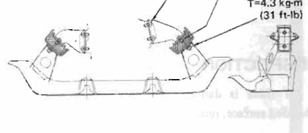
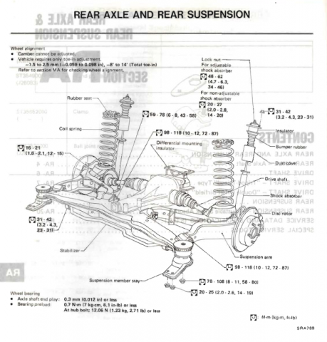
Pretty sure that the only "new" part that you need, in addition to the mustache bar, is the brace between the #5's. Which is not shown in your picture (you can just see the edge of it though). It has more curvature to fit around the bigger R200 diff. Rear transverse link mount might be the name. http://www.zhome.com/ZCMnL/tech/R200.htm This one's bigger than you need but shows the piece. http://forums.hybridz.org/topic/97134-steel-brace-for-clsd-r200-finned-cover-use-in-s30-zcar/page-5 http://forums.hybridz.org/topic/98295-steel-brace-for-r200-clsd-finned-cover-in-s30-new-list-and-design/ -
Need pointers for removing Z31 4-bolt axles
NewZed replied to RebekahsZ's topic in Z31 Series - 300ZX
If they're not turbo cars they'll probably have 3x2 hole axles. Might be easier to just drop the whole sub-frame, drag it out and go to work. -
Pretty sure that "dwell" is an ignition coil charging term. If you're running fuel only you wouldn't worry about it. If you're planning to control ignition and asking for that then, somewhere out there on the interweb, and in Hoffman and Cramer's book there's talk of the finger test method. Increase it until the ignition modules get warm, then dial it back a bit. Or there's math yu can do with your coil's specs.
-
How about adding resistors? Doesn't Megasquirt do both high or low? Why not go low?
-
This company has been around for a while and seems to have a good reputation. Send them a message. http://www.fuelinjector.citymaker.com/requestform.html
-
I had an ignition module go bad to where it produced a weak orange spark that wouldn't start the engine without starting fluid. Once it started it seemed fine (although I didn't drive it), but it would not even pop without the fluid. Worth a shot,maybe. Mine was a GM HEI module, not Pertronix. Installed a new module and I was back to normal.
-
The probably do. Weld the shock absorbers so they don't move and stiffness probably goes up even more. Plus they keep the front end down for drag-racing. We might be starting a trend back to 280Z bumpers, for stiffness! I knew there was a reason to like my old bench bumpers.
-
I don't see the cracked in two on the old greasy box. The links belwo might give you some ideas on front case/bellhousing swaps. Since the end product is basically in 71B form except for length, you might be fine with just a 71B transmission. The output shaft is the same. You just need to check driveshaft length. Or, since your old one already has the 71B front on the 71C back, it might be an easy swap, Bearing hole, clearance and shifter hole are already done. Weird that Nissan was already doing the swap. Maybe that's where the idea came from. http://www.motortopia.com/cars/1973-datsun-240z-11118/car-pictures/240sx-transmission-swap-14041/DSC04293JPG_Thumbnail1.jpg-266482 http://home.comcast.net/~zheimsothtn/transmission.htm
-
Seems reasonable. Although, the heavier bumpers don't make the body stiffer. They were added for other reasons. Side impact crash improvements can add weight with little affect on stiffness. If boxed seat mounts in a 78 adds stiffness it seems like boxing a 76's seat mounts would be worth doing. Or even the early pre-75 S30's. Makes for interesting discussion. Worth considering.


