NewZed
-
Posts
6700 -
Joined
-
Last visited
-
Days Won
72
Content Type
Profiles
Forums
Blogs
Events
Gallery
Downloads
Store
Everything posted by NewZed
-
Could somebody review this please? I can't idle past 200
NewZed replied to Watson's topic in MegaSquirt
I know little about tuning Megasquirt, the 200 RPM just jumped out at me. By the way, I think that only people with Megasquirt or the right program can read your file. Might be limiting your audience. I don't have a program for MSQ files. I saw your thread on the new trigger. Pretty ingenious, I did something similar with an LED and a BA9 light socket (not really so difficult) . But the common cheap LEDs may not hold up to automotive use, even if yours is reading correctly now. I fried one with a nine volt battery and no resistor, it smelled like melted plastic. The lens was made of epoxy. The diode material is one piece of the package, the lens material is another. -
Leaking oil pressure sender
NewZed replied to RebekahsZ's topic in Gen III & IV Chevy V8Z Tech Board
He has a GM engine with a Nissan sender, opposite to the usual problem. So, the Nissan sender is BSPT, and the block is NPT. Seems like some thread sealant would do the job. Loctite makes some. http://www.henkelna.com/adhesives/thread-sealant-thread-sealing-loctite-anaerobics-14405.htm I'd use PTFE tape myself, but that makes many nervous who might lose track of the little thready tape pieces when they take things apart. -
Could somebody review this please? I can't idle past 200
NewZed replied to Watson's topic in MegaSquirt
I'm not positive but I think that 200 RPM is about impossible unless you have a massive flywheel to keep things spinning. If the engine runs but shows 200 RPM, I would think that there's a problem with your tach signal or a setting is wrong. Is the 200 on the car's tach or Megasquirt's and do they match? Do you have some other way to measure RPM? Might be a clue. Just a guess. I can't imagine a stock L6 idling at 200 RPM, but I could be wrong. -
Clean the connections to your EFI harness. And the ignition system. The ignition module might be failing also, with a weak spark, which would be weaker at low voltage during starting.
-
Do you have the dimensions? There was thread not too long ago about replacing the bushing in the 71B transmission. A non-Nissan replacement was found that would work, with a little fine-tuning.
-
Rebuilding Driveshaft for T5 with R200 in a Series 1 240Z
NewZed replied to SuperSamuri's topic in Drivetrain
The PO created a solid diff mount when he welded your old one (Post 3). You have a solid steel path from the gears to the cabin. Get an RT style mount, with the Energy Suspension urethane and the whine noise will drop dramatically. You'll need another crossmember, even if you go back to stock. They're not too hard to find. -
Here's a local (to me) CL listing - http://portland.craigslist.org/wsc/pts/4376551715.html
-
It's easy. Just get good quality FI-rated hose. Make sure the barbs are smooth and burr-free so you don't damage the inner lining, dip the hose end in gasoline and press it on by hand. There are write-ups with pictures out there on the interweb. Just search injector hose replacement. It's even described in the FSM, believe it or not. It's a repair item. Page EF-63 and -64 in the 1976 manual. You can use a knife to cut the rubber off, instead of a soldering iron, if you're very careful.
-
The case study in Cramer and Hoffmann;s Performance Fuel Injection Systems book is informative, Page 142 specifically. It could probably be read in less than an hour.
-
Here's the commonly used write-up on swapping the ignitor with an HEI module. The HEI module will respond to the signal from the ECU like it does the signal from the VR in an NA engine's distributor, apparently. The main difference would be that the HEI module and ECU would be competing for dwell control. It seems to work though. http://www.zcar.com/forum/10-70-83-tech-discussion-forum/285085-hei-ignition-control-module-swap-info-turbos-only.html
-
Sounds like the hot start / heat soak problem. The injectors and/or fuel rail get hot and fuel metering gets screwed up. It's a fairly common problem. The low oil pressure is probably from the low RPM idle.
-
Need help with wheel bearings and stub axle.
NewZed replied to egzlilgituarboy9's topic in Drivetrain
Everything he needs is in the the picture you posted in #16. Where to look for the mark, what the dimension for the hub should be and where to measure from, and the dimensions of the matching "distance piece". Illustrated, with arrows. There's even enough information in the chart to have a new one made, if he has the means to measure the hub width. Maybe he's on a phone... -
Re Post #15 - I quoted what you said, but interpreted what was said differently. The MS igniton control algorithm calculates ahead to control dwell and advance. All it needs is to know where the crankshaft is in its rotation. The page linked below, about using the Pertronix Ignitor in a locked distributor, probably describes it best. This is said often, but the Megamanual and DIY information is scattered, poorly organized, misleading, full of holes and just really hard to figure out. Even the page I link here, labeled as a Pertronix-oriented page, is really just about using the VR input to use a locked distributor to control ignition timing. From the page "When you do this, the PerTronix functions as a sensor for the MegaSquirt, with the MegaSquirt firing the coil." Pertronix is a tiny piece of it, just another sensor, and the page label is probably putting off many people that could use the information, with other sensors to the VR input. It all boils down to getting a consistent solid signal in to MS that lets it know where the crankshaft is positioned. http://www.diyautotune.com/tech_articles/using_megasquirt_with_pertronix_ignitor.htm
-
The passage from the Megamanual that you might be referring to is not really clearly written. What they're saying is that MS needs a signal that is locked to crank position. That's what locking the advance mechanisms in the distributor does. The part about controlling off of the coil terminal is about injection control only, not ignition. With a locked distributor feeding a signal to MS that is locked to crank position, you can do ignition timing control. When the Megamanual guys say "tach signal" they just mean the signal that MS is using to know crankshaft speed. "MegaSquirt-II™ controllers can be triggered from the negative terminal of the coil, just like MS-I, as long as MS-II™ is not being used to control the ignition timing. However, if you are controlling the ignition timing, then the tach signal must be fixed with respect to the crank position (not vary with the advance timing like the coil signal)."
-
It means you're using batch mode for injection, and a single coil for spark. The distributor is getting the spark to the right plugs. Your distributor's VR is being used by MS. Your setup is one level up from the simplest. You're going to spend hours on the forum asking one question at a time. There's really no way around reading on the DIYAutotune and Megamanual sites. Or Cramer and Hoffmann have written a nice book on the fundamentals of electronic engine management. Not that spendy. http://www.amazon.com/Performance-Fuel-Injection-Systems-HP1557/dp/1557885575
-
I don't think that air causes pulling. One of the principles of hydraulics is equal pressure everywhere. The bubble can be on one side, compressing, but the pressure on both sides will be the same.
-
Blue (atlanticz) has pictures of everything. #3. http://www.classiczcars.com/forums/wheels-tires-brakes-s30/46506-reaction-disk.html
-
Open the Megamanual link, click "V3 Assembly", use "CTRL-F" to open a text search box (if you're using Windows), type "TSEL" in to the box and see where it takes you. Looks like you're set up for the VR sensor that is used in the distributor you asked about. You'll have to look around a little more to see if you want your VR input to be inverted. 52. Select the tach input circuit with jumpers: For the VR sensor: Jumper VRIN to TACHSELECT on the bottom side of the PCB (near the DB37, opposite the heat sink.) Jumper TSEL to VROUT (Or VROUTINV if you want the VR input to be inverted) on the bottom side of the PCB, near the center. OR (Do NOT install both sets of jumpers, chose one set or the other!) For the Hall sensor, optical sensor, coil negative terminal or points: Jumper XG1 to XG2 on the bottom side of the PCB, near the 40 pin socket, Jumper OPTOIN to TACHSELECT on the bottom side of the PCB, near the DB37 connector, opposite the heat sink. Jumper TSEL to OPTOOUT on the bottom side of the PCB, near the center.
-
It just gets better... You need to at least put some minutes in if you're going to ask someone else to do some work for you. A better description than the "little connector in the middle" would be a great place to start. Find the numbers on the circuit board or use Photoshop to draw a circle.
-
Astounding. Incredible. Amazing. Something new will always come along. Gobsmacked. This might help - http://www.megamanual.com/index.html
-
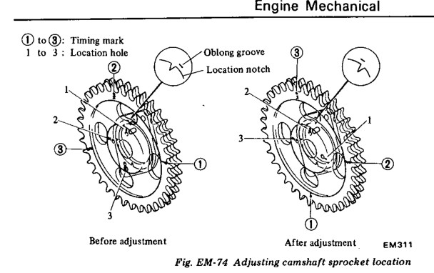
TimZ makes a good point about modified parts. I almost posted something about whether or not that cam is factory or a regrind, if it's a regrind the mark may be irrelevant. But if it's a stock cam the marks should still be aligned, even if they're not optimum. The mark tells you what position the valves are in (since they're at the ends of the lobes), in relation to the pistons. The before and after picture in the FSM is 4 degrees. You're cam is about 8 - 10 degrees advanced. Looking back to your Tuning with Vacuum Gauge post I wonder if you don't have some bent valves. It's like a super bad permanent miss. Or that's just how an engine runs when the cam is way off-time. Could also explain your high pressure numbers, although those measurements are gauge dependent (I get 185 with my gauge on a stock 78 engine) . I think Tony D was on the trail with his comment about adjusting the valves, and starting with a basic full tune-up. Pistons and valves opening and closing at the correct times and to the proper distances is the heart of the combustion cycle. You need to find square one and try to get there if you can. Checking the cam timing is a great starting point, but now you have to fix it.
-
I was referring to the picture in the book. As the chain wears the notch (in the sprocket) lags the oblong groove (bolted to the cam tower). The valves open later. In the picture, "before adjustment" shows a stretched chain (valves opening late), "after adjustment" shows it repositioned so that the valves open sooner. Your notch has the valves opening waaayyy sooner. IF the tight side of the chain is tight. You can also think of it as the straight side. It's the side of the chain that gets pulled when the crankshaft is turning. It needs to be tight to know what is actually happening when the engine is running. The distributor has nothing to do with what you're looking at. It and the oil pump are in a whole separate world.

-
A new player. Had not heard of them. Not much on the web site, not even the typical "About" page. it looks like a Hungarian guy (customer service in two languages) named Jason is selling kits. Looks like there's a guy named Rob in the UK also. Anyway, back to choosing, for the OP....
-
Before you go further, make sure the tight side of the chain (driver's side) is actually tight. If you're moving the crankshaft back and forth, you could have the tight side loose. Set the pulley mark at zero and use a wrench on the sprocket bolt to tighten it up, without moving the crankshaft. If it is tight, then it looks likes someone was anticipating a lot of chain wear. You're in the after-after adjustment zone. Pretty sure I've seen where guys have advanced the sprocket and cam to the 2 hole to move the power curve to the low end. Gives the feel of more power, but the top end is gone. If so, move it to hole 1 and see where things end up. Don't forget to wedge the chain. Nice pictures.
-
Assuming money is no object since you've left it open, this option looks pretty good. Take it to a shop and have it professionally installed. That would be close to the "best" you can do. http://www.electromotive-inc.com/product/total-engine-control/ http://www.electromotivestore.com/engine-management/electromotive-tecgt-ecu.php