NewZed
-
Posts
6700 -
Joined
-
Last visited
-
Days Won
72
Content Type
Profiles
Forums
Blogs
Events
Gallery
Downloads
Store
Everything posted by NewZed
-
Yes, and you don't need anything to do the flange swap. Some people do the seal while the flange is out anyway. You can't do the bearings without taking the whole thing apart. Pages PD-4 and 5 have some good stuff.
-
He implies that he had the CAS in his first post, talking about the 360 slots. Maybe he's unsure of what he actually has. The DIY wheel won't do him much good on a matchbox distributor.
-
I'm no expert at tuning MS, I just know that you should be able to tune around the fuel pressure. I do know a little about data and calculations though and wonder if you're not depending too much on calculated numbers instead of what your eyes, ears, and nose are telling you. According to this link VE is the result of an equation, using MAP and AFR readings as inputs. So with a bad AFR number you can't use VE numbers to tune.. The calculations are only as good as the data used for them. If you're using a separate O2 sensor for MS, maybe it's damaged. Either way, VE is calculated using two variables, either of which could be incorrect. When you're having problems like this you should always check your inputs. http://www.megamanual.com/ms2/tune.htm

-
Maybe it's just a bad AFR meter.
-
That's stated in the reference. And now you're writing in vague terms. Really-bad? We're trying to be specific, I thought. It's a convenience but it shouldn't be causing the complete inability to get his engine running well. To the limit of the limited dynamic range. He's running stock turbo injectors. Kind of raises another question - how rich is rich? He never really said.
-
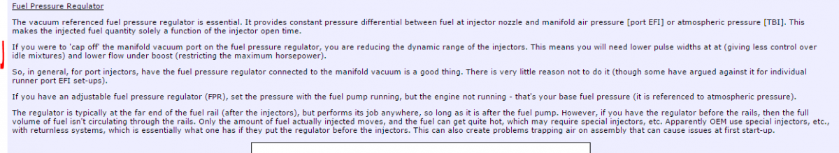
The things that have been suggested are very well known, several to many threads are on this site about any one of them, and easy to check and fix. That's the basic point. This thread is kind of like an engine that we're waiting on to warm up so that it will start running right. And really, we're mainly here for the puzzle, and a reason to go look at old information. Looking back over the whole thing, you have to wonder if it's not just a bad gauge. If you don't have fuel leaking in to the vacuum line, then the only thing that's really the most problematic to work around is the lack of correct pressure correction from the vacuum hose. But even that shouldn't be an issue if you're using a MAP sensor, I think. As long as it's consistent. If it's consistent then you can just change the injector times based on your MAP signal. Circling around to the beginning - is there really a problem here, besides tuning MS? There doesn't seem to be one. One thing you might do is make a table of fuel pressure versus MAP reading and see if it's consistent under a variety of conditions. If it it's not consistent then you'll have problems. If it is then there's really no physical/mechanical problem to be fixed that's going to make tuning easier. You'll be in the same boat with the new parts. Here's a reference about FPR's and MS. They're not essential (he contradicts himself in the text, kind of funny) but they make life easier. But you can tune around the lack of vacuum correction. Way down at the bottom. http://www.megamanual.com/v22manual/minj.htm#fb
-
Never mind, softopz already linked it. That rat's nest of version numbers they have going is incredible...
-
Custom EFI wiring harnesses and pre-configured Mega Squirt systems
NewZed replied to FricFrac's topic in Group Buys
Have you looked through the DIY site? - https://www.diyautotune.com/support/tech/install/ Or the Hybridz threads - http://forums.hybridz.org/forum/93-megasquirt/ If you don't even know how to get power to the harness, you have a very long path ahead of you. You should start your own thread so people can add to it. This is Fric Frac's sale thread. Click "Start New Topic" in the link below and tell people what you're trying to do, describing the car and engine and other details. http://forums.hybridz.org/forum/34-megasquirt/ -
The situation seems more clear now, and we have a new fact, the 19 inches of intake vacuum. That wasn't stated before. If you assume that all of the measured numbers are correct and properly taken, then the FPR alone seems possible as the problem. The FPR is just doing a balancing operation between fuel pressure on one side and air and spring pressure on the other. Seems like the diaphragm would have to be abnormally rigid, stopping the movement of the valve to get the 40 instead of 34.7, like the diaphragm is not reacting to air pressure as it's supposed to. They do get brittle with age, I've taken an old FPR apart and the diaphragm cracked and split in to pieces. Not rubbery at all. So the uncontrollable richness could be from a damaged/split diaphragm letting fuel through the FPR directly in to the manifold. Not uncommon. Removing the hose and looking for liquid fuel in it will tell if the FPR diaphragm is damaged. You can also check pressure leakdown. Watch pressure when the pump is turned off. It should hold at least 20 psi for hours or days. An old brittle cracked diaphragm in the FPR seems to fit all of the facts. By the way, the Aeromotive FPR's leak down immediately when the pump turns off. Very annoying.
-
Here's the link to the sale page, just to round out the thread. https://www.diyautotune.com/product/54-mm-optical-trigger-wheel-for-nissan-l28et-or-vg30e/ If he wired it up to use the six slots and it didn't work, then he probably has a CAS module, or wiring, or MS setup, problem. The DIY wheel just gives better resolution, and a cam trigger for sequential.
-
It's 4 psi higher. Stock is 36. Really not much at all. Modern cars use 3 bar or higher FPR's. 43 psi. You originally asked if the pump might be pumping too much fuel for the return line. Volume increases with voltage for an electric pump. Couldn't find a plot but here's a couple of charts, one at 12, one at 13.5. For the same pressure you can see that output increases. It's the increased output that will cause a backup if your return line is too small, and a pressure increase. http://walbrofuelpumps.com/walbro-f90000267-fuel-pump-e85 Edit - you didn't say that you revved the engine when you measured pressure. Most Z's and ZX's have low voltage at idle. You have to increase RPM to see the max voltage, giving max pump flow, like you would if you were driving, not idling.
-
People seem to be able to get the stock turbo distributor to work. So the trigger wheel is probably not your problem. Not uncommon for the CAS trigger modules to go bad. That seems more likely or the wiring isn't right. Wiring is shown in the link below. You need the pullup resistor to get it right. http://forums.hybridz.org/topic/23244-megasquirtnspark-mssmsns-installation-guide/ It's hard to test the CAS's because they need power (or maybe the harness has its own pullup circuit) from the ECU to work. The CAS module inside is fairly common, people use a later module from cars like Pthfinders if they don't want to buy the whole distributor. https://z31performance.com/forum/z31-basics/how-to-guides-basic/20433-rsb-07-cam-sensor Here's a link about the trigger wheel, although it still won't work if the CAS module is bad or wired wrong. https://www.diyautotune.com/support/tech/hardware/nissan-trigger-disc/ Full disclosure - I'm just writing about stuff I've picked up here and there, although I did swap a CAS module after I destroyed one trying to figure out if it was bad. The swapped one worked fine when I plugged it in to a functional harness and spun the shaft.
-
You've shown that the return lines don't affect pressure at battery voltage. The only way to get a restriction would be at higher voltage, when the alternator is working, making the pump spin faster. You can test that by reconnecting everything properly, then revving the engine enough to max out your voltage readings. If fuel pressure doesn't increase, there's no problem. As far as the 5/16" (8mm) supply lines go, they're the same size as the ZX Turbo supply lines. Overall, it looks like you don't really have a problem with fuel supply, and with Megasquirt you can tune around whatever fuel pressure you set. So you're probably wasting your money on the Aeromotive parts. If you hadn't asked the direct question about your fuel lines somebody probably would have pointed that out. You should be focusing on tuning your Megasquirt. Edit - actually the site's activity levels are way down, and there was an outage a day ago. So your thread isn't really getting much attention. Plus your title isn't very informative. No offense. But an interesting title gets more views.
-
Sorry about that. Couldn't tell why you would even post that link, then ask that question. Good luck with your project.
-
Even the optical distributors just send out a high voltage and a low voltage. DIY and Matt would probably be doing everybody, including themselves, a huge favor by renaming the "VR conditioner" to something more appropriate. The voltages don't have to come from a variable reluctance device. The conditioning circuit may have been designed for a VR device but it works for others. As shown in that article, the voltage doesn't have to drop below zero, which is the characteristic that people commonly associate with VR devices. Positive and negative voltage. That's why it works for other signals though, that only drop to zero or close to zero. I've worked with many engineers though, and most hate to use things for purposes that they weren't designed for, even if they work better than the purpose-built device. There must be an inner war between Matt's inner engineer and his inner businessman whenever he gets in to this topic. Poor guy. If they just called it a "trigger signal conditioner" and showed people how to use it life would be simpler for MS users. Forgot to say also, that there's a circuit labeled "optical" somewhere in MS but it's actually an optical isolation circuit, not an optical trigger circuit. But they labeled it optical and it causes constant confusion. Kind of one of those "pay your dues" things they leave out there, by working your way through the gauntlet of misnomers.
-
The first post in that link describes how you can't just start tearing off ":stuff" without understanding how it works, or how the engine works. The first post in the link is describing your thread here. No offense. You should see that though.
-
You have fuel lines for carbs so you might have the common problem of a too-small return line behind a high volume pump. You seem to have your pressure readings backward, you show pressure higher without vacuum, but that's not how it would work. You can test if the return line is are too small by disconnecting the return line hose after the FPR and running it in to a gas can. See what pressure reads then. If it goes down, then your return lines are causing a pressure increase. The stock FPR should give 36-37 psi.
-
Have you talked to them? Sometimes smart experienced people will not work on things that they're not familiar with. For everybody's benefit. And sometimes shops that specialize get so focused on their thing that they can't see the similarities with other areas. They might not even consider working on a Japanese engine. They look like a fairly typical American metal speed shop.
-
Later ECU's have the computer control timing and the IACV, and they have air regulators to keep the idle high during initial warmup. Read the EFEC chapters of any of the FSM's and they'll describe the functions of the parts. Why work from hunches when you don't have to?
-
Just kidding around. Don't overlook also that idle air and air in the air-fuel mix are not the same. Don't adjust your tables to add "more air" to try and increase idle speed. More air for idle speed is just letting air past the throttle blade. You're really going to have to think deeper to make much progress from here.
-
You could build a fake foot to set on the throttle pedal. OR use a broom handle. Or put the screw valve back on. Or use an electrical valve controlled by the MS you spent all that money on. Many ways.
-
Maybe the stuff you removed wasn't "shit". https://www.diyautotune.com/support/tech/other/idle-tuning-megasquirt/
-
Your title implies that you're looking for a stock furl rail. (I feel like a writing skills teacher). The NA rails will work. Get one of Pallnets. http://forums.hybridz.org/topic/99098-pallnet-fuel-rails/
-
I misread your post, my brain was thinking the car was raised, not the wheel. You're confirming what JMortensen wrote, I think that his thread is the one you're referring to. Still don't know if binding happens on the 280Z or if the 240 and 280 are different. The inner bushings on the transverse link have to compress in a corner. That shortens the distance from flange to flange. Who knows. I wonder what parts contact at full compression in the halfshaft. They should show some wear or damage if binding happens.
-
Did you measure the half-shaft length as droop changed, or the distance between the flanges? The change is not dramatic and the changing angle of the flanges, relative to the axle axis, makes it hard to just eye-ball it. The handling issues are described as happening under somewhat extreme conditions; drag-race type launches and accelerating out of corners in competition. People generally don't notice anything otherwise, when they swap an R200 in to their 240Z, apparently. A couple of measurements and we'd know if there's less space between the flanges or not.