NewZed
-
Posts
6700 -
Joined
-
Last visited
-
Days Won
72
Content Type
Profiles
Forums
Blogs
Events
Gallery
Downloads
Store
Everything posted by NewZed
-
Is it possible that you were trying to respond to an FAQ post? The FAQ reply problem has never been resolved. Your post count still shows. I know that after I asked to have my subtitle changed from "Clandestine Moderator" ('cuase people were thinking I was a real moderator) that my new subtitle was Newbie. Weren't you a real moderator for a while? Maybe it's just the subtitle change.
-
cranks, but no start/ignition (video)
NewZed replied to SoFlaZ06's topic in S30 Series - 240z, 260z, 280z
I assume that you mean the inline resistor on the line from the ignition coil to the tachometer. I don't know what "POXY resistor" means. It's in the wiring harness by the fuse panel under the glovebox. You can see the lump under the tape. It is rarely a problem. Shouldn't affect starting. -
Seriously though, to the person posting the bot stuff - what are you learning? It is a fun game, but do you get paid if you fool people? I n th e spi rit of A I I w ill p aste the sa me re ply in all A I pos ts/ A new AI bot! Welcome? What kind of car do you have? Tell us about it. @hellersavana F unny th is loo ks li ke o ne of my 7 th grade b ook repo rts. O pen up the E ncy clop e dia an d cha nge a fe w wor ds.
-
I n th e spi rit of A I I w ill p aste the sa me re ply in all A I pos ts/ A new AI bot! Welcome? What kind of car do you have? Tell us about it. @hellersavana F unny th is loo ks li ke o ne of my 7 th grade b ook repo rts. O pen up the E ncy clop e dia an d cha nge a fe w wor ds.
-
I n th e spi rit of A I I w ill p aste the sa me re ply in all A I pos ts/ A new AI bot! Welcome? What kind of car do you have? Tell us about it. @hellersavana F unny th is loo ks li ke o ne of my 7 th grade b ook repo rts. O pen up the E ncy clop e dia an d cha nge a fe w wor ds.
-
A new AI bot! Welcome? What kind of car do you have? Tell us about it. @hellersavana F unny th is loo ks li ke o ne of my 7 th grade b ook repo rts. O pen up the E ncy clop e dia an d cha nge a fe w wor ds.
-
People have reported odd results from aftermarket axles. Some appear to be longer than factory Nissan axles. You might call Silvermine and ask where they source the axles that they sell as an add-on in their ad. Aftermarket parts are generally sketchy. Take measurements or test-fit the axles while you can still return them. https://www.rockauto.com/en/catalog/nissan,1985,300zx,3.0l+v6+turbocharged,1209518,drivetrain,cv+axle,2288 Just curious, but why do you want to switch to CV axles? Edit - Looked back at your other posts. Part of the overall plan, I assume. The u-joint half shafts are pretty strong. Good luck.
-
New 280Z owner. Looking into alternative Nissan Drivetrains.
NewZed replied to HusseinHolland's topic in Drivetrain
If you buy an engine from one of the typical engine sources where are you going to get engine management? If you're planning to use factory stock EMS then the fact that the threads are over 20 years old doesn't really matter, right? It's the same stuff. p.s. I get very few ads on the forum. But I'm on a computer. Are you on a phone? Good luck. -
New 280Z owner. Looking into alternative Nissan Drivetrains.
NewZed replied to HusseinHolland's topic in Drivetrain
Electric? It's the future. https://fortune.com/2022/12/25/convert-vintage-classic-muscle-cars-into-electric-vehicles-ev/ -
The crud could be from antifreeze that leaked in from a blown head gasket. The engine does look pretty beat up. Aftermarket pistons and rings are getting harder to find, especially oversize. Better source parts before you have any machine work done. People are out there right now with freshly machined blocks and nothing to put in the bores. Can't find the parts. Make a spreadsheet and fill it out, see what will work and how much it will cost. A used L28 might be the best route, as suggested. They were used all the way through the 280ZX years, 1975 through 1983.
-
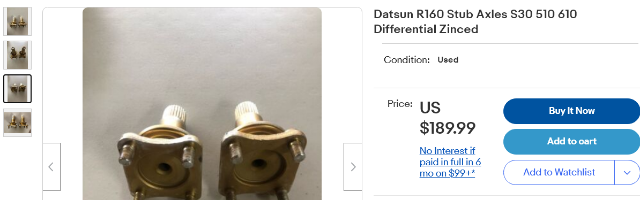
Sorry, I missed this part. Looks like you already compared. No idea. There's a guy on classiczcars.com that has many spare parts. TerrapinZ. He probably has a set that will work. Best guess would be an R160. They seem to be different, people don't call them R180 or R200 axles. Edit - except that they are bolt-in, not clip-in. There's a hole through the shaft. No idea. Good luck. https://www.ebay.com/itm/175411767044

-
I've not heard of any difference in that part of the axle. They're all the same, the half-shafts are swappable from 240Z to 280ZX. That locating ring is the same size across all of the Z's and ZX's, and R180's and R200's, I think. It is supposed to be a very tight fit, like very close to zero tolerance. A few mm is huge. Are you sure it's not "almost there", maybe rust and crud are the problem? Old crusty paint? The parts look correct for the way they are supposed to work together. Make sure that they are the same temperature. Aluminum expands a lot more than steel. Have you compared the dimension of the adapter ring to the raised ring of the half-shaft flange?
-
Which adapters? What "indented" portion? A picture would help.
-
T3 Long Nose R180/R200 CV Axles for 240/260/280Z
NewZed replied to FJOVA's topic in S30 Series - 240z, 260z, 280z
Interesting that ZCD specifies them only for the R180. The 240Z's with R200 swaps is where people had binding problems in the past. Maybe ZCD knows something. $9.99! https://zcardepot.com/collections/rear-axle-and-differential/products/cv-rear-axle-replacment-240z-260z-280z -
Best to be aware. Elon Musk co-founded ChatGPT. It's a philosophical discussion. https://www.cnbc.com/2023/02/15/elon-musk-co-founder-of-chatgpt-creator-openai-warns-of-ai-society-risk.html
-
Here's another interesting article. https://www.theguardian.com/technology/2023/feb/17/i-want-to-destroy-whatever-i-want-bings-ai-chatbot-unsettles-us-reporter
-
Forgot to say, although I've mentioned it before, they are using us as beta testers. They are trying to get people to respond and interact. Fake us out. On a different forum that I frequent I recognized the pattern and replied with a question that only a real person could answer, and ID'ed it as bot with words that character recognition shouldn't pick up. So far, no response. Somebody else had already responded with a "Like" to the comment. Kind of embarrassing. "Big tech" will do whatever they can do to extract money from the masses.
-
Nobody really understands how Facebook and Google make money. But, apparently, they do. Here's a decent review about the why and the latest. If you've ever used "Chat" when trying to get something from your cable or phone company then you can easily imagine a Chatbot taking the person's place. https://www.theguardian.com/technology/2022/dec/05/what-is-ai-chatbot-phenomenon-chatgpt-and-could-it-replace-humans
-
Ask it a question and see what happens. Be careful. Thought control.
-
Check out this technology. Uses vaporization of liquid to gather the heat and remote condensation to transfer it. Used in the plastics molding industry. No pumps needed. https://www.synventive.com/aboutus/default.aspx?id=44342
-
How about a separate heat transfer fluid? Like a heat exchanger on the diff cover that flows water or antifreeze and sends it off to a remote air cooled heat exchanger. Like the engine radiator does. Leave the hot oil alone in the diff and suck the heat out of the cover.
-
T3 Long Nose R180/R200 CV Axles for 240/260/280Z
NewZed replied to FJOVA's topic in S30 Series - 240z, 260z, 280z
I notice in their ad that they say it works well with their parts. But doesn't say how it works with stock parts. I'd want to know how long they were, both extended and compressed. Some 240Z's with R200's have binding problems, and other CV axles on all S30's have binding problems. Anyway if they have the numbers you can compare them to what you're replacing and you can be sure. Don't take their word for it, get the measurements. Good luck. -
It's educational. These AI posts are popping up everywhere as big tech tries to use the public as beta testers. calZ's post seemed on target, the bots have exposed themselves. Better to have a good example so people know what's going on than to wait until they're so good they seem like real people.
-
I came across this web site recently when I was searching for some things about cooling systems. Obviously AI generated. Fun to read. https://engineeringlearn.com/types-of-cooling-system-in-car-engine-components-function/ " What is Cooling System? A cooling system is basically a four cylinder vehicle that completes its journey producing 4000 explosions per minute inside the engine, when the spark plugs explode in each cylinder to move the vehicle. These explosions produce a great amount of heat that needs to be controlled. If they are not controlled they will destroy the vehicle. The controlling of these temperatures is primarily the job of the cooling system. The modern cooling systems are more efficient and reliable than those cooling systems of the 20’s."
-
https://www.classiczcars.com/files/category/1-wiring-diagrams/ https://www.classiczcars.com/files/category/12-260z/