NewZed
-
Posts
6700 -
Joined
-
Last visited
-
Days Won
72
Content Type
Profiles
Forums
Blogs
Events
Gallery
Downloads
Store
Everything posted by NewZed
-
L24 trouble after installing Pertronix Electronic Ignition
NewZed replied to Cbb's topic in Trouble Shooting / General Engine
Did it rev past 3,400 RPM with the points? You've described two different regimes so there's no comparison of old versus new. And why were you idling on the freeway? "on the freeway, my idle would drop to zero, " -
Needing a brake line, driveshaft flange, and door handle.
NewZed replied to mr_han_solo's topic in Parts Wanted
Can't remember (or never knew). I just took an old piece in and matched threads and flare. Pretty sure it's just a simple single flare of some older spec. Most stores have a variety of precut, flared and fitted tube lengths. -
Needing a brake line, driveshaft flange, and door handle.
NewZed replied to mr_han_solo's topic in Parts Wanted
Are there no auto parts stores in Alabama? -
Those washers are actually called "yokes" and they have a certain shape that distributes the clamping force. Some call them thick washers, but thick washers would probably not work correctly. Studs and nuts, or bolts, are used to clamp the yoke to the flanges on the intake and exhaust manifolds. Each yoke clamps two manifolds. The holes are evident between the runners. This won't help much with visualizing but you can get the part numbers. Part #28 is the yoke. http://www.carpartsmanual.com/datsunS30/DatsunZIndex/Engine280Z/ManifoldEgr/FromAug76/tabid/1606/Default.aspx
-
For the record, re the Droid people - Windows XP here (holding out!), with Chrome on an old Compaq desktop. No problems as of now.
-
404 error at 4:21.
-
Seems normal except for slow speed.
-
Testing Reply.
-
Looks like some posts might have got disappeared this morning. Setting a benchmark.
-
The page doesn't reset to the thread being posted to after posting, it just stays on the Reply page. Leading to multiple posts.
-
Thanks.
-
megasquirt ignition on a turbo 280zxt
NewZed replied to br1zzl3's topic in S30 Series - 240z, 260z, 280z
But they don't have to. It's just easier. They shouldn't have called that input option "VR In". It's kind of misleading and limiting. From Post #7 - For a V3.57, you'd have to remove a lot of parts to use the Hall / optical input, so we'll just bring this in through the VR conditioner instead. The problem for many with MS is that you really need to know a little bit about electronics to get through the literature. Or just be a really good reader/comprehender. Even then you have to make some of your own decisions for your own system. Seems like a lot of fun though, from a project building view. The OP never really said what stock system he was using anyway. -
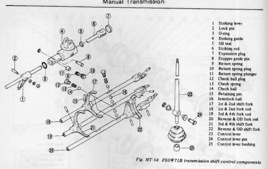
Hope it works out for you. There's a lot of wrong info in their web site copy, like most of the transmission parts shops. http://www.midwesttrans.com/fs5w71.html#partslist Take Advantage of Our Expertise with the FS5W71The FS5W71 is a five speed, RWD or 4WD transmission. The FS5W71 is Peugeot design, split-case aluminum design, This unit has tapered bearings except for the rear mainshaft and rear countershaft bearings. Syncro rings in the FS5W71 are aluminum ring/pin assemblies, the outer plates are part of the forward speed gears. The FS5W71 was used by Nissan in 1974 -1997. Select this link to see what models used this 5 Speed transmission. 240SX Frontier 280SX Pathfinder
-
Those would be the check balls, I believe. For neutral location? I think I figured out at one time that the interlock balls ride on the rods and get pushed in to a location on the adapter plate when the rod moves, locking out the other rod from movement, since there's only room for one ball. Or something like that. It was a puzzle. Anyway, the problem is probably in that area. Could just be that the fluid level is low, or old and gummy, or both. Maybe a fluid change and top-up would help.

-
Heroez has dropped off the face of the Z planet. You should start a new thread.
-
Aren't the interlock balls in the adapter plate what allows only one gear selection at a time? Banging gears, bad lubrication and general use/abuse wears the balls and their locations, apparently. It's one of the things to check and replace when rebuilding a transmission, I think, although I don't know that it's described in the FSM.
-
megasquirt ignition on a turbo 280zxt
NewZed replied to br1zzl3's topic in S30 Series - 240z, 260z, 280z
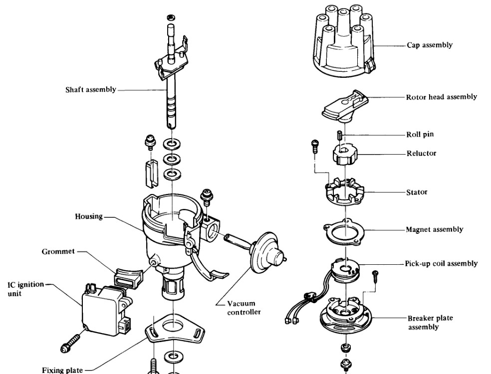
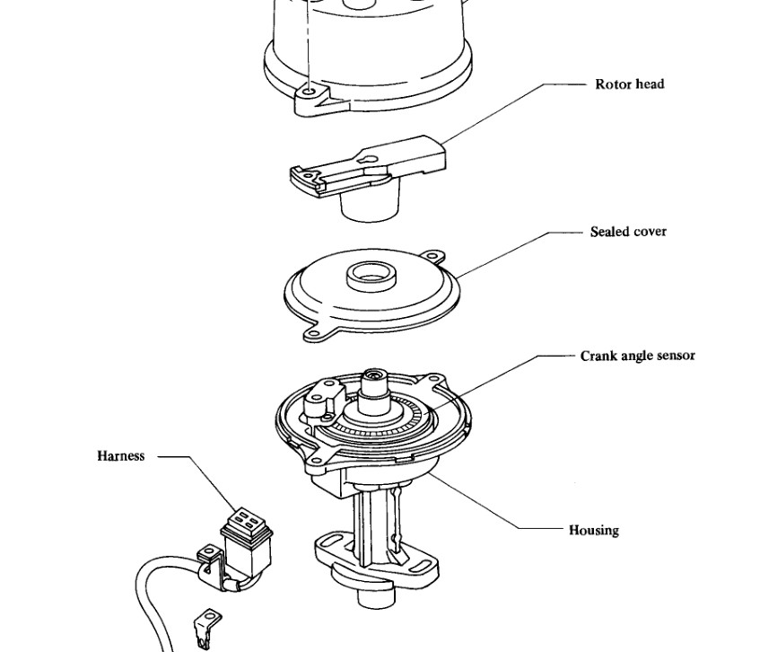
NA is VR. Turbo is optical, LED through slits. Pictures... Here's MS advice - http://www.megamanual.com/ms2/pickups.htm
-
I saved a couple of links about the use of the 25 spline ZX axles in the 240Z struts. You'll have to read through to figure out the details, their focus was on the 4 bolt turbo CV axles. But I think that the 6 bolt (3x2) NA CV axles also use a 25 spline axle, just a different companion flange. http://www.zhome.com/rnt/FordPower/HalfShaft.html http://alteredz.com/240ZCVHalfshaftConversion.htm
-
You're at zero? The picture's at EM-20 in the 1982 book.
-
The MSD 6530 is wired for a MAP sensor. So you can program it for "vacuum" (lower pressure than atmospheric) advance if you buy a MAP sensor and wire it in to the MSD box. Just to tie up a loose end. If you read around the web world you'll find that confusion follows all of the MSD programmable boxes. MSD is like the sterotypical group of engineers, excellent technology just no ability to explain how to actually use it. They must be leaving big money in sales on the table. A simple re-write of their instructions and some better ad copy and they could sell a ton of the programmable units. From a business standpoint it's kind of incredible, that they could see the need, develop the product, then fail to get the word out to potential buyers. And never go back to fix it despite years of feedback. Another downside to the MSD is a MAP failure. Pros and cons. https://www.msdignition.com/forum/showthread.php?t=19572
-
Found this video on John Coffey's new Betamotorsports Facebook page. Shows about how much oil flows through an internally oiled cam while spinning. It's not squirting, just bubbling up like black gold. For those worried about whether they have oil flow or not. Pop the valve cover and spin.
-
It can use one though. For Boost Retard. That's where it's easy to get mixed up. In "absolute" terms, "boost" is anything above zero pressure (literal vacuum). We all live under ~14.5 pounds of boost. Keeping the distributor vacuum advance defeats the purpose of the 123 programmable ignition.
-
No spark from coil to distributor
NewZed replied to Qcsfinest280z's topic in S30 Series - 240z, 260z, 280z
Actually, back to #10 and #11, you should never have 12 volts on the red, if it's disconnected from the module. Are you measuring with the wires disconnected as shown in the FSM? If they're connected to the module when you measure you'll get funky results because you'll also be measuring components inside the module. -
It is possible to seal the leaks in the back of the car so that no fumes can enter. Just to give you hope. A large leak that often gets missed is the vinyl covered trim board on the bottom inside of the hatch. Seal the edges of that piece all the way around (stick-on weather strip from Home Depot works) and any fumes that enter the hatch framework, through the drain holes or the latch mechanism area, will not be able to enter the car. After that the only other seal is around the perimeter of the hatch, the factory weatherstripping. You can usually eye-ball the seal area and see if it's making contact, along with using the dollar bill trick.
-
You're right, that would work assuming the instructions on the MSD site are correct. I've never understood why they don't do a better job of explaining absolute pressure versus atmospheric pressure. It's hard to understand if they really understand what they're selling. How does the MSD unit handle starting timing? MAP pressure will be atmospheric until the engine cranks then will jump to low pressure, advancing timing. Unless the MAP sensor is on ported vacuum. (Actually I see that you covered that in the other thread, with high retard at low RPM). Is the software easy to use? It looks like an option, but you'll still have an old distributor, that you have to modify. So, the 123 option gives you a new ready-to-use distributor for $100, basically. On the other hand, MSD gives MSD, with a stronger spark. Seems like it's down to ease of install with 123 versus a few extra benefits with MSD. A good alternative though. Edit - You can download the MSD software here and try it out, the download is near the bottom of the page, Pro-Data+ software - http://www.msdignition.com/Products/Ignitions/6530_-_MSD_Digital_Programmable_6AL-2.aspx Have to say it's not pleasant. But you do get the satisfaction of solving a difficult problem.