Chickenman
-
Posts
1053 -
Joined
-
Last visited
-
Days Won
9
Content Type
Profiles
Forums
Blogs
Events
Gallery
Downloads
Store
Everything posted by Chickenman
-
There is a debate by some Standalone ECU manufactures on using an engine ground ( Intake manifold or cylinder head preferred ) , or a ground from the ECU straight to the Battery terminal. IMHO, there should be no debate at all. There are dangers associated with grounding an ECU directly to the Negative Battery cable and those dangers should be discussed. The following is why Nissan, and most OEM manufacturers ( that I have ever seen ), always ground the ECU to the engine Cylinder head or Intake manifold. 1: It reduces the potential to create a Large ground loop. Large ground loops can increase electrical noise in the electrical circuit. ECU's and sensor operate on millivolts and they don't like Electrical noise. Andy Wyatt has a good article on proper ECU grounding procedures. It is a very good article. Andy Whittle who makes DIYAutoTuning videos ( very good videos BTW ) , has covered this same subject on Guild of EFI Tuners before. Their consensus is ground ECU to engine.. for a number of reasons. http://www.adaptronic.com.au/ecu-grounding-tips/ 2: The #1 reason for not connecting the ECU ground directly to the Negative battery cable is what if the Main ground cable to the starter is defective or loose??? ... then you can absolutely FRY your ECU in an instant when you crank the engine over. This happens more often than some people realise. A new starter motor draws between 150 to 200 depending on it's Power rating. That's for a small 4 - 6 cylinder engine... under ideal conditions ( Google it ). That's constant running, once they have gotten the engine spinning. On initial start, momentary draw can easily be 250 to 300 amps on a V8 or High compression 6 cylinder. In freezing temperatures that momentary draw can rise to 500 AMPS!!! That's a hell of a lot of current flowing through that Negative battery Terminal. Think about that for a bit. Out main ground strap bolts directly to the engine block. In most cases to the Top starter mounting bolt that goes through the transmission. Thiis connection has to be 100% perfect and be capable of handling up to 500 amps of momentary current. We also have a small 10 gauge wire that goes from the Negative Battery terminal to the Firewall. That handle maybe 40 to 50 amps maximum What happens if you change the starter or transmission and forget to attach the Negative Battery cable to the engine . Or you leave the top bolt a bit loose. Mistakes happen all the time when it's late and you're tired. Or there's a bit of corrosion, dirt, grease, oil , paint or some other contaminant at the ground location for that Neg battery cable. Or perhaps the cable is old and fayed, or has some corrosion in the eyelet? Happens all the time on Vintage cars. What will happen is that when you crank the engine, the starter is going to pull that 200+ amps through any ground circuit it can. If the starter main ground is not PERFECT... that means that it will pull some or ALL of that amperage through ANY other ground source. That includes the tiny #10 gauge wire to the firewall, throttle cables ( Common for them to catch fire as they get so hot ) or any other ground connected to the Negative Battery cable. And that includes your expensive ECU. There is no denying that. It has happened countless times in the Automotive world and is well documented. That my friends is why I always connect my ECU grounds to the engine. You will not fry the ECU if something bad happens to the starter or the ground cable to the starter. And as I've mentioned over and over. Nissan chose the engine grounding method for the ECU fir very sound engineering reasons. I'm not going to second guess them. Or the hundreds of OEM manufacturers who choose the same method. Personally, I have never seen an OEM manufacturer ground an ECU directly to the Battery. Oh I'm sure that somewhere, sometime an OEM has. And I'm sure " Some guy " will have to dig up an example jst to try and prove otherwise. Just my .02c.
-
Matt" Here is the documentation direct from MS Extra showing proper grounding schemes to the Engine Cylinder Head or Block And repeated by other manufacturers. 3.2 Grounding (Earthing) Schemes Implementing a correct grounding scheme is critical to a successful Megasquirt install. Connecting sensors to the wrong ground, using corroded ground points or dubious original wiring are sure-fire ways to give you a headache. There are two key rules: 1. All sensors must ground at the Megasquirt 2. Ground the Megasquirt at the engine block/head using both available ground wires. Reasoning: When a current flows through a wire there is always a voltage drop, the bigger the current, the bigger the drop (this is ohm's law.) During cranking there is a very large current flowing through the ground strap from battery to engine and perhaps a few volts may be dropped across it. Even during running, a number of amps will flow through the Megasquirt grounds to the engine. The sensors (coolant, air temp, throttle position, wideband, tach input) all use low current, low voltage signals. The Megasquirt measures the voltage from the sensor and converts it into a temperature, position etc. reading. If that sensor is grounded to anything other than the Megasquirt itself, then that input voltage will be altered by any external voltage drops. For a sensitive measurement such as AFR (lambda) this can be a real problem. All good wideband controllers offer a high-current ground (connects to engine) and a sensor/signal ground (connects to Megasquirt.) Tach input (e.g. crank, cam sensors) will be even worse - they can show false or missed teeth and cause sync- loss due to the ground voltage difference. The following two diagrams illustrate good and bad wiring schemes showing where the troublesome voltage drops are created and how that would cause sensor readings to be garbage.
-
Matt: Ok now I'm officially confused. Direct grounding of the ECU to the negative Battery terminal goes against recommendations by other Manufacturers and your own information. Voltage impedance from the Starter cranking ( huge amperage draw ) can damage components in the ECU if you connect it directly to the Negative Battery terminal. Especially if you have a bad Chassis ground. And these are 40+ year old cars. And if you have a bad starter ( shorted commutator or excessively high draw ) you can blow sensitive Microelectronics in the ECU. Shane: I thought you said you had grounded the ECU to the Intake Manifold. And the Innovate WB controller to the Intake manifold but in a different point. Was that a Typo about having the ECU grounded to the Chassis? And I thought we went over the issue issues of the secondary ground in the Nissan Optical distributor requiring that the ECU ground be attached to the engine so that you have the smallest ground Loop in the Ignition circuit. Preferably Intake Manifold on our engines. As per factory design
-
You'll never be able to run pump gas with a Turbo and that high of a compression. At least.. not for very long. You may be better off selling that engine and starting all over with a dedicated Turbo build. The Flat Tops cat pistons are a weak point. The Turbo pistons are not only dished but they have much stronger ring lands and thinner rings. Cast Flat Tops, High CR, no knock sensors and Pump Gas is a recipe for disaster. Just not worth it IMHO. That Camshaft is all wrong for a Turbo car as well, and it would be really hard to Turbo the Triple Webers. You are much better off going EFI with ITB's or a Plenum manifold with a 60mm to 70mm TB.
-
Fuel pump and FPR. Not as critical on a NA motor as a Turbo motor. But if you do upgrade to a Higher Volume FP such as a Walpro 255 or Bosch 044, be aware that the stock Nissna FPR cannot properly regulate the Fuel volume put out by a higher performance pump. The Internal return orifice is simply to small. Buy a GOOD quality FPR such nas Aeromotive or Fuel Tech. Both made in USA. Do NOT buy some cheap Chines junk from E-Bay. They are crap and can't maintain accurate fuel pressures. An Aeromotive 13129 EFI regulator is a very good Product. Available from Summit or Jegs. On sale about $130.... and worth every single penny. Don't cheap out on the FPR. You can't get a stable Tune without accurately regulated Fuel Pressure. Also, do not buy Liquid Filled Fuel Pressure gauges. They vary with underhood temperatures. Buy a regular non-liquid filled gauge from Marshal or Stewart Warner. Reda the attched Technical article from Aeromotive on the problems with most Liquid Filled FP Gauges TB_903_Liquid_Filled_Pressure_Gauges_01.pdf
-
Keep the dropping resistors if you get a MS-2 and plan on using the Stock Nissan Low-Impedance resistors. From experience, the the Pulse Width Current Limiting algorithms don't want to play nice with the Stock Nissan Jecs injectors. It works well with most injectors, just not the Nissan Jecs for some strange reason. PWCL in MS-2 can be a bit " Hit or Miss". MS-3 is an entirely different matter. The PWCL works very well in that, but MS-3 uses entirely different Firmware and program coding than MS-2 If you do want to change injectors, I would recommend going to Hi-Impedance injectors. Much less problems as PWCL Get a Pallnet fuel Rail and injectors with 14mm Top and Bottom O-rings. That will give you the most choice in injectors, including most Bosch EV1 or EV6 injectors.
-
Yes, GM does make a Coolant sensor with the same threads as the Nissan one. 12 mm x1.5 I believe. By memory, 99 to 2002 Camaro with the LS motor will work. Same calibration as the 3/8 NPT GM units. Thanks for the Shout out. Steve. Been fairly busy with Tuning lately. .
-
For the Injector blower you could use one of the programmable outputs on MS. They can be configured with and/or functions.. You could configure it to run at Coolant temp >= 180 F, with a hysteresis of 10. Then add RPM of < 250. and seconds = 600. That would turn the Injector fans on for ten minutes when you shut the car off and the Coolant temp is above 180F. You can set the Timer Parameters to whatever you like. ( 300 = 5 Minutes etc )
-
Kool...
-
IAT would be better off in the air intake pipe just before the throttle body. If installed in the Intake manifold it can be subject to heat soak. If you do install it in the Intake manifold you may want to install it with a plastic insert to reduce heat transfer to the IAT body. Madkaw used a Nylon reducer bushing from a Ice making machine to isolate his Intake Manifold mounted IAT. Seems to work well. Home Depot part. $1.25 or something like that...
-
Yes, you can use the stock Coolant sensor. You cam calibrate it as a Custom Thermistor using the figures taken from the FSM. ( Which is online at Xenon ). Or you can use the Calibration for the Saab Bosch sensor in the Tuner Studio pull down menu. The 280ZX Turbo injectors would be perfect, and allow you more than enough extra volume to run a 250 HP NA engine. Yes, the distributor wheel from DIY is what you want. Makes l9ife so much simpler. Be careful when you install it. They can go in upside down, and that will really mess you ( and the ignition settings ) up. Get the Paid version of Tuner Studio. You need the Autotune feature that comes with the Paid version. I you need help with set-up and a baseline tune I do remote tuning for a very reasonable fee. Saves you a lot of headaches. Hybrid member Softopz is a distributor for Mega Squirt and 14Point7 products. BTW, good call on choosing the Spartan WB. Much, much better than Innovate products IMHO. One other thing that you should buy is the MS Tuning manual. Written by Matt Cramer and Jerry Hoffman. Excellent book.!! https://www.diyautotune.com/shop/apparel-merchandise/books/
-
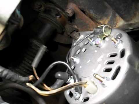
And as I mentioned before. Innovate WB controllers seem to be very sensitive to voltage offsets and electrical noise. ( EMI ) More so than other manufactures. Lots of information collaborating that on numerous forums. The actual design of the WB controller is not up to the standards of other manufacturers I think an alternator change would be a good idea, to solve this particular issue.
-
But adjusting the setting in Tuner Studio is not masking anything. It is a common electrical Calibration that is done with all AFR gauges and auxiliary outputs. The 14 point sevn article explained it in Technical terms. I think you're worrying a bit too much about the " Ca;libration " Many, many industries dealing with electronics or electricity in general have to deal with voltage offsets. It is very very common to see adjustable voltage pots ( or digital voltage regulators on allsorts of electronic boards. The high end car audio industry deals with voltage offsets and ground loops all the time. You should see what an electrical plant has to do with matching frequencies and voltages before tapping into a new Power grid. That's just the way it is. You design your circuit to minimize the voltage offset. With proper ground procedures. That will take care of the big offsets. Then you fine adjust the difference in the software. The alternator issue is a different matter though. It could very well just be old or faulty. A bad rectifier bridge in the alternator will introduce electrical moise into the whole cars electrical system. Worn brushes or a worn commutator. will also create noise. A failing alternator can generate a lot of AC ripple. Which is very bad in a DC circuit. Especially for modern day electronics with digital micro processors that operate on very low voltages ( some operate with millivolts ). Edit: Even a new re-manufactured alternator can put out excessive AC ripple. Depends on how good the electronic components are inside. Rectifier bridge's and Voltage Regulator circuits can be utter pieces of crappola on " Off Shore " made Alternators. It can be a crap shoot.... Come to think of it, didn't you mention that your charging voltage was pretty low.? That is one of a failing alternator. Consider the Maxima 80 Amp internal upgrade. Newer " Small frame " design, that is much more efficient than the old 280zx Internal regulator models. The Maxima alternator can crank out 50 amps at just 1,000 rpm . Just my .02c. Others may have some incite to this as well. Good Luck with your project.
-
Did you see my E-Mail that I sent the other day, regarding the EMI suppression capacitor that must be attached to the +12 V terminal on the alternator? It is to reduce electrical noise. Also, the LC-2 ground must go to the Intake manifold ( In your case ) . You said Body above, but I think that may have been a Typo. Also, the Innovate ground wire has to go to a separate stud on the Intake manifold, not to the same stud as the ECU ground..... for the reason below. Innovate stupidly combines the Heater ground and gauge/sensor ground into one wire. Which is really dumb as the O2 heater wire is a high amperage draw and will can create a Voltage offset. Good manufacturers use a separate ground for the O2 Heater ground and that must be mounted separate from the ECU and regular AFR sensor ground. When you have a proper WB controller with two ground eyelets, the WB controller ground is " Star grounded " to the same point as the ECU ground to decrease voltage offset. Interestingly, the Innovate wiring Loom does have a separate O2 heater ground. Then for some inexplicable reason they spliced them into one wire exiting the Loom. Some people have had success with unwrapping the loom, and soldering on a separate ground wire with eyelet for the O2 heater ground. Other people have reported great success with taking a BFH .... and beating the living S**T out of their Innovate WB controller. Your call...

-
Q's on FricFrac Ms setup and injector impedance
Chickenman replied to Slowpoke's topic in MegaSquirt
Replied by E-mail. -
Q's on FricFrac Ms setup and injector impedance
Chickenman replied to Slowpoke's topic in MegaSquirt
Slowpoke. Check your User Control Panel. Just tried to PM you, but message area is grayed out. Maybe try PM'ing me? -
PM sent...
-
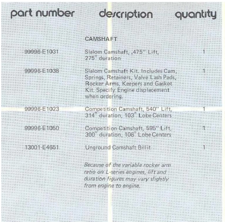
1976 Nissan Comp Catalog. Note Part # 13001-E4651. Big $$$ even in 1976.
-
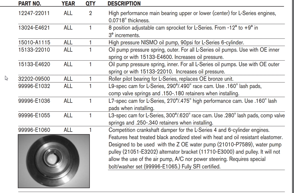
2012 Nissan Motorsports manual:
-
Biggest issue is with a reground Cam, you are " lift limited " by the duration profile. To get more duration at the Nose, you have to grind the Peak or Toe of the Cam. That means you've now reduced the effective " Lift " of the Cam. To get the Lift back, you have to reduce the Base-Circle Diameter or Heel of the cam. You can only go so small with a Base Circle, before you start running into geometry and Valve acceleration issues. Make the Acceleration and Deceleration ramps too aggressive, and you end up with Valve Train instability and short component life. On some re-grinds, they have to " undercut " the core diameter of the Camshaft. That means that they actually reduce the diameter of the Camshaft BETWEEN the Lobes in an effort to get the Base Circle diameter smaller. Of course that can weaken the camshaft core as well. Now, if you start off with an unground new " Billet " camshaft you can get a LOT more lift and duration than a regrinds. Because you have all that extra metal to use on the Profile. It's not unusual to see Datsun L series Race cams ground on a fresh cam Billet having .600" + Valve lift ( 1.54 Rocker ratio ) . That would be impossible on a reground Camshaft.
-
240z coilovers options for racing
Chickenman replied to Marlinfoto's topic in Brakes, Wheels, Suspension and Chassis
^ Techno toy tuning makes some very nice Weld in plates and Camber plates. You won't go wrong choosing TTT. -
280zx ignition module with Megasquirt - is it necessary?
Chickenman replied to supernova_6969's topic in Nissan L6 Forum
With the ground shield it must not be connected to the engine block or Chassis. Only to the inside ECU ground. Having grounds at both ends can induce an offset voltage into the ECU sensor ground circuit. You don't want that. Messes up sensors. I've heard of MS custom builders using a separate box outside of the main MS ECU box for exactly the reasons stated above. To reduce any internal EMI created by the Power transistor ( BIP-373 ). Very good idea with WasteSpark or COP coil drivers that would have multiple BIP373's. The Nissan Module could certainly be triggered and controlled as a Single channel dumb coil driver. That's exactly what it is. Be sure to mount it to a good heat sink though. Those modules get very hot. The distributor body acts as a heat sink from the factory. If not mounted to a heat sink it will fail in short order. The Nissna " Matchbox " module is pretty stout all by itself. You can use an old AMD style CPU Heatsink and fan to keep it cool. Fan may not even be needed. Make sure you use a good thermal conducting compound between the Module backing plate and the Heatsink. -
280zx ignition module with Megasquirt - is it necessary?
Chickenman replied to supernova_6969's topic in Nissan L6 Forum
Advantages to running an external Ignition Module: 1: Ignition modules are noisy electrically ( EMI ) . For that reason, some builders of MS prefer to keep the high current Ignition coil drivers ( BIP373 IGT) outside of the ECU box. Or they build a Faraday cage around the Power Transistors. An external Module, be it a Nissan Matchbox module, aftermarket Ignition amplifier, such as a Bosch or DIY Quadspark unit or even a CDI box, will be isolated outside of the ECU as far as EMI noise is related. Very few manufacturers such as Haltech, Link Adaptronics, or AEM, ever include the High Amperage draw IGT drivers isiden the ECU. They all use external modules to reduce EMI. Logic coil drivers are not the same thing. They are low amperage circuits and don't produce the EMI that the IGT BIP-373 coil drivers Advantages of BIP 373 drivers ( IGT ) 2: The BIP373 drivers are cheap ( $8.50 each ) work well and provide a slightly cleaner install over external modules. We are referring to dumb coil packs of course. Logic coils such as LS2 do not require IGT coil drivers. Cons of external Modules. 1: More cost if one has to be purchased. Can be quite expensive if going more than a single coil. You need at least a 3 Channel coil Module for a 3 Coil Pack Wastespark system. That can be fairly expensive. Although you can sometimes find used 3 Channel Bosch modules for a reasonable price. . Audi V6 and BMW inlne 6's prior to about 2000 had these. 2: Additional wiring. The Nissan matchbox module would have to be re-wired to use the Programmable Timing curve features of the MS. And the distributor would have to be locked out. Not really a Module issue, but rather a choice of distributor type. Cons of Internal coil drivers. IE ( BIP-373 IGT coil drivers ) 1: They produce an ENI field. Nota good thing to have inside an ECU with very sensitive micro-orocessors. 2: They get hot. The more of the BIP-373 drivers you have, the more heat is pumped into the ECU case. Heat is not good for electronics. Worst case scenario for an L-6 would probably be three BIP-373's firing 3 x Waste-Spark " dumb " coil packs. -
280zx ignition module with Megasquirt - is it necessary?
Chickenman replied to supernova_6969's topic in Nissan L6 Forum
Shielding should only be grounded inside the ECU. The other end should never be grounded to anything.... -
I think Issa has a faulty CAS sensor as well. Trigger and Tooth logs are all over the place and intermittent. Car ran great one run, then as I watched in real time, the Tooth logs took a dump and the car died. Trigger logs and Tooth logs were very broken up. Think CAS said.... Buh Bye!!