NewZed
Members-
Posts
6700 -
Joined
-
Last visited
-
Days Won
72
Content Type
Profiles
Forums
Blogs
Events
Gallery
Downloads
Store
Everything posted by NewZed
-
280z still not starting!!!!
NewZed replied to HOLLAATYABOYY1's topic in Trouble Shooting / General Engine
If spark and timing are right, you should be able to get a start with starting fluid and keep it running for a few seconds with a few extra squirts. I think that you mentioned a backfire in the other thread. Are all of the hoses to the intake system intact? Is the oil filler cap on? Is the PCV hose intact? The EFI system does not like to see any air that has not passed through the AFM. It's very important that the intake system and the crankcase are completely sealed. -
280z still not starting!!!!
NewZed replied to HOLLAATYABOYY1's topic in Trouble Shooting / General Engine
Should have kept your other thread going. Now everyone has to ask the same questions over again. You got it to run for a short while using starting fluid before. Why didn't you try starting fluid again? Fuel, spark, and timing are what you need. And air. No offense, but you don't really seem to be thinking about how engines work. You have fuel and spark. And it started once. Why are you testing "power relays" and worried about the air regulator? You have fuel and spark. Have you read the Engine Fuel chapter? Nissan wrote a two-three page tutorial at the beginning on how their system works and what happens during starting. It's a primer on EFI. -
Yes - another Brake Thread. S12W and drums?
NewZed replied to PrincePaul's topic in Brakes, Wheels, Suspension and Chassis
I don't think that I've ever read anyone actually write down what they thought the improvement would be, for any of the various brake "upgrades". Most performance "upgrades" are done for looks, from what I've seen. If you can't describe the performance benefits in words, then you're just doing it for looks. The brake upgrade world typically involves a lot of effort and expense to create new problems. Figure out what you're trying to accomplish first. -
Did you hear bubbles? How long did it run after you used the starting fluid? Seriously, it's not complicated.
-
Setting to stock would be the safest. Valve lash gets tighter as engines warm up, so if you go too tight you can warp/burn a valve. Setting tighter is the "racer's edge" method, with racing edge risk. Could be expensive.
-
electrical Weird Electrical Problem(s)?
NewZed replied to skillinp's topic in Trouble Shooting / General Engine
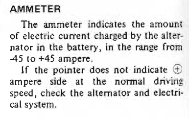
None of what you wrote explains the smoke. Be careful. You have more smoke waiting to come out. I don't know what you're "brushing" your battery terminals with, or what kind of grease you're putting on, but there's a simple $2 tool made specifically for cleaning terminals using hard wire brushes, and no grease is necessary. You can get the took, called a battery terminal cleaner, at any auto parts store, or hardware store, or Harbor Freight. Clean them up, leave the grease off, and clamp them down tightly using a wrench. Check under the dash for wire ends that are brown or burnt. Wire connections get loose or corroded and generate heat. Check the back of the ammeter. -
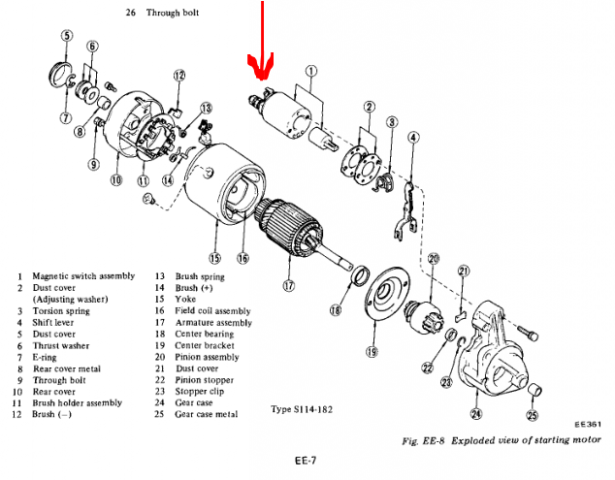
There are several sites out there that have FSM's free for download. Xenonzcar, nicoclub and classiczcars.com. The wire is small and just pulls off by hand.
-
Don't make it complicated. People run out of gas all the time. It might not even be your problem. Run the pump as described elsewhere and listen for bubbles n the tank. When the bubbles stop the lines are full. Then use starting fluid to get it started.
-
The 1976 280Z doesn't have the priming feature. It came on the later year 280ZX's. And often doesn't work, after all of these years. Take the small wire off of the solenoid and turn the key to Start. The pump will run but the engine won't turn over. It's described in the Engine Fuel chapter of the FSM.
-
Nissan says that if you run the tank dry you need to prime the pump. Can't remember where exactly I saw that, either the FSM or the Owners Manual. You might jack the back end of the car up to be sure the pump inlet gets a little help, getting a good fuel supply to start pumping. You can run the pump by itself by disconnecting the starter solenoid wire and turning the key to start. The aftermarket pumps don't seem to have that problem but the stock pump might.
-
Did it run before you bought it? Not much to work on here.
-
You could search the Internet for feedback on any FAST EFI application, I would think, to learn about how it works. zcardepot just put the parts list together to make it east to apply to the L6 engine. FAST has been around for many years. http://www.fuelairspark.com/
-
Richard Oben LS1 series 1 240Z build
NewZed replied to Richard Oben's topic in Gen III & IV Chevy V8Z Tech Board
Did the axles still end up angled or did you get them back to perpendicular to the hubs? -
Pretty sure that I've read a few accounts of sloppy fit for the R200 axles in the OBX diff. Something to consider. The guy that got MFactory to produce a diff apparently put a pretty good product together. Don't know if they're still available or not. Looked better than OBX though.
-
They fit just like the 280Z rails except for the cold start valve (CSV) extension. You can probably bend and/or cut to make it work. I've had a ZX rail on my 280Z engine but I just cut the CSV stem off (no CSV) and sealed it with a compression fitting.
-
electrical Weird Electrical Problem(s)?
NewZed replied to skillinp's topic in Trouble Shooting / General Engine
+ means the alternator is supplying more power than the system is using. That's normal, and good. - means it isn't, that the battery is supplying the power. Apparently, ammeters, or the big wires that supply them, go bad sometimes. They just burn up. http://www.viczcar.com/forum/topic/15680-mysterious-burnt-out-wires-under-dash/ -
Many, maybe all, of the 280ZX axles are actually 25 spline. Nissan did some weird stuff. People use the 280ZX axles to convert their 240Z's to CV axles. 240Z's are 25 spline also. Better count to be sure. http://www.zhome.com/rnt/FordPower/HalfShaft.html
-
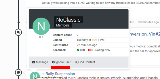
It's just one guy, if you look closely, escalating from a few veiled insults. He doesn't post much except to protect his perception of the past. Just ignore. There's a setting if you want to make it easy. You can ignore me or anyone else. Hover your cursor over their name and a new screen will pop up. Click "ignore" and their posts won't show up when you're signed in. I used yours for an example. Good luck with your car.
-
For Sale: 1970 240Z w/S52 BMW M3 Conversion, Vin#2003
NewZed replied to RTz's topic in Cars for Sale
Do you have a VIN? The collectible 240Z's are going up in price. Might be worth a quick buy for somebody to restore to its 240Z state. -
You shouldn't be trying to use John Coffey's reputation to improve yours. It's just wrong. He would not be doing what you're doing now. If he had strong opinions he just stated them without the snide personal comments that you use. As a moderator he'd probably be shutting you down in this thread. You're comments are not of John Coffey quality, in any way. Try to stand on your own, if you can.
-
Wasn't John Coffey building a rally car?
-
Today's "nano" technology is pretty amazing...
-
Thought that somebody would have had an opinion by now. You never said what clutch setup you're using now so nobody can really choose a "better" one. Nothing to compare to.
-
Beware of the stuff that will vaporize from whatever you're using, when the inside of the car gets really hot. It will redeposit on your windows. You'll be cleaning the windshield every other day if you get the wrong materials. Many paints and caulks and filling compounds use plasticizers to make them soft and/or spreadable.
-
All of this talk about single ground points - engine block, intake manifold, battery negative, etc., whatever - as single points, is pointless. It's the complete circuit that matters. Just be sure that whatever it is that you're powering (and by powering I mean current flow), has a good clean low resistance circuit. It's a circle. If you think in terms of a circuit, then things like your injectors, and the ECU, and your AFR gauge, and your O2 sensors, and your alternator power circuit, and your battery charging circuit (which should be thought of independently of the starter power circuit although the wires might be in the same places), etc., will all make more sense. You can have a fantastic, clean, large gauge wire ground to the intake manifold but if the manifold is not tied well to the block or the alternator of the battery or wherever you decide the current needs to start from and end at, then the perfect excellent contact with the intake manifold won't matter. You have to work out the complete circuit. I think that much confusion is caused by the age-old practice of attaching the alternator power lead to the starter power lug, and the negative cable to the starter close to it. The starter cables are so big that they draw all of the attention.


