cgsheen
-
Posts
676 -
Joined
-
Last visited
-
Days Won
9
Content Type
Profiles
Forums
Blogs
Events
Gallery
Downloads
Store
Everything posted by cgsheen
-
Really Jon? I agree completely with your first sentence. I'll take your word for the first half of the second sentence (and I think "mistafosta" probably does know). I can't agree at all with the latter half of the second sentence. Your third sentence is spot-on. The guys at Stance-USA take racing seriously, are very accommodating when it comes to special projects and custom valving, shock dynoing. I'm very interested to see what they come up with.
-
It's been a while since I bumped this - so, here's a bump...
-
While you're checking the sensors, check the wiring and connectors - clean, clean, clean them, both sides. JavelinZ has a late 280 that he dailies and gets through emissions every year. His is ALL stock though... If you end up needing a mechanic, go see Scott - he's a few doors down from us. 1985 E 5th Street, Suite 10, Tempe. I can get you his phone number but I don't have his card on me right now. He's sorted out a few Z's that we've sent down there - both EFI and carbed. He knows Bosch L-Jetronic - very knowledgeable about vintage imports.
-
Ya. Mine originally came from a pick-n-pull because I was there to "do the Honda blower swap". That's when I discovered the Kia blower. (I actually looked at every import in that yard because I thought the Honda blower looked kind of wimpy...) Mine has worked great lo these many years - but now that I know, I'd just buy a new one rather than go back to the junk yard...
-
Dude... That wasn't a smart-a$$ remark - just a very true observation about many people and their Z cars. Not condesending, not a "put-down", just an observation... I love (no... LOVE!) my L28ET. But my situation was nothing like yours is. My L28ET was given to me by my youngest Son. I had no Z at the time - didn't expect to ever own one. I had to find the frame to put this engine into. I didn't have a Z Car with an engine that I had put a lot of work into. My advise would always be to swap an L28ET - that's my thing. But, I didn't have an engine that I put a lot of work into before this engine appeared in my garage - and thus my advice may mean nothing to you and your situation. Would I personally turbo a "non-turbo" engine? Nope. I'm not that smart. After working on this thing for several years, I've come to find the wisdom that the "old timers" speak of - and I now agree with them. My true enjoyment of this car came when I got the suspension & handling sorted out. Now the power that I add will have something worthy to do.
-
But it's the first thing they always want to do...
-
Isn't there a light bulb in there? (or a light socket...)
-
-
Correct - the stock early Z Car never had a starter relay. The starter "signal" comes straight from the Ignition Switch (Black/Yellow). The addition of a relay is a modification many - if not most - early Z owners have done over the years. It cures a common problem these cars develop as they age. TONS written about this on all the Z Car sites. You can either find the relay and figure out why it's not working, replace it, wire in a new one, or rewire the start signal from the ignition switch to the starter solenoid. A Factory Service Manual may help - you should download one... (OR... Always park on a hill or something with a grade, turn on the ignition, put the trans in 2nd, let it roll down the hill, pop the clutch. At least that's how we did it in the "olden days"... Meh,, who needs a starter )
-
How far down the road is the RB? IDK if I'd go through that much to "get this thing moving" with the parts you have if it's only a short while before the RB is ready... If it's years - maybe.
-
Help with my auto to manual swap
cgsheen replied to Viva Datsun's topic in S30 Series - 240z, 260z, 280z
The pedals are different between the 240 and the 260/280. It has to do with spacing of the master cylinders (with the small booster in the very early Z's, the master cylinders were closer together. They had to change pedal design when they started using a bigger brake booster...) Just make sure you get the correct pedals. The pedal box itself is the same between auto and manual, so only the pedals and their hardware need to be changed. The aluminum plate ( "dust cover" ) between the block and transmission is definately different between manual and auto. The plate is split on the auto to allow access to the flex plate and bolts that hold the torque converter to the flex plate. Get the proper plate for the manual transmission. Take the speedo pinion gear out of the auto trans and use it in your manual trans. It should be the correct gear for your rear-end - unless you're replacing the differential also... When you take the auto out and get the flexplate off, be sure to remove the spacer that's behind the flex plate before you try to mount a flywheel. That's a good time to install you new pilot bushing as well. With the "later" transmission, you may want to get a rubber shift lever boot and steel clamp down "ring" from a 260 / 280. The very early Z's used a different trans and had a different hole and boot configuration in the trans tunnel. You'll need to mimick the later trans tunnel hole and boot for your 5-speed. -
Remove the latch and catch mechanism from the underside of the hood. Set the hood down. How does the hood fit side-to-side? Gaps relatively even? How does the hood fit front-to-back? - What is the gap between the hood rear and the cowl? (normally about 1/8" or so...) - How does the front of the hood mate with the headlight buckets? How is the elevation at the nose? Does it mate with the height of the fenders properly? (personally, I would go so far as to remove the torsion rods as well and check the position of the hood...) Pictures of fitment would help a great deal. Pictures of the hinges would help a great deal. IF the hood sits properly in it's "hole" (without spring or latch), and the gaps are pretty consistant, and it doesn't "poke forward" at the front corners past the headlight buckets while it's sitting relatively even with the fenders in height - then your latching mechanism is wrong. IF the hood (without spring or latch) has too much gap between the hood and cowl, and the front corners poke out farther than the headlight buckets - then it's too far forward and the only adjustment for that will be in the hinges. I'm wondering if you may need different hinges - did they replace those too? The "Nissan Tech" loosened the 3 hinge-to-body bolts on both sides and "adjusted" them - as well as the 2 hinge-to-hood bolts on each side? Worry about the height fitment after you have proper gap and latch.
-
Brakes have me lost...
cgsheen replied to Volition77's topic in Brakes, Wheels, Suspension and Chassis
Try bleeding the master cylinder again. Just like bench bleeding, use 2 short tubes from the bleeders back into the reservoirs and pump the pedal 3 or 4 times. Tighten them back up and check it again. -
If the engine is not running your fuel pressure should be around 36 PSI. When running it'll drop with (by) the amount of vacuum in the intake manifold. (the FPR is supposed to maintain a 36.3 PSI pressure differential between the fuel rail and intake manifold. If you have 10 PSI manifold vacuum, you should see 26 PSI in the rail - if you're boosting 5 PSI, you should see 41 PSI...) You weren't clear about where you were testing spark. At the plug? But, ya, you should check timing. Then make sure you're getting fuel. You can try starting fluid...
-
Did they remove the hinges as well as the hood? There's quite a bit of adjustment there between the mount to the body and the mount to the hood - but it does help to have some experience taking it off and putting it back on. If you're ever on the East side of town, stop by the shop and we'll have a look.
-
I've never had any luck testing the ECU "signal to fire" with the crappy multimeters I use. I never get a voltage reading - it happens too fast - I think you'd need an oscilloscope. "There are two yellow/white wires coming from the computer" - The Yellow/White you're looking for comes from ECU pin 5 and only runs a short way to a connector under the dash in the stock harness. The 1982 280ZX FSM shows the wiring (without colors unfortunately) and how the ECU connectors and pins are laid out in the "Engine Fuel & Emission Control" section: EF&EC-96 . You don't need colors, just match the connector, it's clip, and double check your "orientation" with the missing pins (spaces with no wires) in the diagram... You'll find "pin 5" right away. (outermost two-row clip, pins 1-10 are on the clip side, pin 1 has no wire, pin 3 has no wire, pin 5 is right by the clip, pin 7 has no wire) You can test the CAS, but if you already have a replacement, you may as well swap it out. Be sure to test your components AND the wiring back to the ECU. You can pull the plug out of the distributor and test voltage (with IGN ON) and GND (red and black to the 4-pin plug). Also check continuity of the Green and White wires back to the ECU (they change colors in the ECCS harness) but one goes back to pin 8 and one to pin 17 - use the above diagram. Double check your HEI wiring. It's nearly as simple as the original coil/ignitor. It needs power and GND. It has a signal input from the ECU and an output to the coil "-". Disconnect the stock Blue wire to the coil "-" terminal until you have spark and/or the engine running. Remember that the GND on the HEI is actually the body (and bolt holes). Make sure the Black/White to the "+" coil (and thus the HEI) has power at IGN ON. Check and clean all the connectors in the harness. Most ECCS problems turn out to be electrical - wiring and connectors... Have fun!
-
You have a PM.
-
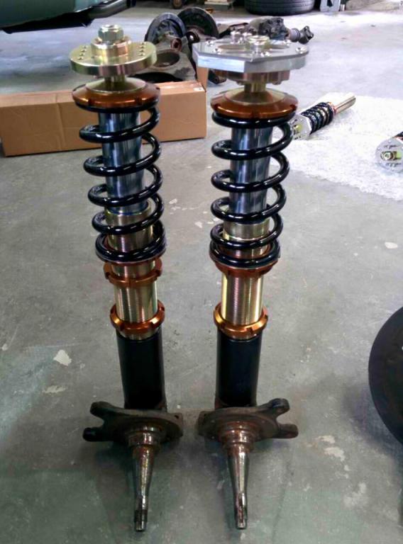
Just wanted to give a "shout-out" to Vintage Spirit Garage. They did an awesome install for a common customer of ours. Here's a couple of pics of the Stance-USA coils and our Sakura Garage Camber Plates being done up by the great guys at Vintage Spirit.

-
To crank the engine and check compression just unplug the start signal wire from the solenoid and use a remote start switch. Search for Bosch and/or L-Jetronic connectors and you'll find more of what you're looking for: http://www.ebay.com/itm/B1-Rectangle-Bosch-Style-3-wire-TPS-Sensor-Connector-Pigtail-With-Rubber-Boot-/331015323139?pt=Motors_Car_Truck_Parts_Accessories&hash=item4d120cfe03&vxp=mtr 90+ percent of the L28E & L28ET problems can probably be traced to wiring and connectors in the ECCS harness. There's a very good troubleshooting guide in the FSM. You can test every (well, nearly) component and sensor with simple tools PLUS their connection back to the ECU. Look for AFM tampering - if someone has opened it up and "adjusted" it you may be fighting an uphill battle... The AFM is the LAST thing that should ever be screwed with and it seems to be the FIRST thing noobs go to. The TPS on an L28ET is nothing close to what we think of as TPS in modern cars. It actually only uses one of the two switches - the "idle" switch - and it merely signals "throttle open" or "throttle closed". It cannot signal actual position otherwise and does not use the WOT switch.
-
Looks like one of the fusable links blew and they wired in another type of fuse. There are a bunch of threads on how to wire up the HEI, just search here or Google it... Get the '82 FSM from http://www.nicoclub.com/FSM/280z/1982/ or at xenons130.com - it might help you understand what this engine needs in order to run properly. I'm with FricFrac though - your time (money, education) would probably be better spent on a different engine management system. I do understand the desire to know how it runs before you swap, but getting it started and running with the stock ECCS may not actually tell you. Normally we spend an inordinate amount of time getting the stock engine management (ECCS) to work like it's supposed to (so the engine will run like it's suposed to...). These L-series engines are pretty hardy though and if they're maintained even half decently, they run for a long time. How does the top of the engine look with the valve cover off?
-
What do you mean "It's losing power"? Do you mean it's actually losing battery voltage (I can't see how that's possible if you wired it straight to the battery...))? OR are you talking about the LED turning off during cranking? If so, that's normal - the LED is NOT an ON/OFF indicator... The FSM covers this behavior.
-
Yup.
-
The stock 280ZXT fuel pump relay is a simple single switch relay. It takes four conections: 1. "Source" voltage to one side of the switch. - - - On the stock '76 280Z: Battery -> Fusable Link -> main power to IGN Switch (tee off this wire for source power to fuel pump relay) 2. "Output" power to Fuel Pump on other side of the switch. Relay -> Green wire to Fuel Pump 3. GND to one side of the relay coil. 4. Blue/Red from ECU to other side of the relay coil. The way this simple relay works, it does matter which side of the "switch" is wired to "source" and which is wired to "output" and the same holds true with the coil - as long as one side is GND and the other is the "control" wire from the ECU. The ECU controls the relay with the L/R wire. So it "turns on" and "turns off" the fuel pump using the relay. The ECU controls the fuel pump for safety. It knows when the engine is turning (C.A.S. signal) and will kill power to the fuel pump when it's not turning. In a collision, ("we don't call them "accidents" anymore" - Hot Fuzz) it keeps the fuel pump from running on and possibly spewing fuel where you don't want to be spewing it... A relay is just an "electric" switch. It "makes" or "breaks" a circuit. The simplest example is having two wires in your hand - touch them together and the circuit is "complete" or "made", remove them from each other and the circuit is broken. The relay has a "coil" which is an electro-magnet. When it is powered, it pulls a bar down that connects two wires together (that's the "switch"). When it is unpowered, it releases the bar and the connection is broken.
-
The 6-pin and 8-pin connectors are "interfaces" with the other harnesses in the ZX. Otherwise the ECCS (engine) harness is pretty self-contained. Some of the "interface wiring" won't be used - they're either for items not present in the early Z, or they're things you won't care about anyway... The important stuff is in that drawing you posted above. Temperature Gauge: You have 2 options... 1. Use the existing wiring, connect it to the new engine's temp sender. If your stock harness is still in place (wiring that came across the core support to the coil and etc.) there will be a Yellow that connected the sender to the gauge on your original engine. Just hook it back up. 2. The ZX put the gauge wiring in the ECCS harness - it was easier to run it that way. SO, they needed to bring that back to the body harness. You can use that Y and tie it back to your gauge wiring at the firewall or under the dash or something. Option #1 is easier if the stock wiring is still there. If you do, just ignore both ends of the Y temp sender wire in the turbo harness. You do need the B/W connected to the other B/W's in your car. There are engine components that need the connection. The Turbo fuel pump relay is the simplest relay possible. The fuel pump relay in the '76 Z is part of the overly-complex EFI relay. If you can figure that out, more power to you... Me, I just use the ZX relay and run the output to the Green power wire for the fuel pump. You'll find it under the glove box (and the harness that runs down to the floor on the right side - running to the back of the car.). You REALLY want the ECU to control the fuel pump so my advise is to ALWAYS wire it up like it's wired in the ZX... Safety first.
-
Power - The 2 wires (Green, Brown) that supply power to the ECCS are normally connected to the Battery through fusable links. Your last picture shows the Green & Brown and their stock white connector. On the ZX, that plugs straight into the fusable link. So, you can cut off the connector (or find a mating connector with wires) and run the G and Br to your fuses. Battery(+) -> Fusable Link -> Green Battery(+) -> Fusable Link -> Brown You can use your maxi-fuse(s) in place of the fusable link(s). (I don't because it confuses me. I just grab the fusable links from the 280ZX. The fusable link is a wire size smaller than the wiring it protects (the thought being: it'll melt before the "protected" wiring does...) I don't think I've ever seen a definative "this is the amperage FUSE you need in this circuit" to replace the fusable links. I know there have been some guesses and some "this is what I used and I haven't had a problem" but I don't know if anyone has studied the amp draw...) Black/White in early Nissan/Datsun's is always "Battery Voltage at IGN ON" . - It originates at the IGN Switch. - There are a few components in the ECCS and/or Coil/Ignitor that need a B/W connection. - All Z Cars have a B/W to the coil area in the stock harness. EDIT: The second 8-pin connector you have in the pictures is for the Fuel Pump Modulator. It shouldn't be cut apart and it can be left UNUSED. If you install the modulator box, you'll need to do additional wiring to the fuel pump. My advice - don't use it... The Blue/Black does NOT provide power to the fuel pump. Wrap everything up so there's no chance of a short. The wire marked "Fuel Pump" in the picture above would normally be a Blue/Red (L/R) AND it would connect to Pin 16 on the ECU (and the ECU socket...) Trace that wire to the socket and see if it's correct. - It is used to set the fuel pump relay (turns the relay on and off) - - It provides power (battery voltage) to one side of the relay coil. The other side of the relay coil is GND. - The stock Fuel Pump itself is wired like this: Battery -> Fuse -> Fuel Pump Relay -> Fuel Pump The other 6-pin "interface" connector you need is on the part of the harness that runs across the firewall to the battery area (with the power wiring, CHTS connector, knock sensor wiring, etc.) That's the connector that'll have the L/R to the fuel pump relay coil, B/W for the IGN ON power, and Y for the temp gauge...