NewZed
-
Posts
6700 -
Joined
-
Last visited
-
Days Won
72
Content Type
Profiles
Forums
Blogs
Events
Gallery
Downloads
Store
Everything posted by NewZed
-
Sensitive Brake Pedal
NewZed replied to compression's topic in Brakes, Wheels, Suspension and Chassis
Probably the "reaction disc" in the booster. A common enough problem that it has an FAQ entry. http://forums.hybridz.org/topic/69706-reaction-disk-pictures-and-walkthrough/ -
I'm not a real MOD. But thanks for the better writing. It looks so much better. This guy might know how to reach him. They live in the same area. Check the second post of this thread. There's a website link in his profile. http://forums.hybridz.org/profile/4498-zachary-ard/ https://store.acadianasportscars.com/ @Zachary Ard
-
There are other people selling fuel rails. If Pallnet is unreachable. Use Google. Doesn't seem like you're putting work in to it besides poorly written posts from your phone. Google...soooo much effort.... @pallnet
-
Changing the master cylinder changes the amount of force required at the pedal to achieve stopping power, and the distance the pedal travels. It's really about pedal feel, not performance, so it's more personal preference than "required". blu didn't really give enough info to answer his question. Post a link to the brakes. Not even sure who "z car garage" is.
-
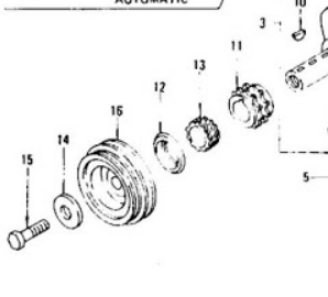
There was a recent thread about damper bolts and red loctite that has some good facts in it. There's no lock washer. The keyway got worn because the damper was loose, not vice-versa. The key isn't meant to hold the damper. It's for locating it's rotational position. The fact that your first damper was loose is a sign that something's wrong, either damaged crank snout or the wrong parts So when you replaced one damper with another you just kept the same damage and/or the same wrong parts. Just with a different damper. It's a simple looking part with a lot of complex engineering behind it. You need to find the directions and follow them exactly. Good luck.

-
Just circling back. Lots of wrong here. "noticed balancer was loose so put a spare on". It's like you got super-lucky but didn't heed the warnings. You said the balancer "broke off". Is there a piece left? Or did it fall off and you were actually running with no belts? Should have at least since the charge light come on, besides the overheating. Not clear how bad this really was. Guessing that a piece broke off, allowing oil to leak past the seal, but the damper and pulley were intact, and the bolt was still in place. A sign that the bolt was not putting force on the damper hub. Probably did a bunch of damage. You might not even be able to get another damper on. They're typically set as light interference fits. Try to fit the old damper and see. If it won't fit, a new one probably won't either. Good luck.
-
You need to do more study on the dampers, bolts and washers. It's not just Loctite and torque. The length of the bolt has to fit the thickness of the damper and the washer underneath and the washer's seat has to be right for the damper. Sounds like you have a mismatched set. theistuation is more comlicated than u ar realizing.
-
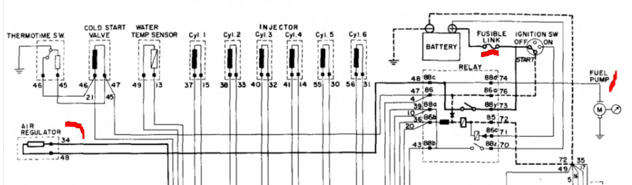
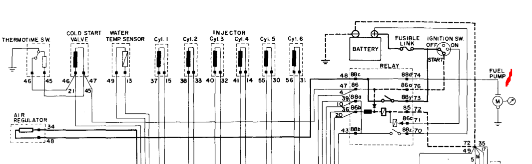
Now that your relays are right, be aware that 1976 uses a fuel pump relay contact switch in the AFM, and a separate Start power circuit. Starting then dying quickly is a common sign of the AFM switch not staying closed, due to low air flow. The engine's intake system, including the crankcase (the PCV system is connected to the intake system), needs to be sealed so that all air entering the engine passes through the AFM. Any leak, like a missing oil fill cap, will cause the AFM vane to stay closed and the switch to open, killing pump power. It's a safety feature.
-
There is an open channel between the windshield and the seal. Water can leak in from one place on the outside and a different place on the inside. Take it for a drive and see if water appears from nowhere and beads up on the inside of the lower corner of the seal when going around a corner. It can also leak through the door by the window and out between the door panel and the door. Run your fingers along the bottom of the door panel and check for wetness.
-
The drive shafts (Nissan calls them propeller shafts) are not the same lengths.
-
2JZGTE swap pulleys..how do I keep AC with power steering delete?
NewZed replied to 280JZFlorida's topic in Toyota L6 Forum
Just a thought, that might actually end up looking good. Cut the back off of a power steering pump and use the front as an idler. If the bearing and pulley are designed to take the load in the front it might even be sound, engineering-wise. Who knows, the back of the pump might even unbolt. Worst case, it provides the measurements for a fabbed-up idler pulley. -
The other things connected to the power source can cause a voltage drop, but they won't cause zero voltage, like you reported the first time at the relay. That has to be a broken circuit. Not sure that the floor temp lamp or sensor would be involved in a zero reading. Your ignition switch tests don't say if you wiggled the wires or the connector, or the key. You said the problem was sporadic, sometimes there, sometimes not. Those are are the worst kinds of problems because you have to reproduce whatever causes the randomness. So you tested once but can't confirm much from that single test. I'm not sure how you're doing your measurements but you might start measuring with the connectors connected. Through the back of the plug. Then if you get a zero at the relay you can go back to the switch and see if it's zero, or the other side of the relay. And don't overlook the connectors themselves. I had a T plug at an alternator that looked fine but was not making electrical contact. I've also had my starter solenoid wire do that (almost bought a new starter but wiggled some wires first). When you get an odd result wiggle connectors while your meter is still connected. Tap the relay to see if the solenoid is stuck. Good luck, I've spent some time figuring things like this out and you have to think outside the box when you're getting weird results.
-
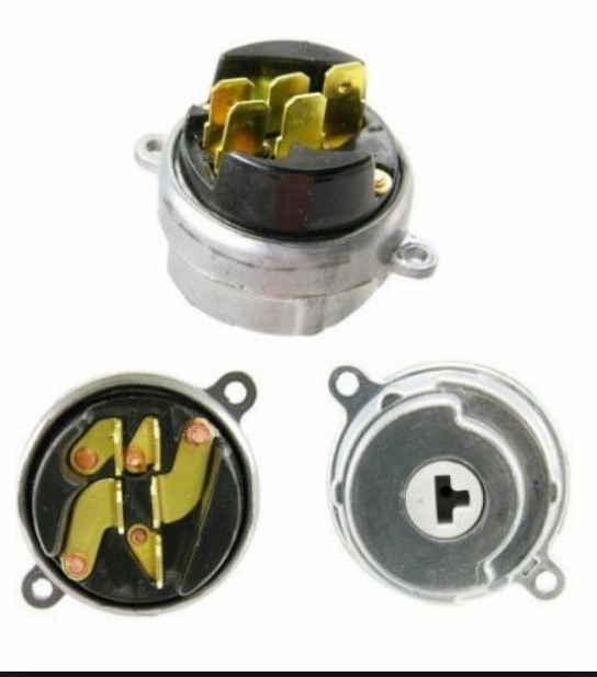
That sounds more like a bad ignition switch. It's not uncommon. Pin 71 gets its power directly from the switch. The pins in the electrical switch can get loose and have sporadic and weak contact. I had one, it was the Start pin, and it took me quite a while to figure out. You might remove the switch and check it, along with its wiring. The hardest part is removing one of the little screws that has a one-way head on it. Theft protection. Here is a link to a very nice color diagram. By a member there called Saridout. https://www.classiczcars.com/files/category/1-wiring-diagrams/ Here's a picture of the part, and its source link. It's behind the key. I had to restake the copper on the back to fix mine. https://zcardepot.com/all-products/electrical/ignition-switch
-
Your continuity tests might be confusing you. Better to measure resistance. And study the wiring diagram. If you look at the diagram I posted before you can see that Pin 34 is the ground circuit for the air regulator. And it's on the same circuit as the power supply for the pump. So if you measure continuity you are measuring back through the air regulator to ground. The pump ground wire is also connected to ground. So they are connected, circuit-wise, but only via a common ground and common power supply. The pump and air regulator are branches on the same circuit. If you measured resistance instead of continuity you'd probably get about 60 ohms,that's about what the air regulator heating element is. If you don't get 60 ohms then you might have a wire that has shorted directly to ground. It might also have destroyed your relay, or blown the fusible link. I would take a few more measurements, check your fusible links, and look for a wire with broken insulation.
-
10 years after hybernation - '75 280z
NewZed replied to tamo3's topic in S30 Series - 240z, 260z, 280z
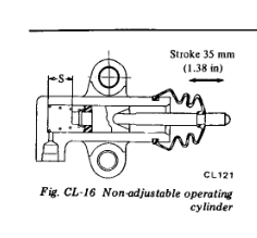
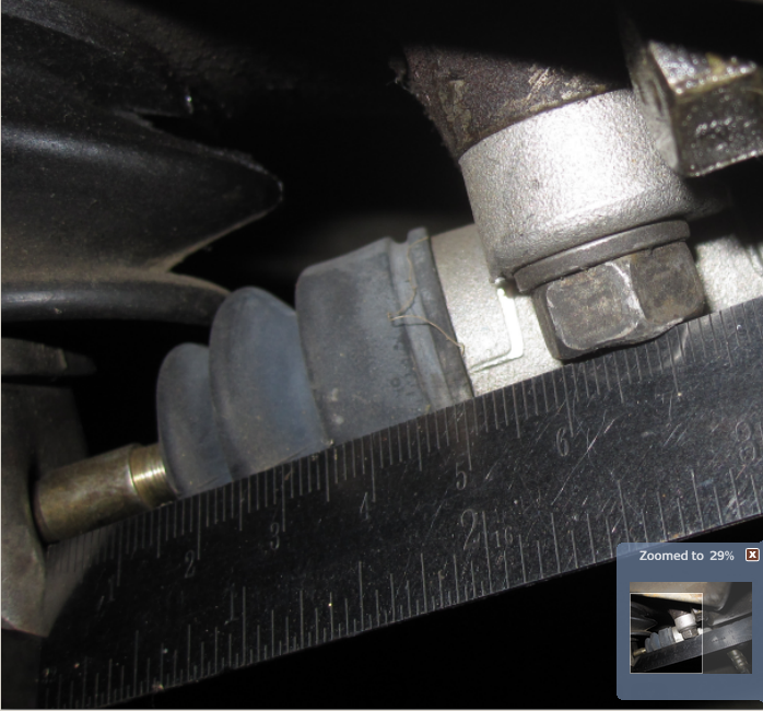
Just went and pushed the rod back. I have lots of room, like you do. It's not at the end of the stroke though, and I have put many miles on it. Apparently, the factory stroke is 35 mm. 1.38".
-
10 years after hybernation - '75 280z
NewZed replied to tamo3's topic in S30 Series - 240z, 260z, 280z
Seems like that should work fine. A few mm there will probably be less than one mm at the TBO due to the ratio of the fork. It's not clear what problem that you're having. I watched your video and see that the piston is far down its stroke. But I don't know what the total stroke length is. Are you saying that when you press the pedal the fork doesn't move? If you were at the the end of the stroke the piston should pop out of the bore. My picture was taken with the pedal up. It was just me, a steel rule, and a camera. I'm going to go out and see if I can push the rod and piston back as far as you do in your video. -
That will stop the pump from running once the engine starts. The engine will start then die, over and over, because there is no air keeping the AFM vane open. But the AFM switch is bypassed during Start, as shown in the wiring diagram. You need that hose to keep the engine running. But, since the hose is off it will be easy to stick a screwdriver in to keep the vane open. This should keep the pump running and allow the engine to stay running if you get it started. But it will only idle and maybe rise a few RPM before it leans out and starts backfiring or dies if you open the throttle. Unless you manipulate the AFM vane by hand at the same time to pretend it's measuring air flow.
-
Since yours is a 1976 model you can also prop open the AFM vane with the key on. Use something inside the AFM or take the black cover off of the side and move the damper weight. That will send power to the pump also.
-
If you measured 9 volts on one of the wires that is about right (actually it's low but it should still run your pump), with the voltage drop from the starter. You tested the pump and it works. That leaves the ground. Edit 2 - rethinking the 9 volts. That's pretty low even with the starter draw. Seems like the battery needs charging before further testing. It's not really clear why you were measuring continuity when all you needed was voltage and ground. If you disconnect the yellow wire at the starter solenoid you can get power to the pump without the engine turning over. The fuel pump will get power at Start but the starter won't. Makes it easier for testing. You can hear the fuel pump.
-
10 years after hybernation - '75 280z
NewZed replied to tamo3's topic in S30 Series - 240z, 260z, 280z
Here is a picture I took a while ago that might help you figure out where your problem is. It's the distance from the clutch fork to the head of one of the slave cylinder mounting bolts, on a properly working clutch system. It should tell you if you have the correct TOB sleeve inside. A short sleeve will measure more than 6 cm, a too-tall one will measure less. This is the starting point, and travel is fine.
-
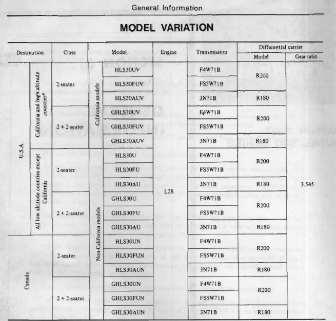
Looks like Nissan used the R180 with the automatic transmission. 3N71B.
-
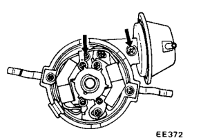
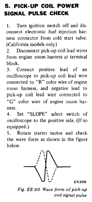
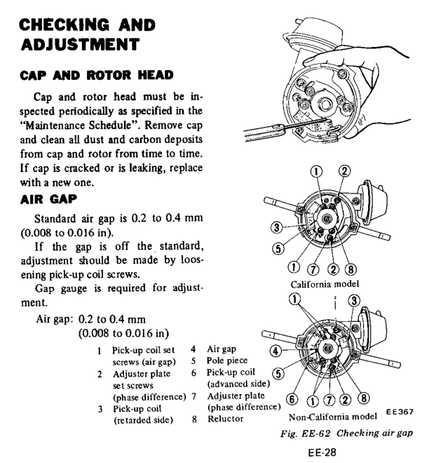
You're almost there. Your test of touching the wires together, which created a spark from the MSD box, shows that the last, missing, piece is the trigger from the pickup coil. You showed that you have a good pickup coil. The trigger voltage from the magnetic pickup is caused by a ferrous piece of metal passing by, the six bladed metal wheel next to the pickup coil. If you have a sensitive meter, or an analog meter, or an oscilloscope, you can see the voltage from the pickup coil when the distributor spins. Nissan even drew a picture of what the voltage looks like on an oscilloscope in the FSM, Engine Electrical chapter. Find a way to see if you're getting that voltage pulse when the engine spins. You haven't confirmed that the distributor shaft spins with the engine, for example. Things slip or break or get put together wrong. People have had the drive gear slip on the shaft. People forget to put the rotor under the cap. If you're testing for spark at the coil main wire take the distributor cap and rotor off and spin the distributor by hand. Or just watch it when you turn the engine over. Or lift the distributor up and spin it by hand with the key on. Lots of possibilities. Focus on the triggering system. One thing that might cause problems is if you have the wires connected backward. Maybe switch the red for the green. Usually it just causes timing problems but maybe the MSD is more sensitive and won't work with a backward waveform. There's also an air gap adjustment that needs to be right to generate voltage. Check that.
-
The test that you did here shows that your MSD wiring was correct. You're just not getting the voltage pulse from your distributor. Your MSD wiring looks right, it's your distributor's magnetic pickup signal that is not getting through. When you touch the green and violet wires together you create a voltage pulse that mimics what the distributor should do. Focus on the distributor.
-
And make sure the distributor is actually turning when the engine turns. You're at the "don't assume anything" point.
-
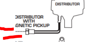
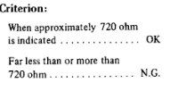
Measure resistance across the wires from the magnetic pickup in the distributor, with them disconnected. You might have the wrong ones connected or have a bad pickup. Should be about 720 ohms. You won't get repeated spark unless the trigger is triggering.