NewZed
Members-
Posts
6700 -
Joined
-
Last visited
-
Days Won
72
Content Type
Profiles
Forums
Blogs
Events
Gallery
Downloads
Store
Everything posted by NewZed
-
The ball valve might not last long with gasoline flowing through it instead of water. Wire nuts are always bad. Weird that somebody would remove fenders to put louvers in that spot. Looks like a Baja rig, but with potential. Can't tell if your pictures are before you got it or after. Good luck. Edit - not trying to be negative. But you have a curiosity there.
-
Assuming that the slave cylinder diameter is the same as the master diameter, which is common, it would be pounds of force on the pedal times the length of the pedal in feet. ft-lb, not ft/lbs. The hydraulics will transmit the pedal's force to the slave cylinder at a 1:1 ratio if the cylinders are the same diameter. If you want more force at the slave, you would use a smaller master cylinder, trading distance for force at the slave cylinder. Short answer - it's probably the same as it is for the L series engine.
-
Not sure what you mean by "straight line". What you're trying to do is to get the crankshaft parallel with the pinion shaft of the diff. They can be offset but have to be parallel. So when you're done the transmission could be pointing to either side or above or below the diff, but as long they're both parallel you'll be okay. Another way to define it is that both joints must have the same angle. Maybe you know it already but here's a good link. The angles are up, down, and sideways. https://www.drivelinesnw.com/part-trouble-shooting/vibration-analysis/angle-analysis/
-
'78 280Z Charging Issues
NewZed replied to TheWeekendWagon's topic in Trouble Shooting / General Engine
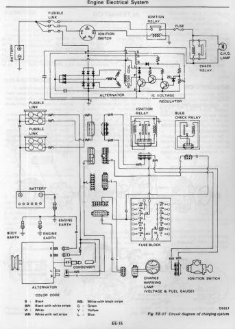
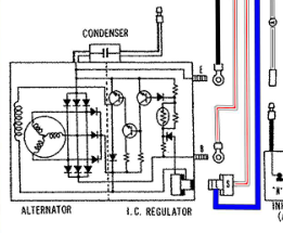
I was going to mention what Sam280Z said about the Charge light. But the diagram shows a parallel circuit with the check relay so that wouldn't be a problem IF the diagram is correct. Current through the check relay solenoid would supply the L circuit and the bulb circuit would not be necessary. Now that you've mentioned all of the other problems, it seems more likely that it could be the cause and the diagram is not correct. Good luck. At least you know that it's power to the L wire that is the problem. -
'78 280Z Charging Issues
NewZed replied to TheWeekendWagon's topic in Trouble Shooting / General Engine
According to one diagram that I have that is the L wire, for Lamp. It supplies power to the alternator windings. That would explain your problem. Now you just have to find out why it doesn't have power. Nissan made things complicated in 1978 with lots of extra relays and gizmos. I think that the best you can do is to follow that wire back. Looks like it gets power through a"check relay" (maybe your e-brake warning light) and also the Charge lamp. The Charge lamp in the meter should light up when the key is on. The colors aren't right in my copy of the 78 FSM but it shows the various connectors. Maybe you just lost a connection. Edit - looks like they only mislabeled the color, WB, right at the plug. It's back to "L" (blue) farther down the circuit. It does indicate a splice to a yellow wire along the way. Nissan used a crimp on to exposed wire to create branches. Likely a stressed point, susceptible to bending and fatigue. -
People say that the welding process itself will often help break a bolt loose. The heat and the current. You can spend a lot of money at a machine shop. Make sure you agree on a maximum price. Sometimes they get obsessed and will take a lot of time to get it out, all at their hourly rate.
-
'78 280Z Charging Issues
NewZed replied to TheWeekendWagon's topic in Trouble Shooting / General Engine
Get a voltmeter and measure voltage at the plug to the back of the alternator. The T plug. They should both show 12 volts with the key on. Also make sure that plug is making good contact with the pins in the alternator. I had a plug that was loose and was not making contact. Had to recrimp it with a pair if pliers. Make sure that the charge wire to the lug on the starter is intact. It's the white wire that starts at the B terminal on the back of the alternator. And check your fusible links. -
The 260Z carbs and manifolds should bolt right up to an L28. People do it all the time, especially when they have problems with EFI. Many L28's don't have the parts or holes in the head for a mechanical fuel pump though, but the 260Z has an electric pump anyway.
-
The rail and FPR don't have anything to do with the pump. Pump noise depends on how it's mounted and how powerful it is. Start your own pump thread and you can get a pretty good conversation going. This thread is Pallnet's vendor thread. Don't want to clutter it up.
-
Use the "Single Fuel Rail Fuel Injected" diagram here. Ignore the others, some aren't quite right. Leave the unused inlets on the FPR blocked. The supply is at one end of your rail and the FPR at the other. Tank-(prefilter maybe)- pump-filter-rail-FPR-tank. https://www.aeromotiveinc.com/in-line-diagrams/
-
That red loctite idea is good for a first try. High strength thread locker. Worst case the nut just comes off and you're left with more grippy threads. Probably pay about $8 for a tube of Loctite. Most of us try to go cheap with the tools at hand. And regret it.
-
I like the red loctite idea. Another option is JB Weld Steel-Stick. If you use either, stick a piece of plastic wrap over the nub, leaving the threads uncovered, so that you don't glue the nut to the head. And clean the threads of any lubricants. MEK or acetone preferred for cleaning. Filing flat is apparently personal preference, along with channel-locks vs vise-grips. Maybe based on hand strength, who knows. But if you squeeze on the threads they will deform and you'll get limited contact area. Then the pliers will probably slip. Clamp on solid steel flats and you'll get less slippage. In the end though, if you do strip threads off you'll end up filing flats. I just jumped ahead to where the neophyte will probably end up. You'll probably crush the threads, round off the end of the stub in to a cone shape, then wear it down in to a tiny useless mound. Unless you plan ahead and are very careful. Good luck.
-
A pair of vise grips might do it. File some flats on to the stub so that you can get a good grip. Position the vise grips in a good spot for grip and leverage and get them as tight as you can. If they start to slip at all when trying to turn the stub, stop. Don't destroy the stub. If you don't have the right type of vise grip take the time to go to the store and buy them. Some time and money now will save you a lot of aggravation. Preparing everything for the twist is key.
-
Where to Buy OBX diff / rear end build compatibility
NewZed replied to carbuilder723's topic in Drivetrain
This guy put a diff together working with a reputable supplier. Might cost more but probably a better product. http://forums.hybridz.org/topic/127169-mfactory-r200-helical-lsd/ -
Who rebuilt the engine? And has the 5 speed been rebuilt? Good luck.
-
1978 satay fuel problem cranks but wont start
NewZed replied to Tito's topic in S30 Series - 240z, 260z, 280z
Get the part number and Google it. Here's a link or you can just take yours out, the numbers are on the side. http://www.carpartsmanual.com/datsuns30/Datsun-Z-Index/Electrical/Electric-Unit-Switch/Section-1/280Z -
1978 satay fuel problem cranks but wont start
NewZed replied to Tito's topic in S30 Series - 240z, 260z, 280z
The 78 system has a lot more parts and connections to get screwed up. You're starting in the right spot, the fusible links. Classiczcars.com has wiring diagrams and factory service manuals. They'll help a lot for troubleshooting, with a meter. -
1978 satay fuel problem cranks but wont start
NewZed replied to Tito's topic in S30 Series - 240z, 260z, 280z
Did you actually check voltage at the pump? Or just assume that it had no power because it's not working? Om the 78's you can disconnect the oil pressure sender and the pump should get power when the key is on. Easier than trying to measure it while cranking. That will at least tell you if the pump circuit is complete. -
You confirmed that the S terminal wire shows battery voltage? It's connected to the battery? If it doesn't the new 90 amp will do the same thing.
-
LS swap transmission issues
NewZed replied to Kunta0908's topic in Gen III & IV Chevy V8Z Tech Board
zhoob asks a good question, but your other thread says Z32 transmission. Are you using one of these, for the 6 speed Z33 trans? https://www.enjukuracing.com/products/collins-adapters-ls-engine-to-350z-370z-vq-6-speed-trans-adapter-plate-with-11-clutch-disc.html One possibility is that when you pull the lever down from 5th, nothing actually happens internally. It stays in 5th. So, does the speed change or RPM drop when you shift in to the mystery gear? Or do the RPM stay the same? And, of course, is there another slot, where R should be? -
No offense. I broke your ad up in to its most basic elements just to get a feel for it. Break it up and put a price on each item and see if they all add up to $7000. Might be informative. The body and the parts to make a 280Z might go pretty quick if priced right, and they'll free up the most space.
-
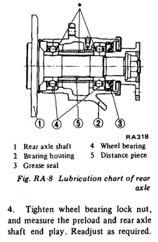
Nissan has several adjustment procedures in the FSM that can conflict, then they don't have specific "readjust" instructions. The rear bearings are pretty simple, you're just clamping a spacer, the "distance piece", between two bearing inner races. Unless the distance piece is thought of as crushable, there is no adjustment possible. The parts are all supposed to be measured and fitted before installation, then torqued, and that's about all you can do. Are people confirming that their distance pieces are parallel on the ends, and the bearings are seating properly? A little tilt would put a lot of leverage on the shaft end. There are five surfaces that need to be parallel. Just some things to consider. Edit - one more thought. If it was mine I'd assemble the stack of two bearings, the distance piece, and the nut together outside of the hub as a quick check of specs. If it's close to right there won't be any gaps. If it's not you'll probably see something. Could be the threaded ends are cut off-axis, which would put the nut off.
-
Both of you should just post your contact information to see if it's the same. It is a business, not a private residence. And how long have you been waiting for a response. One month is not the same as one day. And post the actual torque value used, not "correct", and any details like if never-seize was used. Plus any other details, like maybe peening the lock nut crimp in with a sledge hammer. No reason not to speculate. That's what the forums are about. Joe doesn't need protection. The design elements shown are not very good, as far as stress risers are concerned. Kind of surprising. Does that hardness test take in to account the curvature of the shaft?


