lowrider
-
Posts
404 -
Joined
-
Last visited
-
Days Won
3
Content Type
Profiles
Forums
Blogs
Events
Gallery
Downloads
Store
Everything posted by lowrider
-
A injector duty cycle of over 85-90% is indicative of running out of injector. 100% duty cycle is the injector wide open. Because you changed your fuel pressure and required fuel without any kind of math to calculate the fuel injector flow change with the extra fuel pressure, it’s hard to really know if the injector duty cycle megasquirt reported was true or not. Based on an Internet fuel injector calculator you would have needed to be running 60lbs of base fuel pressure for the 260cc/min factory 280zx turbo injectors to flow 330cc/min. It’s likely that you were locking the injectors up with that high of a duty cycle which would explain the abrupt lean event at/ above 4500-5000 rpm. I’m sorry to hear about the rod knock. It seems like this was a lesson learned the hard way. Be sure to check your pistons because detonation with the intensity and duration to stuff a rod bearing has more than likely taken some ring lands with it as well (from experience). Broken rings/ ring lands could account for the oil consumption. I would also change out your fuel pump to one that will more than accommodate the power levels and fuel type you intend on running for the next motor.
-
Levi.McKinney's 1978 280z
lowrider replied to Levi.McKinney's topic in S30 Series - 240z, 260z, 280z
About time you made a build thread! Now, get some pictures posted up! -
1 x Antique Sapphire Hoodie — L 1 x Graphite Hoodie — 2XL 1 x Heather Heavy Metal — 2XL shipping to: 37840
-
A tale of two Z's - NA vs Turbo
lowrider replied to MONZTER's topic in S30 Series - 240z, 260z, 280z
I just stumbled on this thread! Happy to have you back on the forums! The turbo car and the plenum really inspired me and thus why the Milkfab Manifold came to fruition. Its great to see you back in the swing of things! I cant wait to see your progress on both cars. Also, that exhaust manifold is a piece of art! -
A musician's therapist (The $300 Z)
lowrider replied to Zetsaz's topic in S30 Series - 240z, 260z, 280z
You might have a look at ASA if those PETG pieces cant stand the heat. ASA has similar properties as ABS but is UV stabilized. I have a few interior pieces done in PETG that have held up really well, but I'm not sure if I would trust them in the engine bay/under the car with the radiant road heat. -
I've been following along for a while now, and I love the build thus far! Might I make a few suggestions? First, I would recommend to re-measure the crank journals with a micrometer instead of calipers. The cheaper plastic calipers aren't exactly known for their precision. Another thing to take into account is the taper of the journal, which the micrometer would be able to better measure. Out of curiosity I tossed your measurements in a spreadsheet and calculated a 0.078mm out of factory spec condition with the main journals and a 0.177mm out of factory spec condition with the rod journals based on the info you provided. Personally, I would have the crank checked and the journals turned 0.010" along with having them check the straightness of the crank(especially if it has indeed been riding around in the back of a truck in Thailand). I would hate to have spent so much time and money building this engine for it to have issues. IMO, it would be cheap insurance! I'll have to dig out my "how to modify" book to see what the max acceptable "race" clearances would be but I'm not sure I would risk it if I were in your shoes. I'm looking forward to the updates and progress!
-
The later S30's used 3/4" slave cylinders. I always had issues with my clutch setup engaging at the very bottom of the pedal stroke, and like you, didn't want the TO bearing touching the PP all the time. I made the switch to a 11/16" slave from an '89 240sx and it corrected the issue. My clutch now disengages/engages in the middle to upper end of middle of the pedal stroke. I would confirm what size slave cylinder you have, and then size it a little smaller.
-
Those that are disbelieving that the exhaust liners break and come out, I have experienced it personally. I originally started my turbo journey with a stock F54 flat top bottom end and a P79 head coupled with a Z31 T3 Turbo. It ran well for quite a while but ultimately I broke the rings/ringlands due to inexperience tuning. However before I broke the pistons, I had one exhaust liner break apart and lodge itself in the exhaust wheel of the turbo. Thankfully it was at low speeds and didn't wreck the turbo, it just wedged itself into the fins of the turbine and kept it from spinning. I pulled the single liner and re-assembled everything (I was broke and in college lol); the motor lasted for a year or so after that before the pistons/rings gave up the ghost. I swapped to a stock N42/P90 combo not long afterwards and have had that combo (multiple bottom ends) in various iterations of the setup over the past 10 or so years. I can say that I miss the off boost response of the higher compression flat top combo though.
-
GSP 280zxt CV Axles with Milkfab Engineering Adapters
lowrider replied to FJOVA's topic in Drivetrain
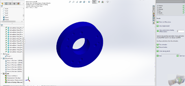
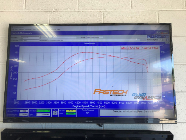
That's correct, I am the owner of milkfab engineering. I can understand your skepticism and welcome it! By no means am I making claims of this axle setup living behind 800hp or even the 800lb-ft of torque that the FEA (finite element analysis) for this adapter design was performed at. Most aren't interested in or don't understand the technical details, but I am more than happy to provide them. Below is a screenshot of the FEA that was performed in Solidworks when designing the parts. A 5000N load was applied tangent to the center axis to each of the 6 axle mounting holes, which are radially 40mm away from the center axis. The mounting holes that attach the adapter to the stub flange were held as a fixture point. Granted in a properly clamped configuration, the mounting holes are not going to be seeing the entire load like modeled. 5000 N x 6 (mounting holes) = 30,000 N 30,000 N x 40 mm = 1,200,000 N-mm 1 N-mm = 0.00074 lb-ft 1,200,000 N-mm x (0.00074 lb-ft / 1 N-mm) = 888 lb-ft As you can see from the screenshot below the FOS (factor of safety) is 2.59. As for the axle testing I have done no formal lab testing. I just have my word and the testimonials of several customers. I have had the setup on my personal car for the better part of 7 years like I said above. Within that time it's been subjected to numerous hard launches, burn outs, and a few runs down the local drag strip on street tires. I have not found the breaking point of the axles yet, but we all know that usage is the determining factor. If I were taking to car to the drag strip every weekend on radials they are more likely to break than if I am launching on a street tire on an unprepared surface. As for the power claims of the old worn out L28et in my 260z I recently had the car dynoed this past spring on a local dyno dynamics dyno. Going into the session the shop made it clear that the dyno was a "heart breaker" and read similarly to a mustang dyno. I am not a huge fan of using the dyno to produce quantitative results when compared to other dynos, but according to varying sources the dyno dynamics dynos read on average 10-14% lower (take that with a grain of salt) than the more common dynojet that most use as a baseline. The car made 317.3 hp / 351.8 lb-ft in 86.5F weather. Approximate a 12% lower rating than a dynojet and you're left with roughly 394 lb-ft of torque if the car had been ran on a dyno jet. That is why the website mentions ~400 lb-ft. There are also other customers that are in/around that same power area and running without issues, a simple Facebook (I hate refering people there) search in any of the large Datsun groups with pull up the posts. Here is the dyno sheet for your reference as well. I apologize for being so long winded. I try my best to be as transparent as possible when it comes to the development of the products I provide. FWIW, these adapters/axle setup were designed for my personal use with no intention of being sold. It wasn't until there was interest some 5 years or so later that I considered making them to sell.
-
GSP 280zxt CV Axles with Milkfab Engineering Adapters
lowrider replied to FJOVA's topic in Drivetrain
The torque limit of the milkfab setup really depend on usage. The adapters themselves were designed to hold more than the ~400lb-ft torque threshold stated on the website. Not taking into account shock loading from hard launches, a static FEA of the adapters showed there was a safety factor of 2.5 at 800lb-ft of torque. Will the axles hold at that? It's yet to be seen and really wasn't the intended market. For context, the milkfab adapters with 280zxt axles have been living behind my ~380lb-ft L28et for the better part of 7 years with no problems besides a torn boot. I had issues with breaking u-joints in the half shafts prior to the upgrade due to drive-line angles and torque. Even the power-force (or was it brute-force) grease nipple less u-joints weren't holding up. The main reason why the stated torque is~400lb-ft on the site is that it has been thoroughly tested at those power levels. -
You are correct in your assumption that one leg is the signal ground and the other two pins are the high and low signals. There should be continuity across the common pin to the low pin at its switching temp as well as the high at its switching temperature. If you aren't getting continuity across any of the pins it might be fair to say the sensor is bad.
-
Compatibility 280ZX Turbo Cv axle/Companion flange upgrade to 280Z
lowrider replied to Jyarb's topic in Drivetrain
Check out: https://milkfab-engineering.com/shop/ols/products/240z260z280z-cvaxlekit -
Unique Factory Oil Cooler O-ring, what is the part number?
lowrider replied to himself's topic in Nissan L6 Forum
If you have the dimensions from the original it would be fairly easy to look up a comparable o-ring from some where like McMaster Carr. -
Thoughts about installing carbs on an na2j?
lowrider replied to chatapokai's topic in Toyota L6 Forum
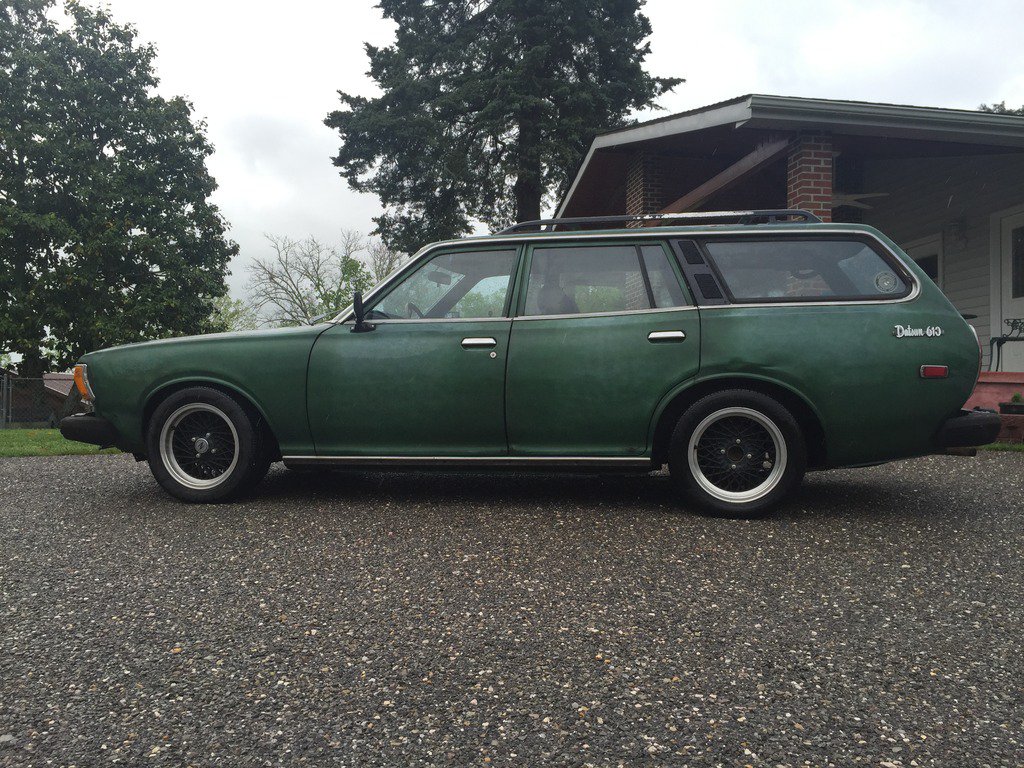
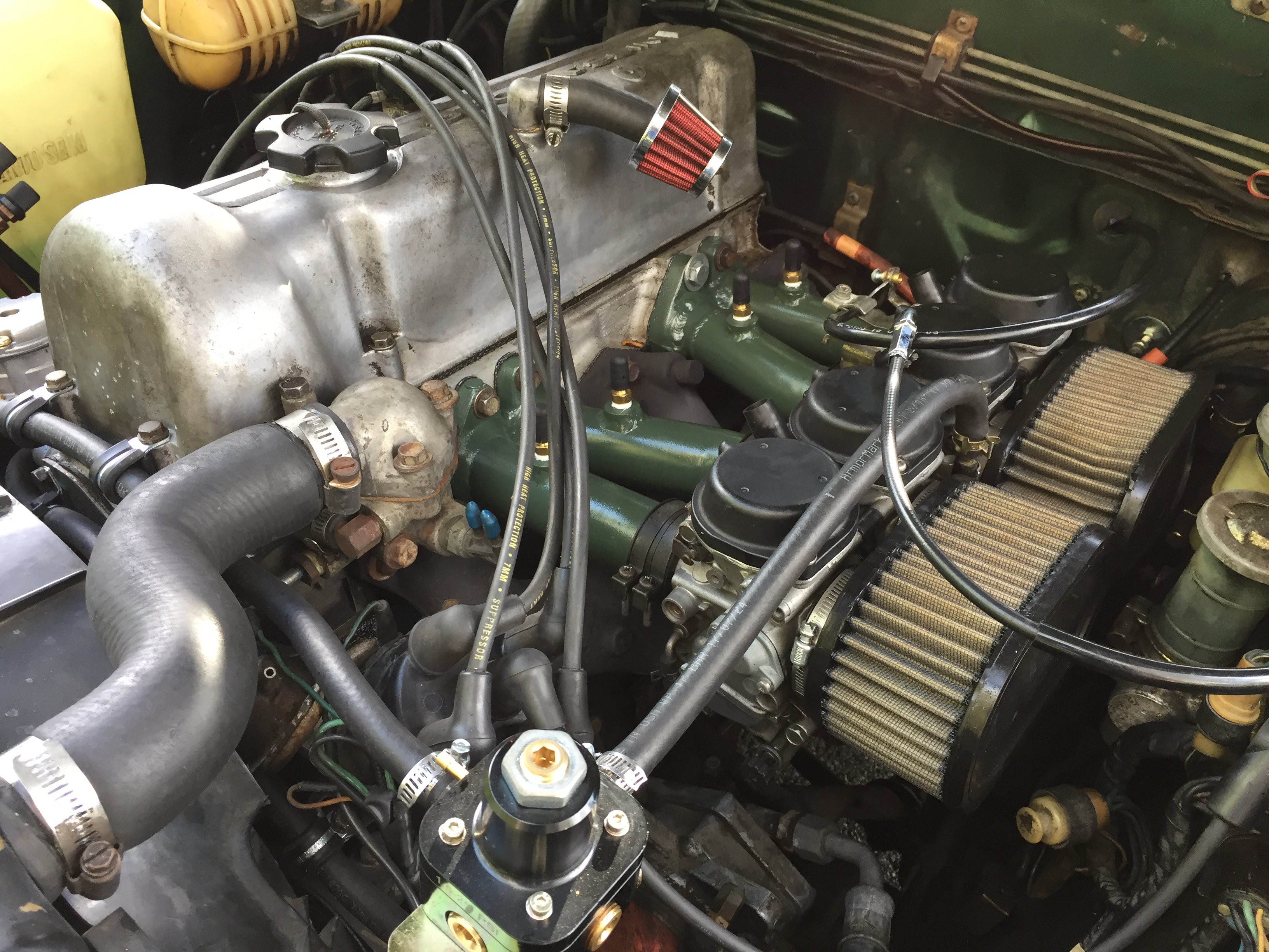
Why not run an electric vacuum pump instead of tying all of the runners together? I did a Mikuni bike carb swap on my 610 station wagon and ran this vacuum pump for the master cylinder and other vacuum driven accessories. I pulled mine from a Volvo in the local pull-a-part and paid next to nothing for it. I have it connected to switched power via a rely and inline fuse with an inline vacuum switch to activate the relay. Whenever the vacuum level drops below the switch threshold it will run for a few seconds then shut off. It's been working great for several years now! -
Wrong rotors, buyer beware.
lowrider replied to Cruzzar's topic in Brakes, Wheels, Suspension and Chassis
The mounting bold diameter for the rotors is correct at 103mm. The rotors don't slip over the wheel mounting studs like in newer model cars they bolt to the rear of the hub. The mounting bolt pattern to attach the rotor to the back of the hub is 4x10³. Source - I produce brake kits for the S30 and have personally measured the rotor mounting bolt diameter. -
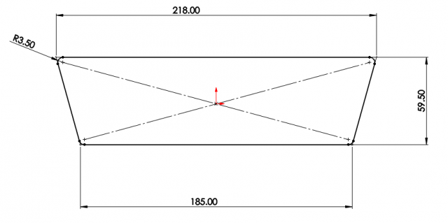
I made a radio block off a while back that houses 3 52mm gauges. Here are the dimensions. I'm not sure what filament you plan on using, but I don't suggest PLA.
-
It's great to see some more people from East TN getting into the Z family. We have quite a few experienced Datsun guys in and around the Knoxville area. Chassis wise there are a few considerations. The 280Z chassis is touted as being stiffer than the earlier chassis'. An earlier chassis can be stiffened, but it involves more work/funds. Personally I would choose the starting point/chassis that would be in the best shape your budget could afford. The least rusted car you can find/afford the better off you are in the long run (IMO). I have my 260Z is setup for cruising/mountain driving/to be well rounded. I doubt it would be competitive in any of the local autocross events but it would certainly be fun. If you'd like i would be happy to get some of the guys together and have a sit down with you. If anything, you would have a few Datsun contacts in the area then.
-
I still have my stock head unit, but it is simply a place holder. I have a Bluetooth module feeding directly into a 1200W 4 channel amp and a "spare tire" sub in my spare tire well. Up front I have 5x7's under the fronts of each seat and 2-1/4" tweeters/mids in the dash vent pockets. In the rear I have two 6" speakers in the factory locations in the plastic side panels. The sound distribution is pretty good and the spare tire sub provides just enough bass.
-
Take a look at the RPM gauge in Tuner Studio when you attempt to start up. If you have a tach signal the RPM gauge should show ~400 RPM while cranking. Are the PIP and SAW signals hooked up correctly to MS? If they are swapped, the MS wont see an rpm signal.
-
I don't have a lot of experience running E85, however from what I've researched it has the tendency to absorb moisture from air after a period of time if the gas tank is left vented to atmosphere. This can cause some issues with corrosion in various areas of the fuel system in this case it could cause rust to form in the tank. I wouldn't be terribly concerned with it as long as the E85 isn't left in the tank unused for extended periods of time. I would also look at replacing the vent and fuel filler hose to an Ethanol compatible material. As for the Walbro 255, depending on the power goals of the car you might find that it wont provide enough flow due to needing 30% more fuel with Ethanol in comparison to Gasoline. It may be something to take a look at.
-
I apologize for a super delayed response. It's not expensive at all to plastic cast pieces like this. The molds are made from silicon and are taken from the 3d printed part. A few well placed fill and vent holes in the mold and you are good to go. If you're interested in the process there are tons of YouTube video tutorials that show how to do it from beginning to end.
-
I appreciate the words of encouragement. I have since ditched the P79 in-favor of a solid converted P90a. I'm still planning on picking up a spare P90 to port one of these days, it's a perfect excuse to build a DIY flow bench.
-
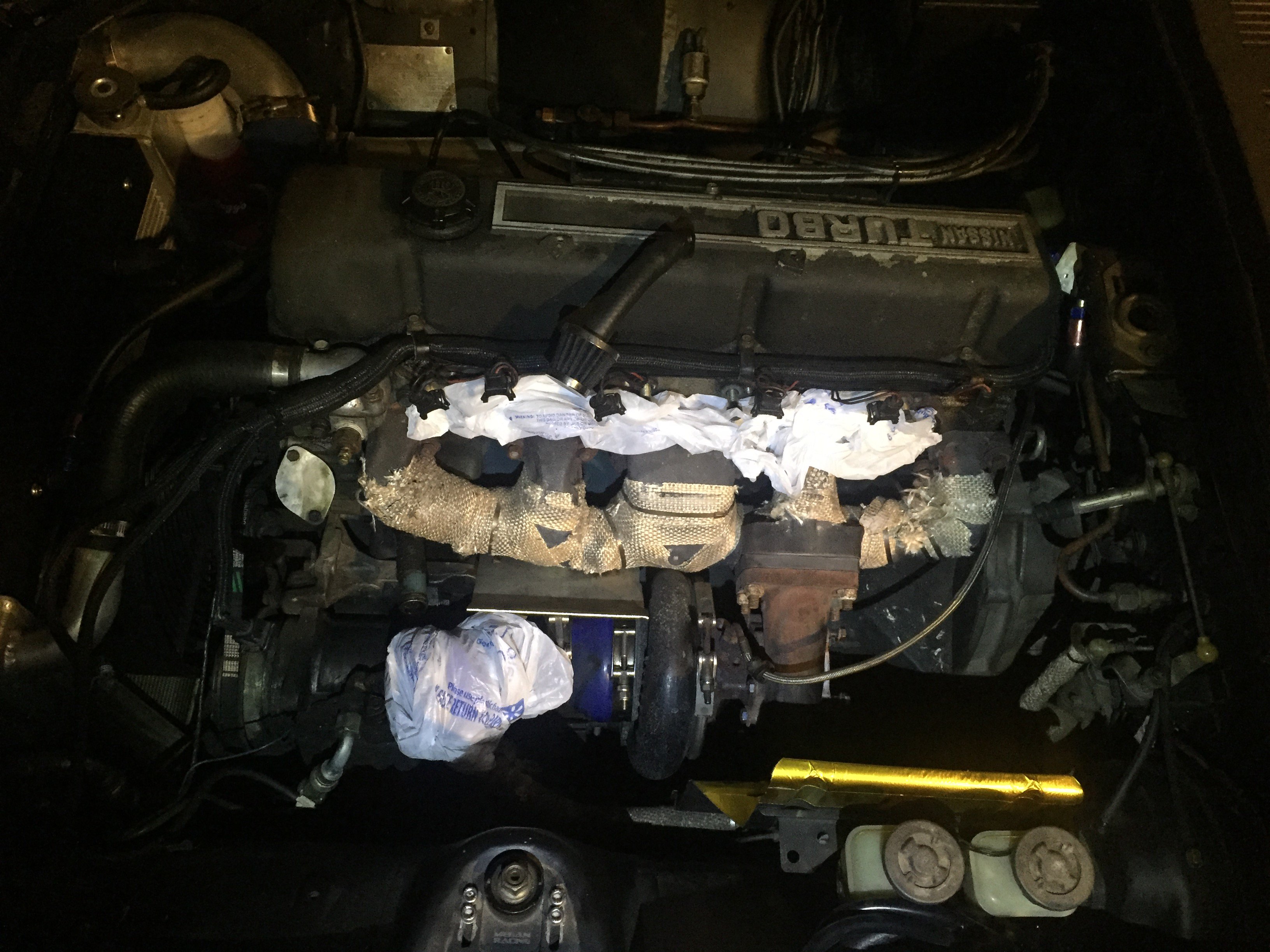
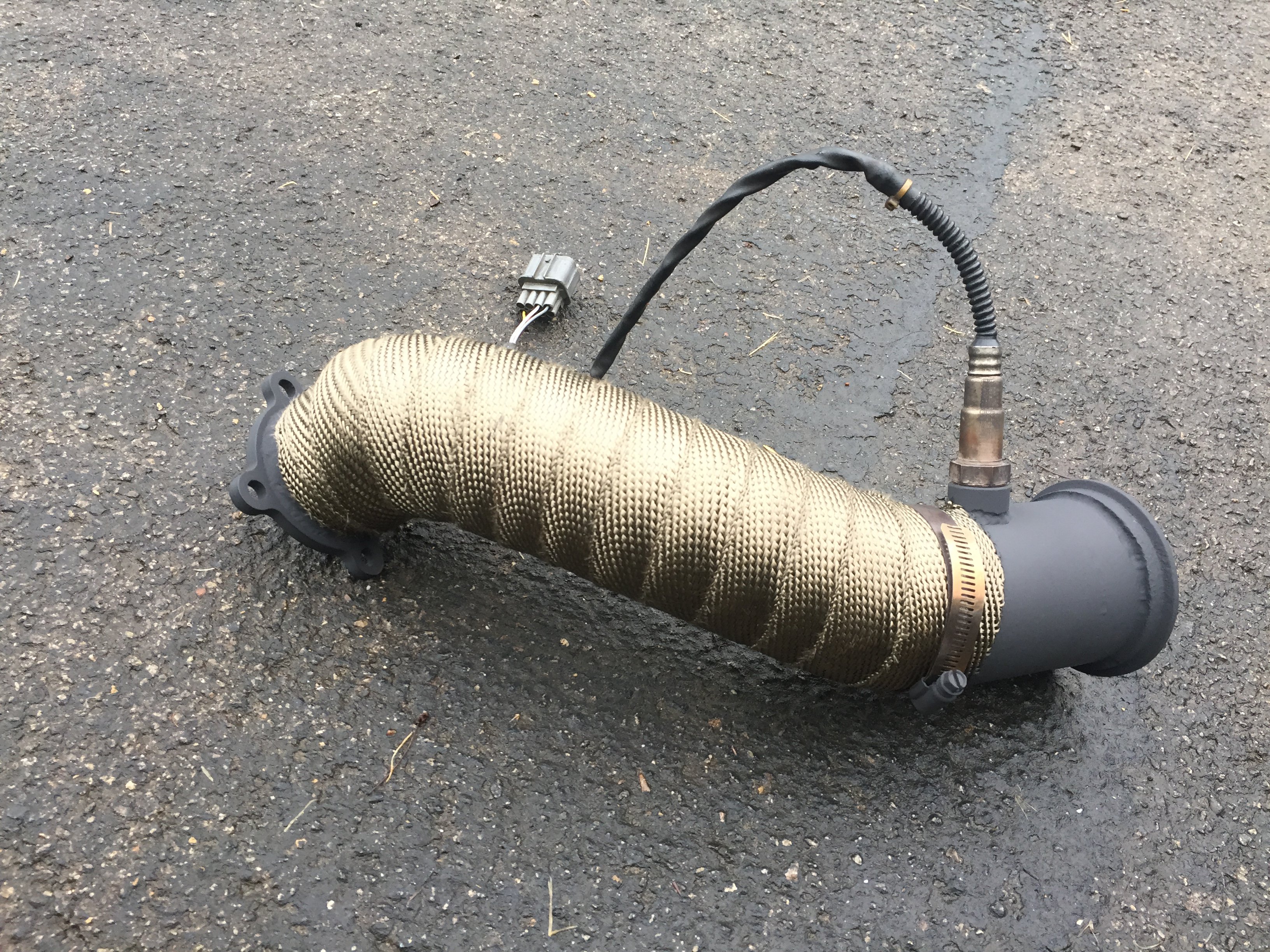
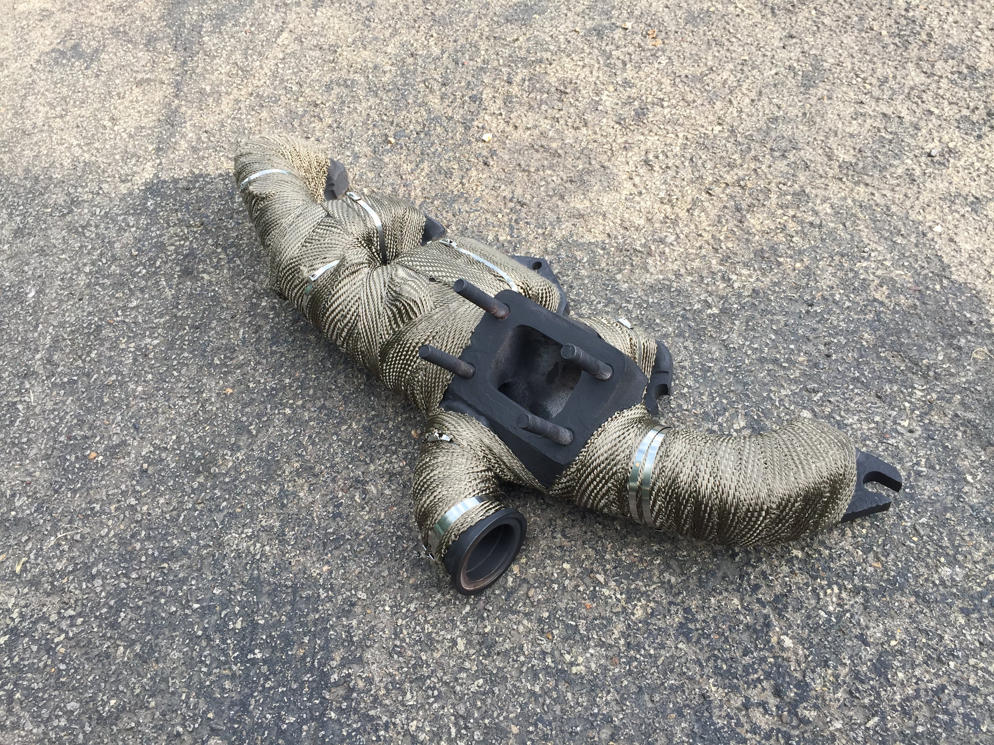
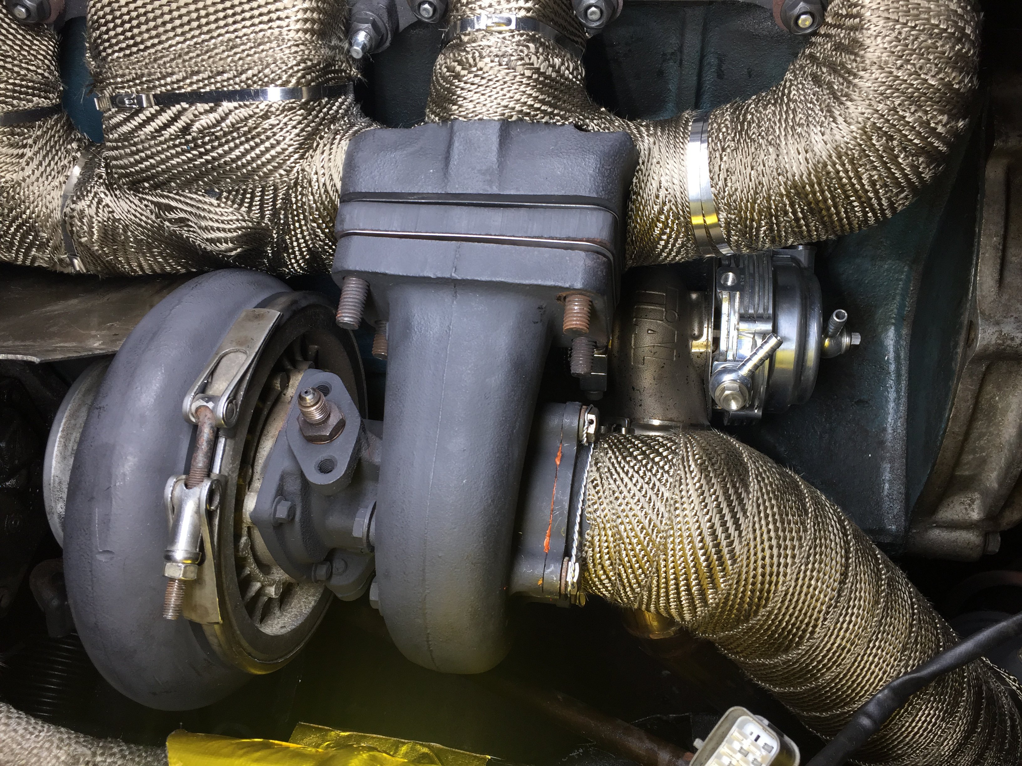
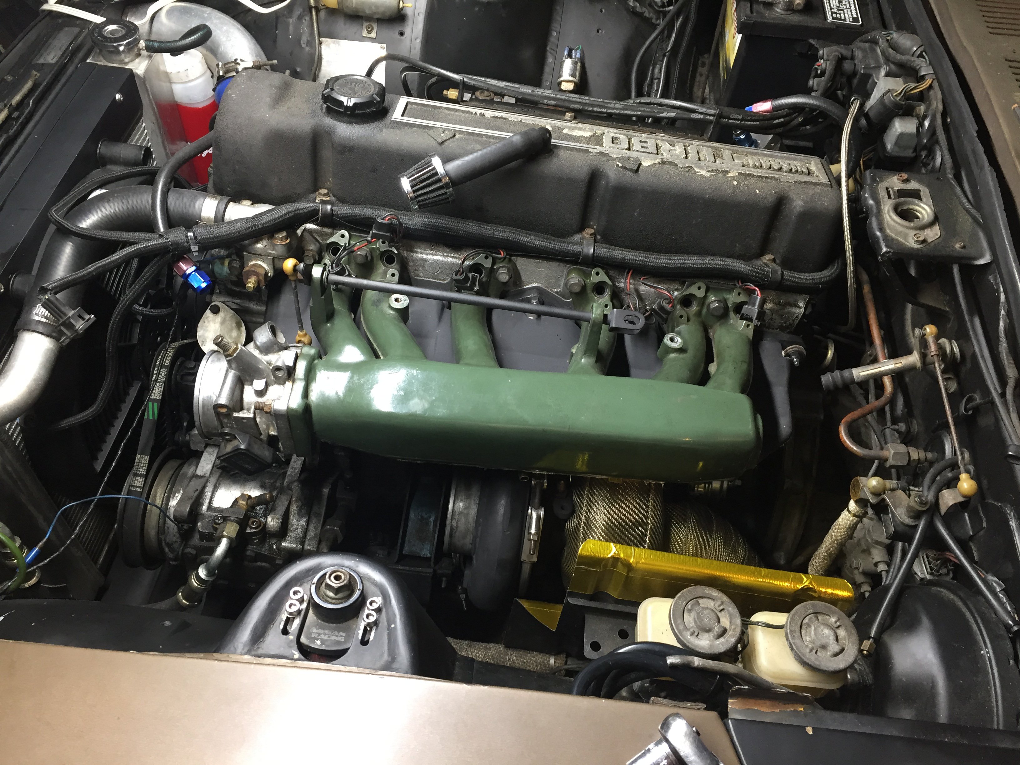
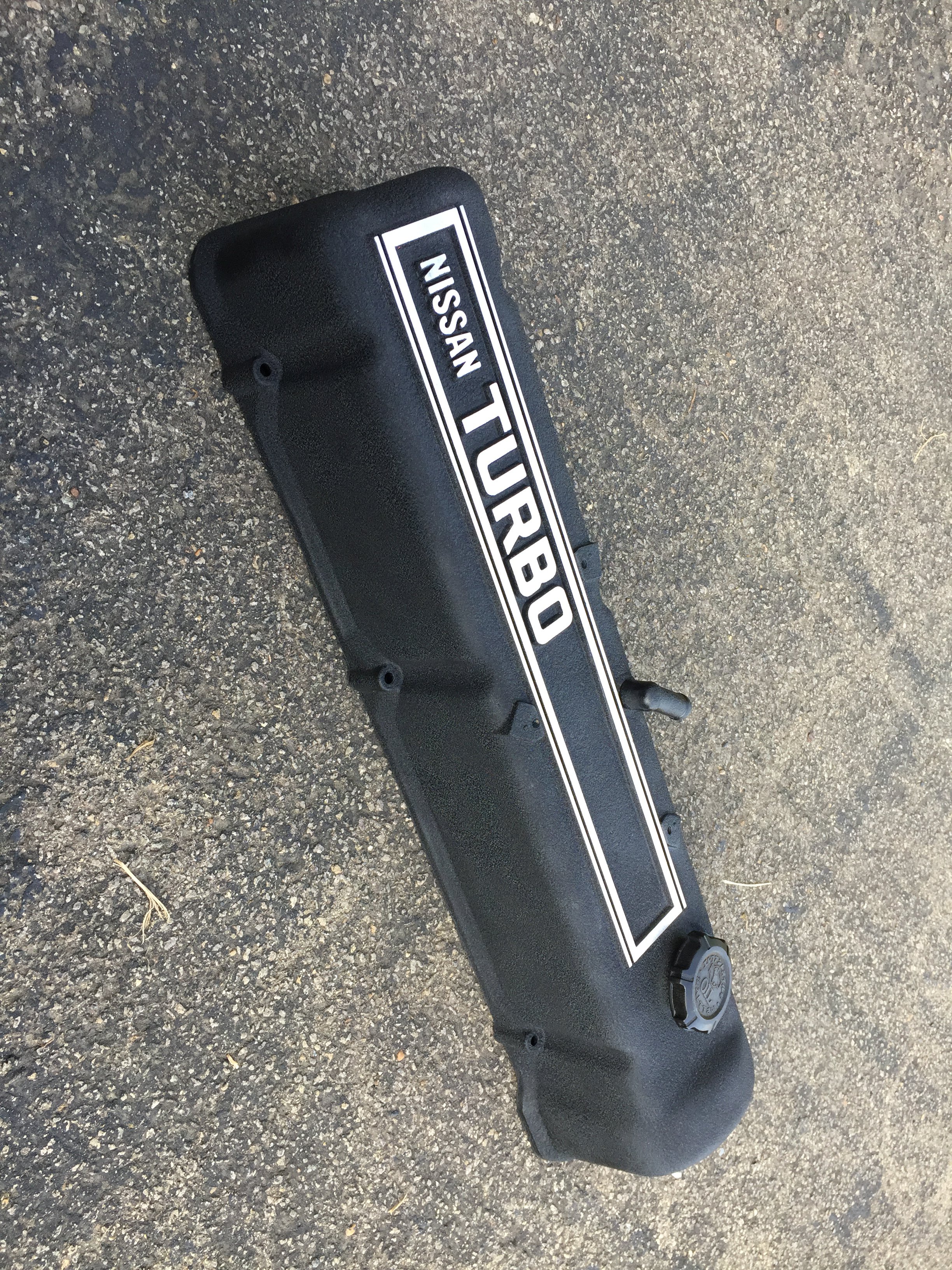
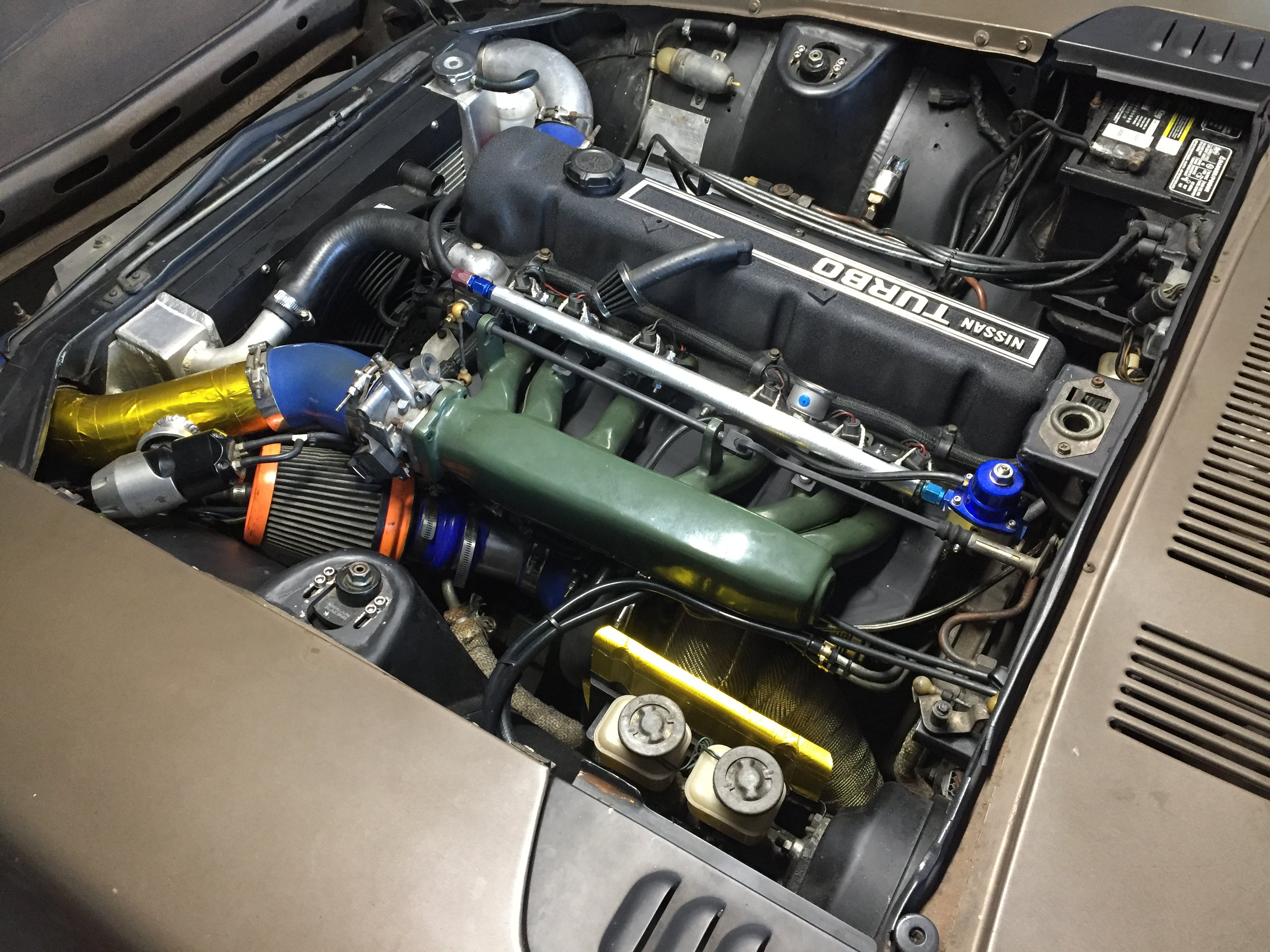
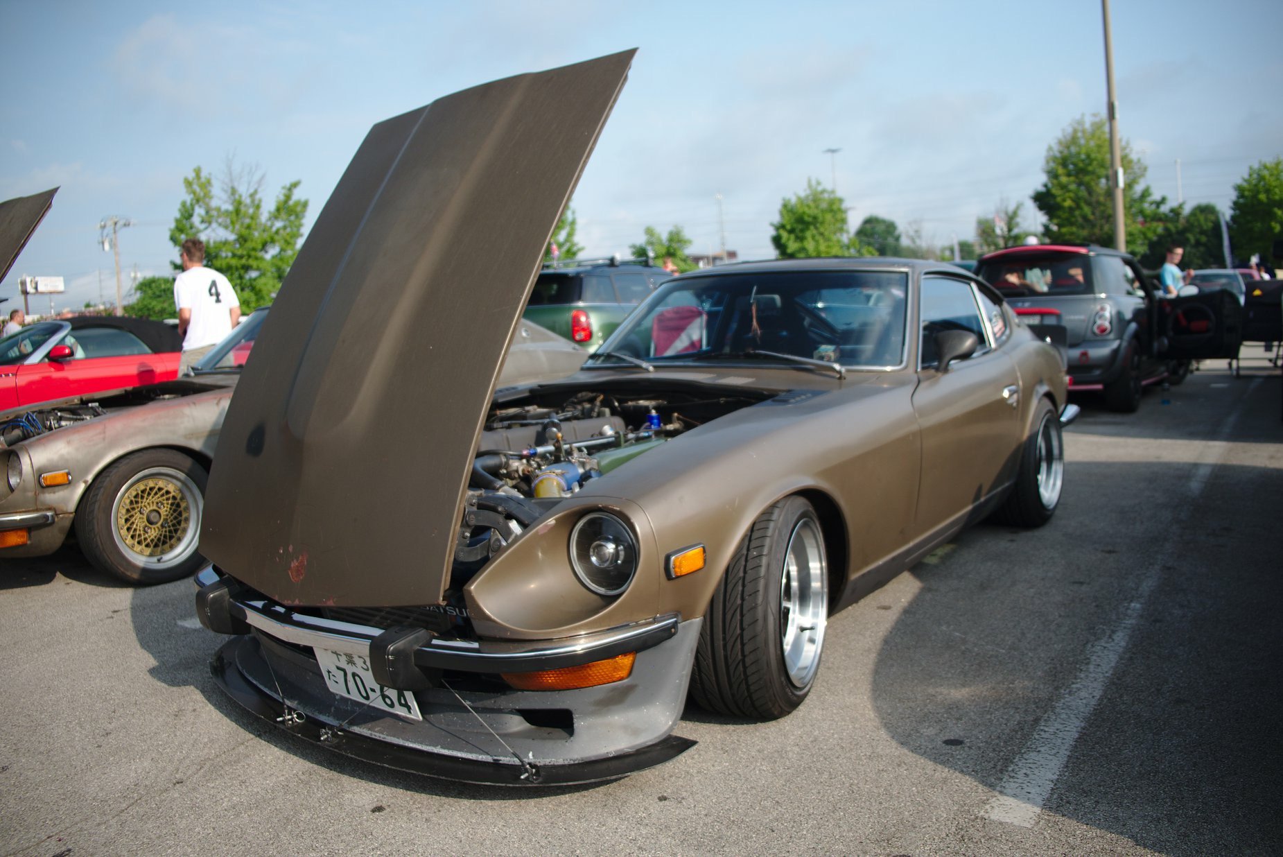
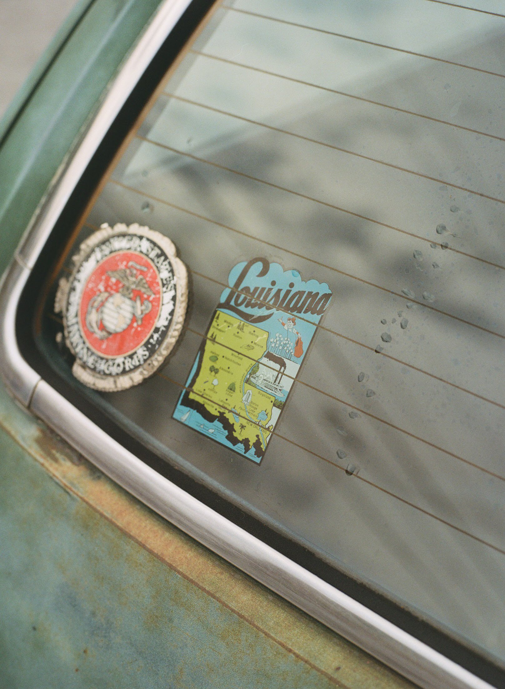
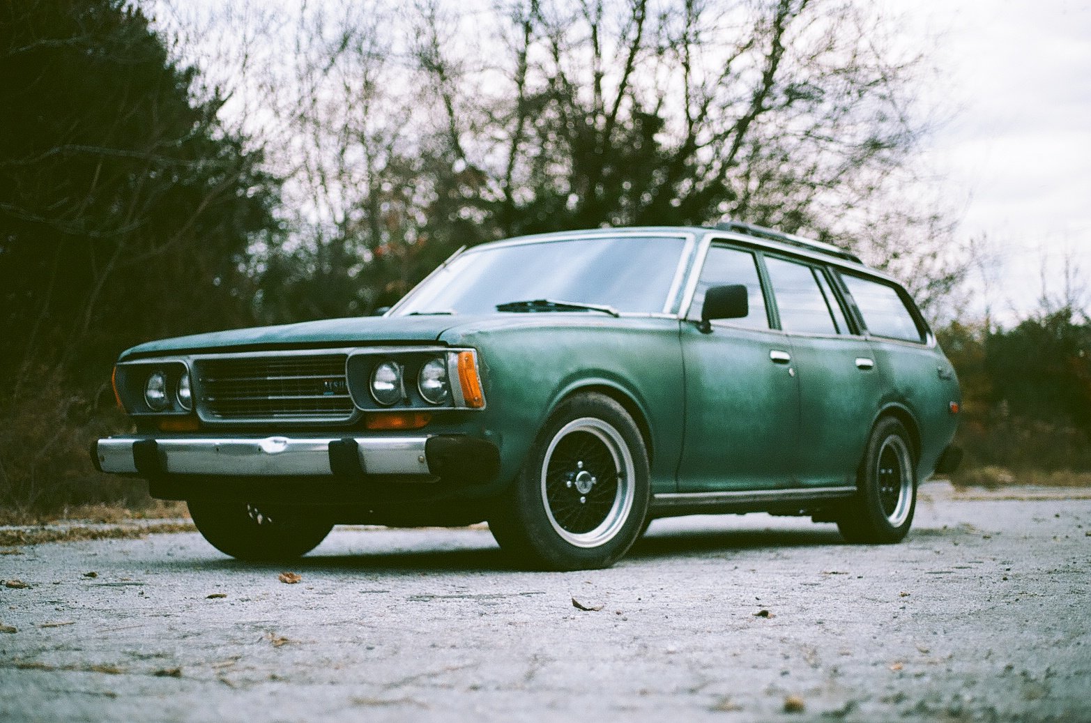
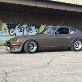
Update: I just realized that this will be my 4th update this year, talk about a major improvement from years past. I believe I left off with attending Zdayz this past May. In previous updates I had set a list of things that I wanted to get done on the Z. The list was: I completed the marked out items before going to Zdayz, which left numbers 4 and 5 on my list. I decided to start tearing the engine bay apart after I got back from Zdayz with the deadline of taking the car to the Cars and Coffee event that is put on three times a year here in Knoxville. I started by tearing the intake and exhaust manifolds off along with the connected components. You can see how tattered and worn the old heat wrap was on the exhaust manifold and how rusty the exhaust housing has gotten. The valve cover paint had also been wrecked by the freaking rats defecating and urinating on it. So, I pulled the intake manifold first and the turbo, down pipe, and exhaust manifold followed. I started with the down pipe and turbo first. Everything got a thorough inspection for anything out of the ordinary like wear or cracking. This was followed up by a deep cleaning and fresh 1200 degree high temp flat black grill paint. Once everything was painted, it got a liberal wrapping in DEI Titanium "header" wrap. The turbo exhaust housing also was treated to a matching "lava" turbo blanket. This picture also shows how I added the external wastegate to the factory exhaust manifold. The intake manifold got a thorough cleaning as well. The heat shield was repainted in the same flat black grill paint and the underside of the heat shield and intake manifold received a fiberglass mat/ silver reflective heat barrier to try and repel the heat from the exhaust manifold. I also added DEI heat tape to the fuel injector bodies as well as adding reflective heat blankets that wrapped around the injectors. I actually did alot of research into the fuel vapor lock situation that plagues these cars and found that the 4.0L Jeep L6 has the same problems. I found numerous posts on the Jeep forums referring people to wrap their injectors in heat tape and urging people to purchase the "injector blankets" to solve the heat soak issue. I figured for the price I would be more than willing to give it a try and see if it solves my hot start problems. I also got tired of destroying wastegate diaphragm on my eBay wastegate and went ahead and installed the Tial piece I've had on the shelf for the past few years. Last but not least I repainted my valve cover in wrinkle black and put everything back together. At this point, I enjoyed driving the car on occasion during the summer. It kinda took the back burner to driving, working on, fabricating, and installing bike carbs on my daily: I made the deadline to get the Z to Cars and Coffee. I was even able to park next to my good friend that also has an early 260Z he is in the process of building. As far the heat management is concerned on the Z, its crazy what some exhaust wrap, turbo blanket, and reflective heat wrap can do. I immediately noticed an improvement in the turbo spool response. I now had issues with the compressor hitting the surge line while using the throttle to try and regulate boost pressure. I did some re-configuring on my BOV so that under high pressure differentials between the intake manifold and before the throttle blade it will vent slightly, allowing the compressor flow to move right of the surge line. The car was driven on occasion with no real issues, even in the heat of summer it never had a problem. It is now in "winter storage" with tons of rat and mice repellent in and around the car. Bonus content: Recently I was given a hand-me-down Canon AE-1 Program from my wife when she upgraded to a digital Nikon. I am a complete Noob when it comes to doing any kind of photography let alone using 35mm film (which you cant tell how the photos turned out until developed). I have a good friend of mine that is super into analog photography so we got together and did a slight photo shoot of the Z and the Wagon. Hopefully this isn't a picture overload on the server. Those of you that see this and make it to the end: I hope you have a Merry Christmas and have a Happy New Year!!
-
@theczechone, I would be curious if this was using the stock inductive type dizzy or a points type. If I remember correctly (I don't want to spread misinformation) the 260Z dizzy had two inductive pickups, if that were the case I could see where that might cause problems. I would be interested in what you find digging deeper.
-
My pops pulled the trigger on one of these for his 66 Fairlane with a 390. I will likely end up setting it up and ultimately tune it for him. Pending my experience and his results I will likely purchase one for my soon to be force fed, Mikuni bike carb powered L20B that is in my daily driver. The bike carb conversion has eliminated the ported vacuum so I’m currently running without vacuum advance. The CB Black Box has proven to be the most economical solution to digital timing control that I could find. As far as the timing variation is concerned, I will measure it on my dads car when it’s installed. I haven’t measured but I believe the V8 is going to be the most limited by the amount of timing advance I can dial in before arcing across to another post. I will say though, CBPerformance is currently powering high horsepower(300hp+) NA air cooled engines with this setup so it should do all that we need for a relatively mild 390 and little ole’ L20B.