Leaderboard


Popular Content
Showing content with the highest reputation since 03/04/26 in all areas
-
Since that broken rear differential a lot has happened.
 4 points
 -
3 points
-
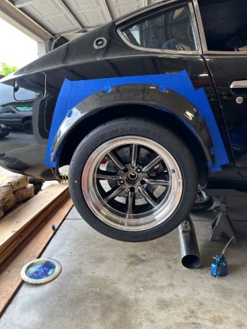
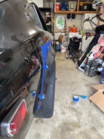
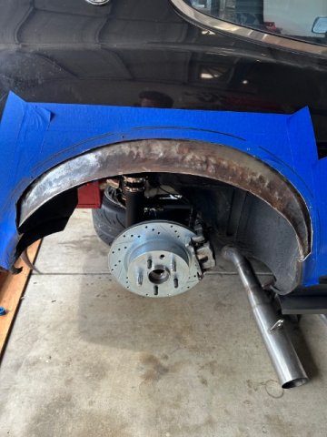
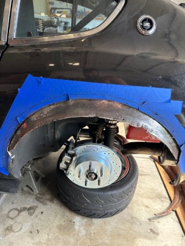
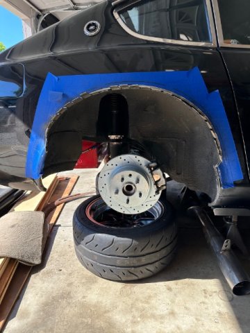
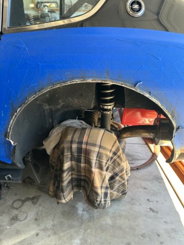
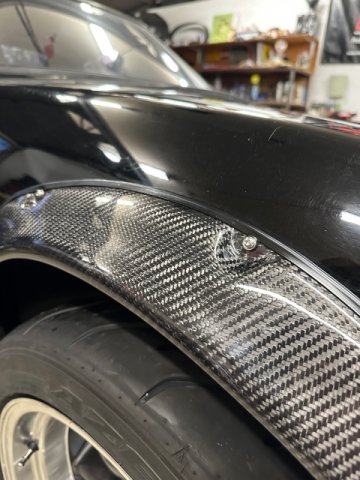
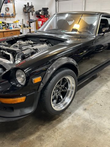
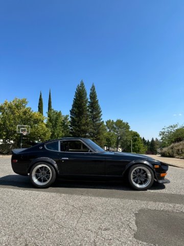
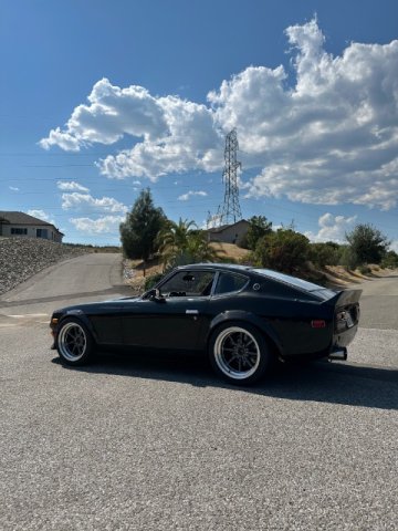
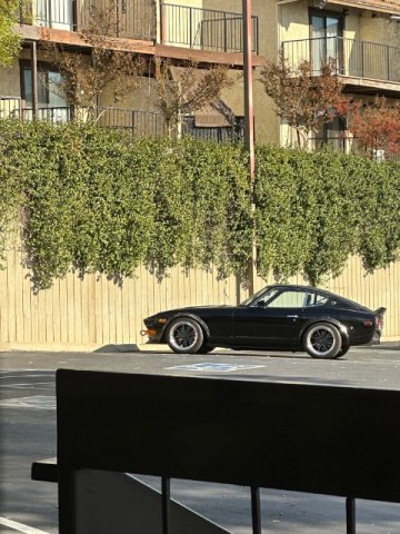
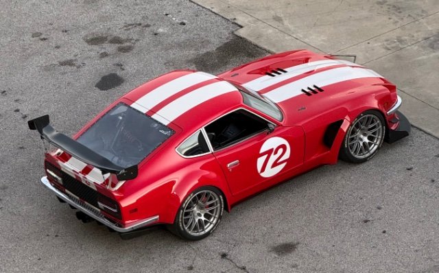
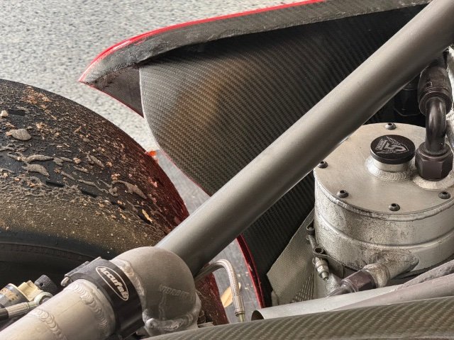
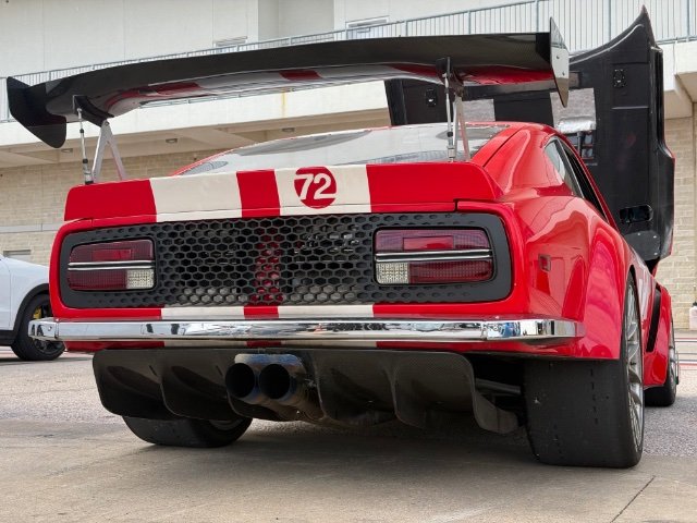
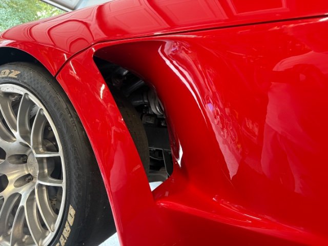
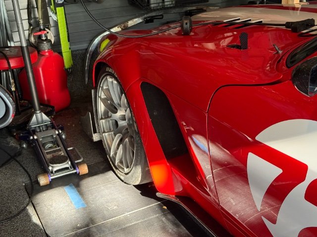
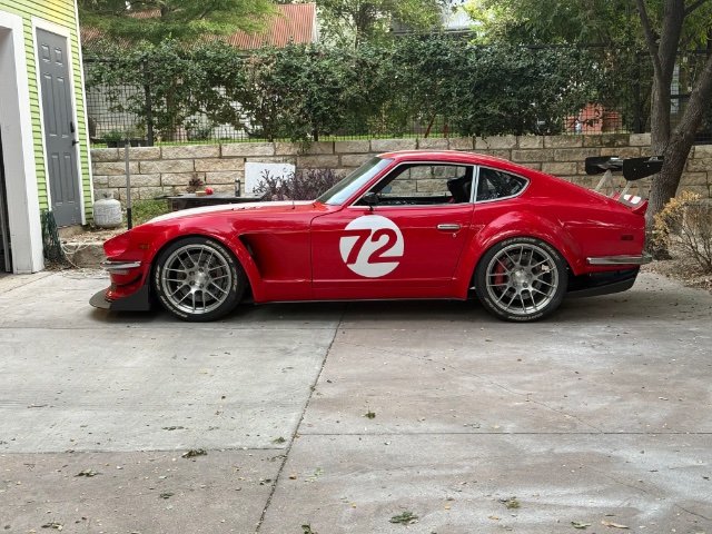
if anyone's still tracking this build I have what might be a last update since the car is mostly done (lol is it ever done?). I finally cad-designed the front fenders and then had a local shop 3D print the parts, then took that to a bodyshop to integrate into the existing fender part and paint it. After that I overlayed the inside walls of it with carbon fiber for added stiffness and protection. I also cut the lower part of the rear fenders and put in a horizontal cf winglet to better extract air. Overall I think it looks great and the resulting new parts helps downforce a ton by extracting air from the wheel wells.
3 points
-
Unrelated update but reasons as to why there's been a lack of updates to this thread: Got a new job that demands a lot more of my time so unfortunately less time to optimize the SLA conversion. Upside however is that I'm learning NX which seems to be some next level software. I think this design is going to take one more fundamental change to really get the dynamic geometries perfect but the work I have so far has been a pretty excellent starting point. The car is also back from the rust repair shop and the cage shop, needless to say my wallet is in a lot of pain at the moment (especially with the S54 being built) but we do these things not because they are easy but because they are hard and we hate money. Anyway, enjoy some photos of the cage in the meantime.
3 points
-
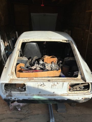
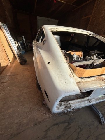
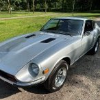
Congrats...that shell looks pretty dang straight! As much as I hate to admit this, you'll probably get quicker/more responses to that particular question via Social Media. I can recommend some pretty good Z-car pages on FB, if you like. I wouldn't usually recommend FB for technical questions/discussions....but for an administrative question on a re-title, it might yield some good results for you. Again, welcome to the forum; and please keep the updates coming as your project progresses. What are your plans/goals for the car?2 points
-
That has got to be the best balance of Form and Function of a Datsun that i have EVER Seen!! Absolutely amazing!!2 points
-
I have been here for long rime, just not lately. I have a nice 83 280ZX Turbo. Which started me on this site. I just modified ,restored a 71 240Z. Both are 5 speeds. I love them both.2 points
-
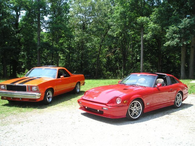
My toy house 71 240, 83 280ZX turbo and my built 78 El CaminoSS.
2 points
-
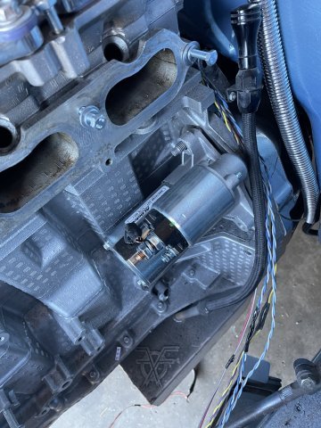
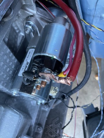
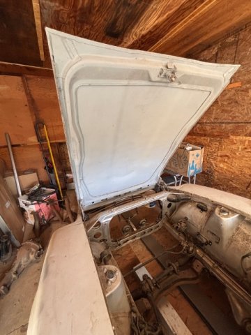
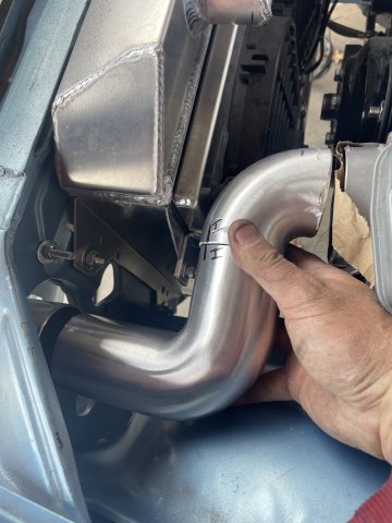
03-07-2026. ATLAS Z UPDATE: I started with the intercooler piping on the turbo side, and have it ready for welding, sanding and polishing. I got started on the intake side, but ran out of parts. Since I had to pull the intake, I enjoyed the easy access to that side of the engine, and installed my new AC Delco starter, and wired the solenoid and main batt power on it. I also was able to plug in the harness points on that side of the engine, install the crank position sensor and both knock sensors, all new GM stuff. Started on the alternator bracket modifying, much more on that to do. Feel got cold, called it a day. PICS
2 points
-
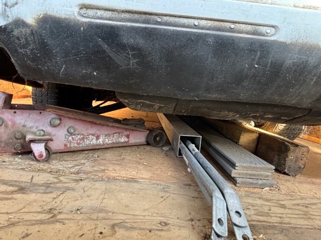
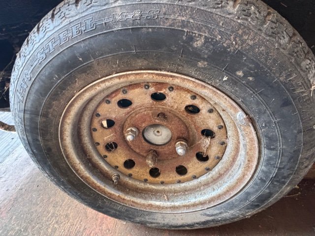
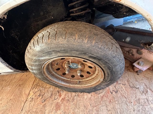
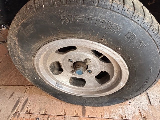
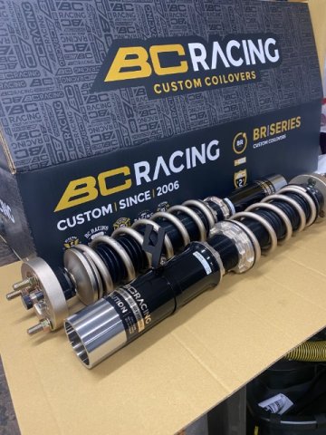
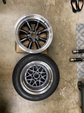
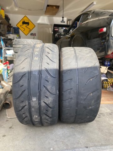
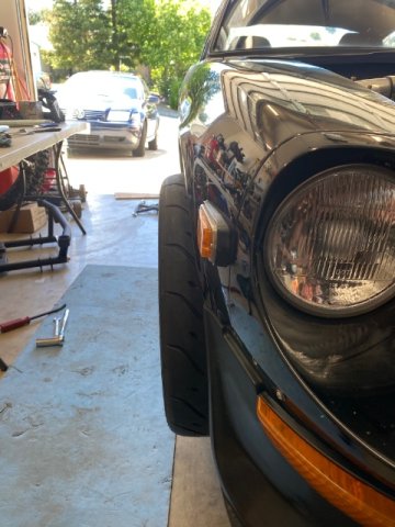
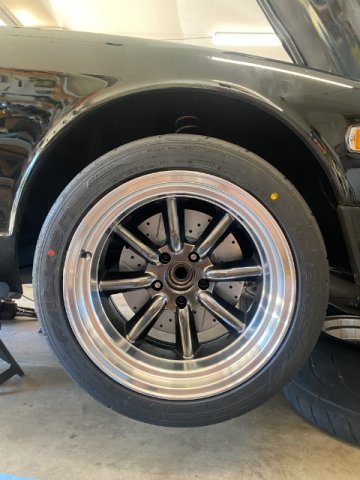
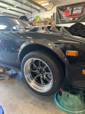
Committed to new tires. Far less weight to balance them as expected. The inside was more worn than I realized on the old ones. Went with Yokohamas in 205/55/15. Skinnier than I wanted but they were half of what the 200tw options were, weren't so aggressive, and they'll give me a couple more years of use before I spend bigger money to go up a size. Currently working on getting the AC condenser and drier mounted with the new hardware from vintage air. I'm hoping the drier JUST clears the intercooler, but I'm anticipating it being tight. Will be making new lower brackets for the intercooler as well. You can see in the pic they're extremely bent because they were so flimsy. As they say... Nothing is more permanent than a temporary solution.
1 point
-
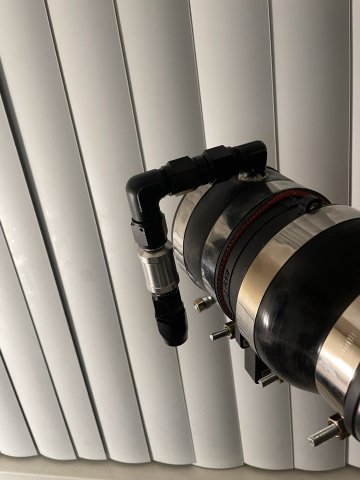
03-25-2026 ATLAS Z UPDATE: I got some of the fittings in I need for my crankcase pressure to catch can to intake setup. Also tall of my carbon fiber panels have been cut, final polishing on roof section then ready to ship to me and bond them on! Then make the borders shiny!
1 point
-
What oil pan are you using? You'll have to set the motor back really far to get a front sump pan behind the front crossmember. I'm using an Aviaid Mangusta pan on mine and I needed a custom crossmember to get the front sump to clear.1 point
-
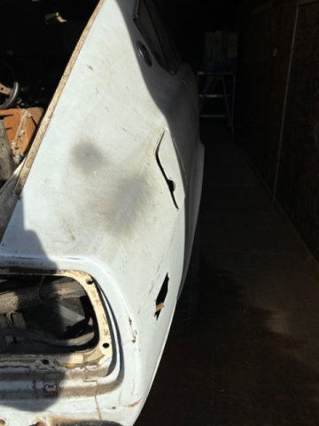
My efforts to get this other Z back running have expanded quite a bit beyond the rebuild of the 3.0 stroker motor. At the moment, I am working on repairing some rust in the floor panels. I have been watching a number of "Make It Kustom" videos on Youtube by Carl Fisher. In one of them, he creates some forms out of 3/8" plate to create a "hammer formed" part. Additionally, he uses a hydraulic press to "stamp" a recess into the battery tray he is making in the video. The rust in my floors on this car is not extensive. It is generally in the area of the large oval depression in the floor panel (on both sides of the car). Yesterday, I spent a few hours cutting out and grinding/filing on part of the form I plan to use to replicate the depression. On the right side floor, I only need a small portion of it. On the left side, I will attempt to make a full piece to replace the depression. I've never done anything with forms likes this, so we'll see how it goes. I will be using my 12 ton press because it is what I have to attempt to make the replacement part. But, I have been watching facebook for a suitable upgrade, perhaps a 30 to 45 ton press.1 point
-
It's been one of the busiest years of my life but the turbo build continues in the background. Since the last update, the circuitry has been mapped out so I visited the chassis to start installing the mil-spec bulkhead and radlok connectors. Generally, the plan is to run Haltech for ignition control, knock detection, etc. and ditch all piggyback systems which I'll probably recycle on another ongoing turbo project. Only the best for the Z 😉. The resto shop is doing a fantastic job with great attention to the details. They've installed the sweet Capital Metal Works full length framerails and started massaging bent OEM sheetmetal back into shape, along with continuing to metalwork other detailed aspects of the chassis.
1 point
-
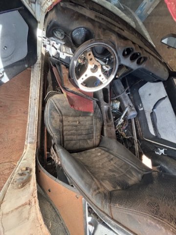
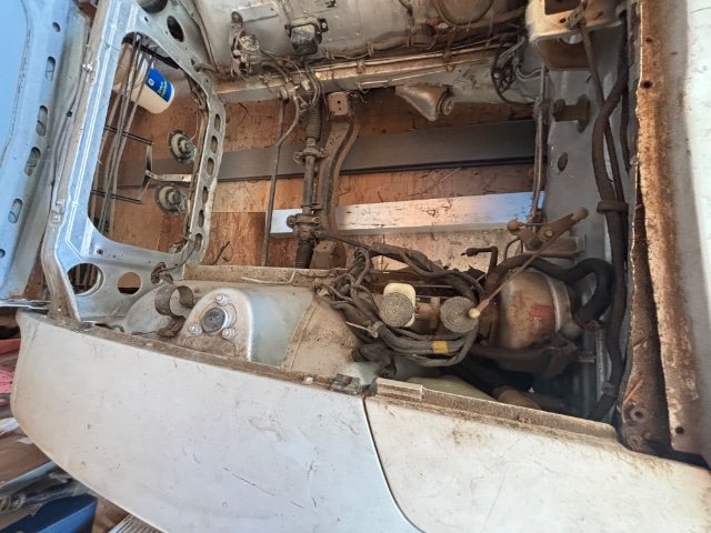
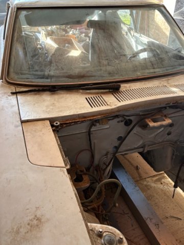
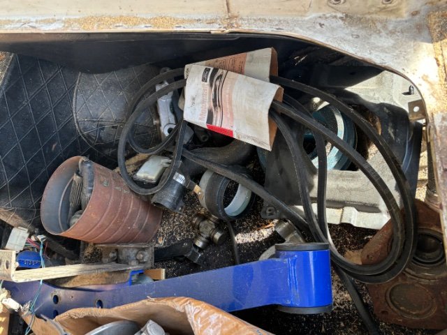
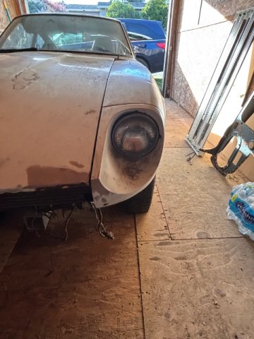
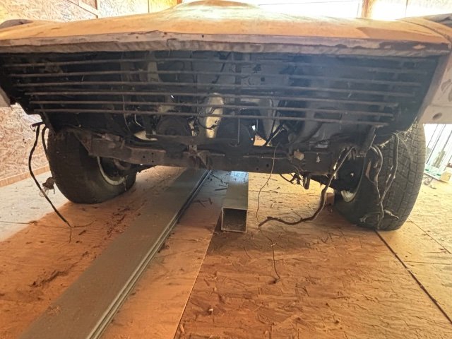
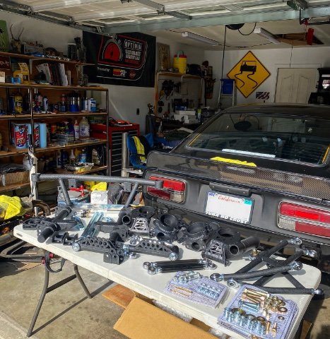
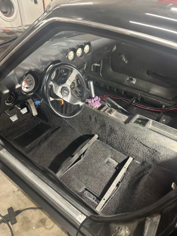
Cage is done. Driveshaft arrived. its comically short. i dont know if i even mentioned it in this thread. I bought the engine with a 350z six speed and tried to fit it and didn't like it so i switched to a tremec TKX 5 speed with a scatter shield. lighter, smaller, better gearing, serviceable. shifter position is great, and not 20+ years old. Mounted a 240z ebrake handle in place to help connect to the 300zx rear cables. Started getting the dash sorted. FIA bars are certainly making it extra challenging to do a clean install. Pedal box is in and throttle pedal is fitted. I don't know what the pedal is even out of but it was sitting in a box that came with the car so I made it work. feels good on the foot. Mounted the heater box to the tunnel. designed and 3d printed some ducts that go to the factory defrost ducts. i also added a small foot diverter for the wifes feet as shes always cold. Mounted the oil cooler. went thru a few ideas between laying it flat and ducting it, stacking it. putting one in the wheel well. etc. Although a 3 stack is not ideal i decided to try it. Can always move it around if its impeding flow to the coolers behind it to much. probably do some sort of screen infront of everything when its on track to keep debris from damaging it. Got my front valance quickly mocked up. I forgot the headlight buckets were a bit beat up so added that to the list of things to fix. drivetrain is basically all set so I am pretty close to pulling everything out and starting bodywork.
1 point
-
bummer about the bolt. pretty common SBF flaw. Engine looks good. TKX will be great addition. They fit the tunnel pretty well. I have one behind my 1jz1 point
-
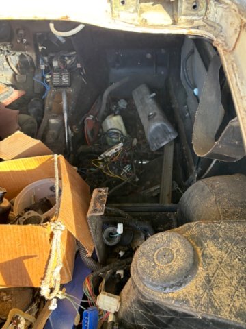
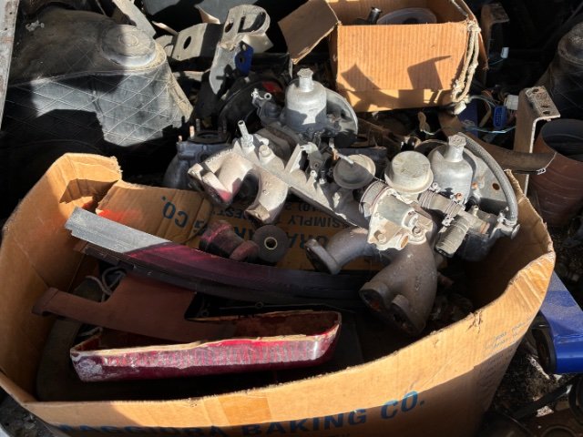
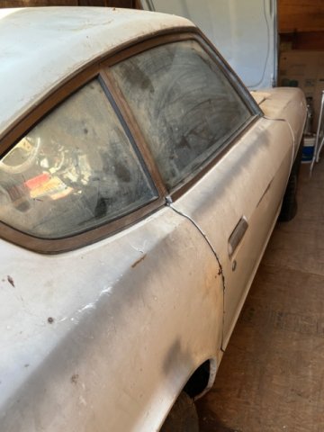
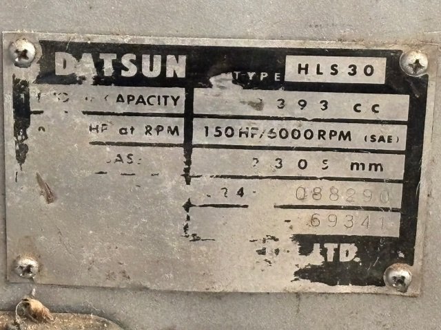
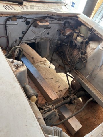
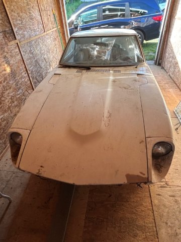
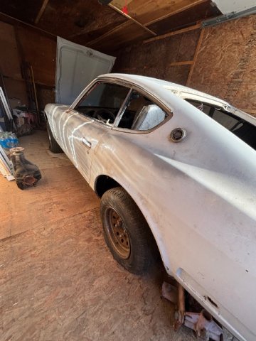
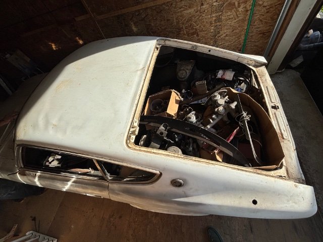
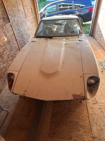
Hello, new user here, I’ve got a 1972 240z barn find, VIN: HLS30-69341, no registration or plates, looking for any interest or suggestions on reregistering non op at the DMV without being the clear owner…will add pics
1 point
-
Sorry, I misunderstood the question. It's a much easier proposition if you're just looking to flip it, IMHO....particularly if you can attract out-of-state buyers. Every state has their own unique requirements for titling and registration, and prospective buyers will (should) know that going into the deal. You will typically have to sell it "below" market value without a title, so be sure to factor that into your decision on how to proceed.1 point
-
Ugh...broken bolts in the block. What a pain. At least the motor was already out of the car! 👍 Making great progress -- keep the updates coming!!1 point
-
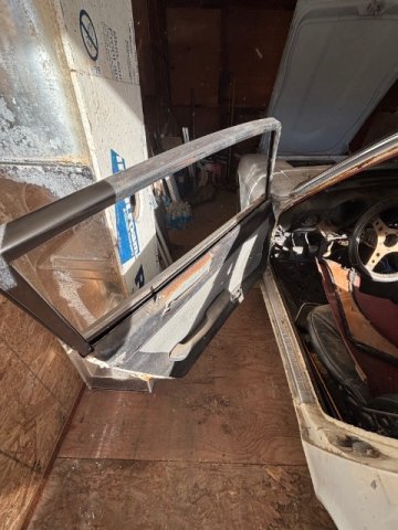
03-16-2026 ATLAS Z UPDATE: My welder showed up today and welded up my cross bracing and a few spots on the trans tunnel where it touches the firewall. While here, he pushed on the outside of the windshield as I pulled the rope and got the windshield in. Tried to get the hatch window in, but it wasn't wanting to do it. So, I will have someone help me with that rear one later. I went ahead and installed my mesh cover for the turbo.....I had to go down a size to clear the engine. I got started on putting the door frames back in and getting the windows working right, more to do on that. PICS:
1 point
-
This whole forum seems abandoned...
1 point
-
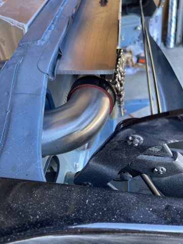
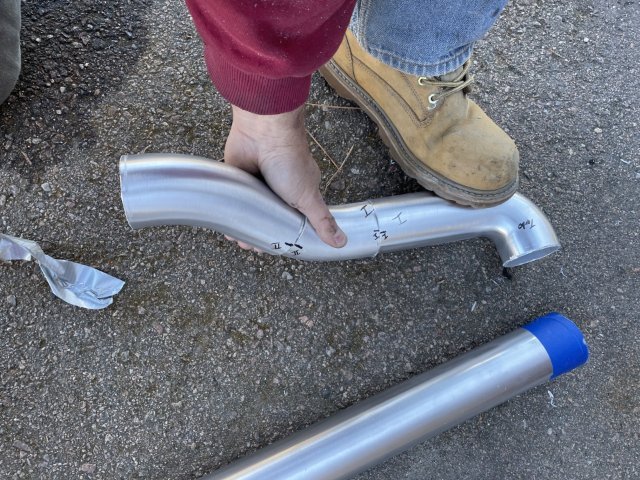
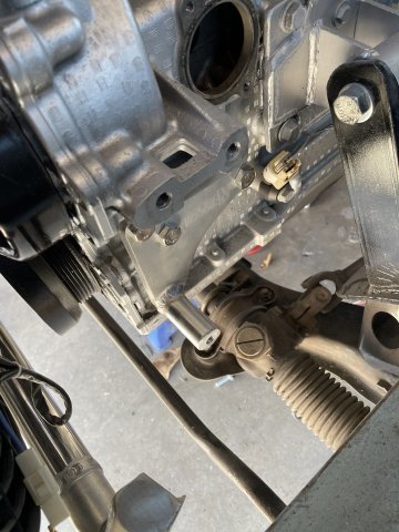
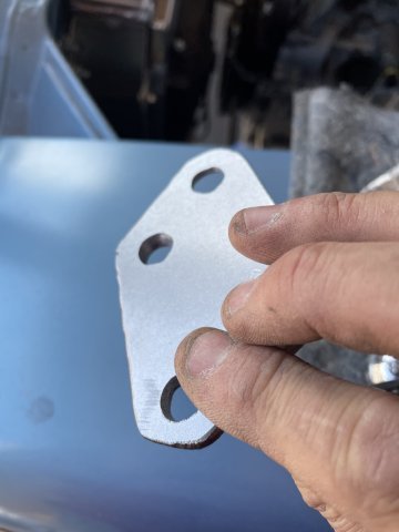
03-14-2026 ATLAS Z UPDATE: Since the intake was off, I went ahead and tackled the project I have been putting off. Modifying the Atlas Industries alternator bracket setup to work on my project. the mounting plate is 1/2" thick, and the alternator just wouldn't clear the frame rail, so after trying to cut the aluminum bracket down, I gave up and traced out the bracket on a piece of 1/4" thick steel and cut it out and drilled the holes out. I then used my Dremel to counter sink the holes so I could use the bolts and everything that came with the kit. I painted the steel bracket with silver engine block paint and the bottom bracket I had to trim 1/4" off of it. Then I was able to install he alternator (brand new AC Delco, nice unit), and then on to the fun part.....belt alignment. Using a straight edge, I had to keep working little by little shaving aluminum off the provided spacer and then lightly grinding the back of the nylon pulley and it turned out great! Then I went ahead and installed the fittings to use a 8AN line for the crankcase breather on the intake between cylinder runners 3 and 4, and I found that by leaving it black it is hidden and you cant see it, so that worked out better than I had planned. once the intake was tightened all down, it was time to finish the intercooler piping. The driver's side was VERY tight. I used two 90 degree sections and trial and error and cutting them down I was able to come up with a decent arrangement. so that piece, to be welded along with a frontal piece to weld a length on to eliminate some couplings were put together and I will take them to get them welded up then take all of the pipes to get powdercoated with the "polished aluminum" finish. I could get them polished.....but it would cost more......opinions? Lastly I put together the intake side, switching to a 4 inch coupling setup with the GM factory style MAF meter. it was 3.75 diameter, so I took some rubber strips that are adhesive on one side and ran a strip of it around the mating surface, and then I was able to tighten the hose perfect on it. I did have to use the 4 inch to 3 inch reducer on the end, as the engine has pieces sticking out that won't allow for 4" pe, etc. I have a 3" screen arriving soon which will be on the front and it should look pretty good. I will have to get inventive to add polished/chromed to it to get rid of too much black. maybe a very thin polished aluminum piece that wraps around it and can be fastened underneath? Anyway, here are some pics:
1 point
-
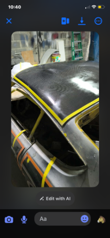
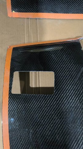
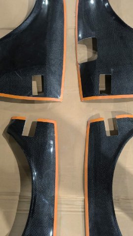
03-13-2026 ATLAS Z UPDATE. A week or two ago, I got with Joshua who runs JP fiber shop and advertises on most of the Z car pages a lot. He is located in the Dominican Republic and makes fiberglass and carbon fiber parts. He made my fiberglass smooth cowl piece. He began a project for me. To make a roof, partial quarters, doors and partial front fenders out of carbon fiber, but just a thin sin.....one that could be trimmed and bonded over existing steel. The idea I have is to make it look like a "Paneled" paint job. Since my 260Z is part american hot rod, part street rod, part sports car, and part Japanese classic, I have used ideas from each genre in this build. To achieve the paneled look, I have had John cut-in, 1 inch around the border of each panel, to include the front fender to door gap areas, and these outlines will be in the factory Nissan #305 light metallic blue, as the cut outs for the door handles and locks, parking lights on the front and rear corners, etc will also show the color "underneath". The body line is the cut off point for the side pieces. The front fenders will remain blue on the tops, with a black windshield frame and top, but a fiber panel is also going on the top. The job is almost completed and then he will mail it to me. I will bond it with the SEM 50 second panel bond epoxy. It is a love it or hate it deal. I fully expect most will hate it/think it looks stupid.....so there's no need to tell me, but I know you will. It is unique....the car becomes "art". here are some pics of the process of making hte panels and a few pics of random cars to show the paneled paint jobs that inspired this. I will be adding my gloss black flares OVER the carbon panels and a black roundel on each door with the number 7 cut out. Click below for video: Main Video 1.mp41 point
-
What will be the main purpose of the car for you? What do you want the car to be? Seeing as you will be installing a roll gage, iMSA widebody kit and an LS big block for I suspect power and torque, you will mainly track the car and won’t be driving on the road. I like your choice of Apex over T3 but that’s my personal preference. But why the Pro Touring and not the Track Attack kit? Also don’t forget the basics of the build like chassis reinforcement, safety features and fuel delivery. These chassis are over 50 years old so if you plan to track and abuse them make sure the basics are good, rust free and reinforced. A good roll cage will do a lot together with the frame sleeves and some bolt on parts but things like seem welding the chassis will also help a lot. VA Engineering over here in the Netherlands has some great pictures on their Instagram of their cages and seem welds. The transform the S30 Z’s into period correct rally cars and yes they do get used like a rally car should.1 point
-
THANK YOU Sir. I am really enjoying this car.1 point
-
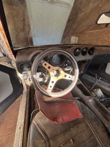
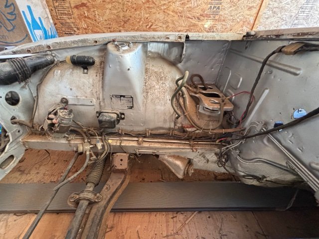
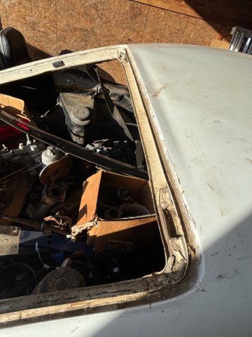
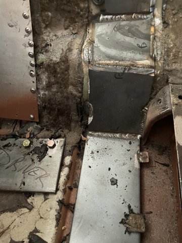
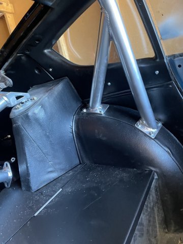
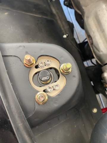
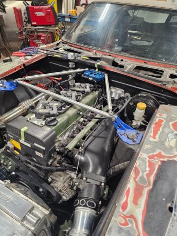
Yes, the front strut tower reinforcement is connected thru the firewall. Attached is a photo that kinda shows it off, these are slightly old pictures taken by the welder prior to taking delivery. Cage has since been finished and had gussets added to the A-pillars. The fender braces from Apex are located inside the front fender outside of the driver cabin. I also have them, not sure if I'll end up using them, cage installer wasn't convinced they really do much other than maybe preventing the front wheels from coming into the cabin during a head-on collision. Plinth location is the deciding factor in how your door bars and subsequent firewall > strut tower bars will/won't interfere with your pedal box. My door bars are pushing right to the outer edge of footwell and angle up from the bottom of the A pillar bar to fit my left if needed. Not sure what pedals you're using but I have a Tilton triple master setup that's going in so the world is my oyster so to speak in terms of pedal placement. This dude's pedal setup looks super neato and I would like to replicate the adjustment mechanism.
1 point
-
Hey Dave, did you have any luck getting a driveshaft done? I had to have a custom one done here in Dallas. I’ll get you the name of the place if you still need it.1 point
-
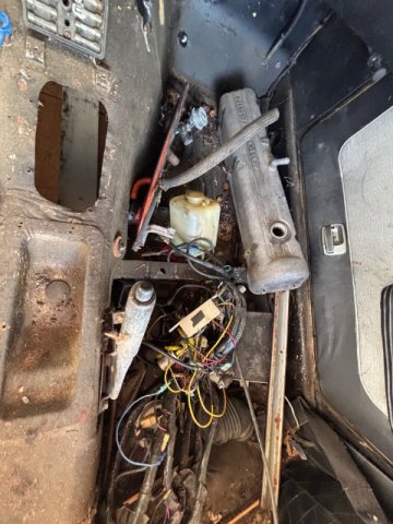
do you have a photo of how the front strut tower bar goes thru the driver side firewall? I'm in the process of finishing up my cage and was considering running a few bars thru the firewall like yours but the driver side has more stuff (clutch master/pedal) in the way for a straight shot. I don't know how tall you are but i stayed just in front of the wheel well for the main hoop and its definitely a bit tight for seat position so up on the rear tube will be helpful for that.1 point
-
You are flying true this! Love to see your progress!1 point
-
03-08-2026 ATLAS Z UPDATE: I got the rollbar in, a little interior painting around those areas, and then I cut the thick steel plates for my "cross bar" section going on the floor from the door jamb right in front of the seats, over the tunnel down the other side and to the other door jamb. Ready for the welder! I also did a little bit of interior parts painting, but the floor plates took quite a awhile. PICS:
1 point
-
Yeah, good point. It's a new feature we're trying out. We're still working out the kinks; so I apologize in advance if you're receiving duplicate notifications. Thanks for the feedback!1 point
-
I liked the email reminder! I think annually would be sufficient.1 point
-
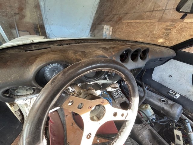
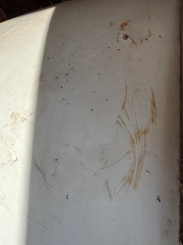
03-06-2026 ATLAZ Z UPDATE. Well, today was Seat Belt Day! When the tub and walls need a cleaning, you go ahead and grab your 52 year old belts, some pliers and duct tape to hold them extended and grab a heavy duty brush, some dish washing detergent and get to it! The water going down the drain was a dark brown soup. Dirt, dust, skin, body oils, everything. You know they never get cleaned. Once dry I will have to paint the housing with the SEM Interior paint, but they will be nice. Oh and the tub is all clean and disinfected with Pine Sol! PICS:
1 point
-
I know how to close the ads 😄. And I don't expect entirely ad free. I do as a user don't want 80% ads though. And agreed there is cost involved, not doubting any of that. There is no such thing as a free lunch as they say. Guess we are all constant problem solvers 🤔. My only thought isn't so much from a how do I block ads, but I know hybridz gets referenced all the time on Facebook groups and Reddit. If I was a new user and didn't happen to have adblock setup, I definitely wouldn't sign up because nothing looked legit. My .02, appreciate y'all listening and I'll go back to my own problems 🤣1 point
-
Tap the arrow on the drop down ad and it will collapse. Then just scroll down. I too lament how prevalent ads are on the internet these days, but Dan has to pay for the server somehow. I like the membership idea. The merch campaigns always bring in a ton of money, but that takes a lot of work from whoever is organizing it.1 point
-
Yeah the broken thread links stink. The pictures might be even worse. I always upload my photos to the site rather than link to a hosting service. Threads that are 20 years old still work great if the poster did that.1 point


.jpg.b34f27553f5960421801c8ab2cbf5db3.thumb.jpg.7889e8073010b6a0d8d6aae0626e768b.jpg)