Leaderboard


Popular Content
Showing content with the highest reputation since 03/23/26 in all areas
-
Been a long week but got everything completely stripped and got some epoxy primer layed down on all the metal surfaces. have plenty of body work to do but atleast its sealed and protected now. Hopefully in the next week or two i can get the bodywork done and get some color on it. I did talk to john and his comment is "I don’t claim to be an expert on bonding. But in my experience cracking at a bond line is often due to inadequate surface prep both the underside of the fiberglass and the underlying metal), poor bonding agent, not enough bonding agent, cheap body filler, and/or excessive flexing of the unibody. On the other hand, I know a lot of guys who do the bolt-on installation. For performance applications, it can be an advantage for working inside the wheel well". With that said I think I will spend the time to make the fitment as good as possible and make a last minute decision based on how well it fits/looks.
 3 points
 -
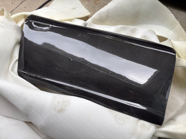
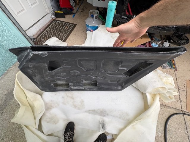
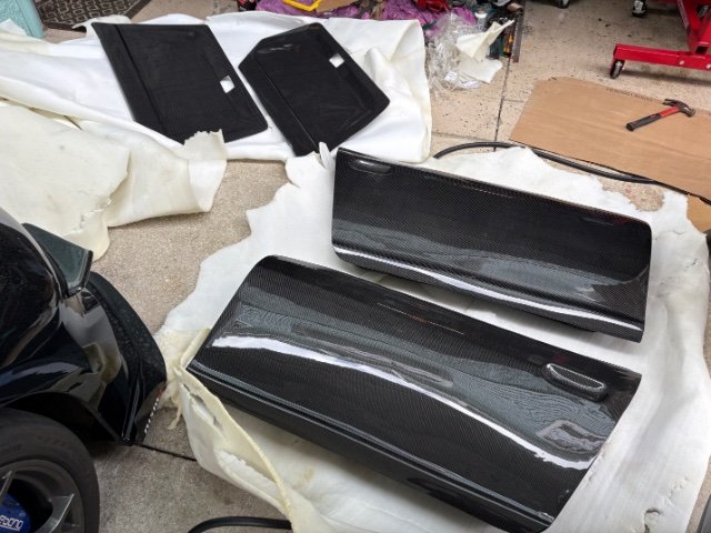
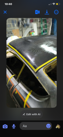
Carbon fiber door and door cards came in, these things are super sexy 🥰
3 points
-
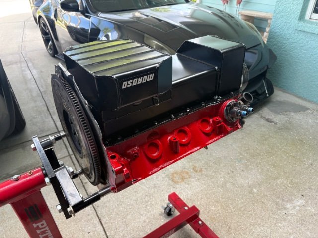
Without the oil cooler, my water temps were never an issue. Never over 200 on track. When I put the Aviaid Mangusta pan on the car it had a provision for an oil temperature sender. Even though my water temps never got too hot on track, once I installed an oil temp gauge, I discovered that my oil temps were getting near 300F. I added the Setrab 34 row cooler, and my oil temps stay below 250F.3 points
-
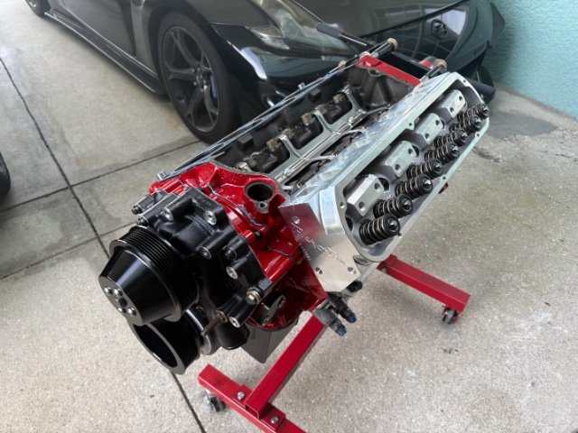
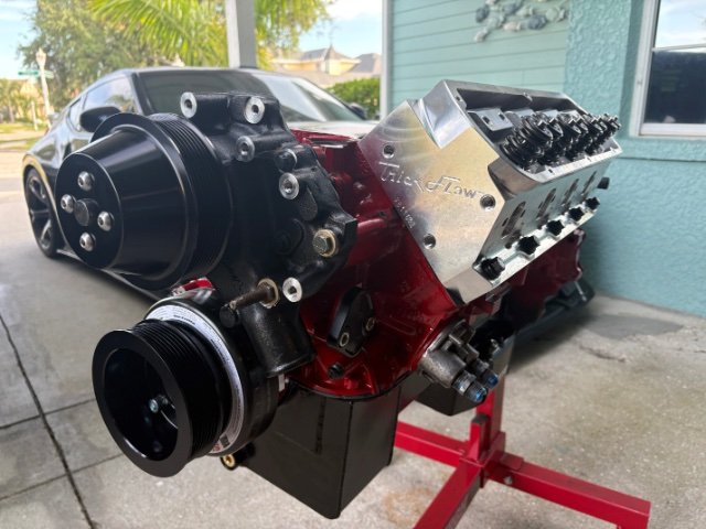
Trickflows are a great choice. I have a turbo 351 so not a direct comparison but when I switched from GT40s to 11r 190s it made a massive difference. Unrelated to the engine. I weighed my stock 280z door today. Its gutted so I can paint them. so no glass, regulator, handle, lock, hardware, window frame ext. just a empty door shell. 34lbs.2 points
-
To wrap this all up, it made 308hp 358lb/ft at 4510RPM 17PSI. Power was climbing the whole time, but it ran out of injector at 4500RPM so I limited all runs to this. More power than expected. Plenty of power for the street, but to be safe I will step up to bigger injectors.2 points
-
waiting on apex engineered LS mounts to come in Tuesday. They sent me some to see how much I need to modify them to make them fit on the LT motor. Then there gonna make some to start offering for kits
2 points
-
spend tons of time last week doing body work. I am TIRED of sanding. Saturday got the whole car in epoxy. Spent 13hr sunday, and 5 hours monday, block sanding and some final little body work touches. Weather got cold for some reason so taking the next couple days to dial in the last of the little details and hopefully later in the week get some color on this thing. I thought i had a good size garage until I need to hang 16 things from the ceiling for painting. A friend let me park my truck at his house. My 240 i just keep moving in and out of the garage. and have the dailies living outside in the driveway during this process.
1 point
-
Back out in the garage this past weekend. I made some progress sectioning in one of the repair panels: I used the new drill press and a hole saw to cut the drain hole in the replacement section. It is a tiny bit undersize, so I will use a die grinder to open it up the last bit to get to the correct diameter. I also used the "shrinker" die that I got from Mittler Bros back before the holidays They were running a Black Friday special. I also used the sheet metal brake I got from them at the same time. I am pleased to be getting some use out of these new tools. I should be able to finish welding this repair section into the right side floor soon. After welding and grinding down the welds, I will be doing some shrinking with an oxy acetylene torch to get the floor panel flat and eliminate any "oil canning".1 point
-
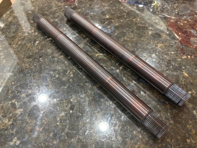
Axles finally came in. Didn’t have much time this weekend, but cleaned the top of the motor and bolt holes and got one head installed.
1 point
-
Fastest s30 IRS timeslip is now 8.38@163.9 mph in the 1/4 mile. Shown are Terrys previous 8.42 timeslips in the same car from different days. https://youtube.com/shorts/KBKmwaQPq6M?si=9UDUJY_FMOOc9f4o
1 point
-
Hello hybrid z, its been so many years since this thread. Im now 46 years old. After reading through my build thread it brought back so many memories. I still have the car (I'm never selling it) it has seen some upgrades through the years gtx3582r turbo, injectors, standalone..etc. the car is still running like a champ and I have never been inside the engine all stock factory toyota. What's most amazing is how reliable the car has been...I think the only major problem i had is when the stock ecu went out.. Things I would like to do in the future are, totally new wiring throughout the whole car, all new fuel system and lines, stainless exhaust system, new dash and seats, new rear suspension setup.( i did the front a few years ago). Reflecting on this build also brings to light how expensive everything is now...in 2008 I paid $2000 for a 1jzgte and r154 trans...today that would cost 6k or more...my z was only $600 running and driving..now, that is about 4k or 2k for a z with trees growing through it... any kind of build like this now us easily 10-15k from the jump.. and thats not counting what you have to upgrade and replace because the car is 50 years old..lol It was and still is a awesome journey! Currently projects (nothing ever changes😊) 84 chevy c10 super charged 4.8 ls engine swap....should be done soon... 84 rx7, s5 roatry engine, ida weber, wide body, 10x17 all four corners😉...
1 point
-
Part 11- trial Fit of the 370 Rear Drive Sewction into the 260Z. In this episode, the Car is finally on the ground for Rear Suspension construction. Since they are using a Fiberglass Hatch Delete section, there will be very little space for anything else but a Fuel Tank Cell. the major problem is time to finish the car as they are not even at the half way point of the build. The craftmanship truly amazing as they solve problems with building a one of kind vehicle. .1 point
-
Front end got tidied up quite nicely and I made new brackets for my intercooler. The drier clears, but I'll have to place the trinary switch on the #6 line instead of the drier. No big deal, but I wasn't able to make the rest of the hoses while I was here. Used on the threaded holes for the original airbox for one of the top brackets, and an existing hole made by the previous owner. The brackets on top aren't supporting weight, just preventing it from tipping forward or back so it doesn't torque on the lower brackets and bend them. Only downside is the brackets look slightly lopsided but the intercooler is centered! Took the car to get aligned and they told me there was play in the steering shaft from a cross threaded bolt. Looks like the end wasn't all the way in and the bolt had never crossed to the threaded side. I loosened everything, chased the threads, and got everything tightened up. Also added one of the missing trim pieces. Looks much nicer. The car as a hole is feeling pretty good, and nearly everything is great. I'm just at a loss with the rear end. I know it'll probably help slightly when I go to the 3.54 rear and everything is rebuilt but there's just this persistent vibration. Flipping the driveshaft 180 somehow solved most of it, but I still get the occasional buzzing and it's driving me crazy. I'm about ready to go back to the stock control arms, oem spindle pin, stock mustache bar, and a kameari mount on the original front diff crossmember. Everything on the car just feels so great except for the rear end buzzing or squeaking. So much of the car is damn near perfect that the small issues like that are a distraction from enjoying it as much as I could. Alignment rescheduled for today, so we'll see what they find or if it solves my problems.
1 point
-
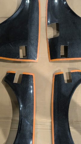
Those are incredible. I'm with Mitchel on needing to know the weight difference. You gotta put them on a scale for us. Very interested in fitment and your thoughts along the way. They look like they allow for roll up windows and factory door handles too. very nice.1 point
-
On my car, I am using the SN95 timing chain cover, water pump, and pulleys. By doing so. I have a couple of extra inches of space at the front of the engine.
1 point
-
I should give him a call. I've talked to him several time when buying the parts. I read the PDF off ztrix site to a body guy and he was not confident in the success. but John may have some better ideas.1 point
-
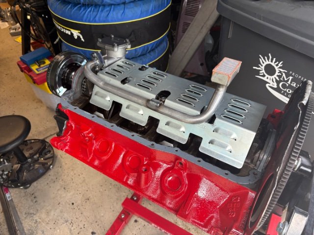
Screw up fixed, new oil pan is on. Had to modify windage tray for rear pick up to fit. Started on the harmonic balancer, not sure it’s on all the way, hopefully I’ll get a little more time tomorrow.
1 point
-
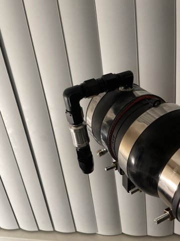
Committed to new tires. Far less weight to balance them as expected. The inside was more worn than I realized on the old ones. Went with Yokohamas in 205/55/15. Skinnier than I wanted but they were half of what the 200tw options were, weren't so aggressive, and they'll give me a couple more years of use before I spend bigger money to go up a size. Currently working on getting the AC condenser and drier mounted with the new hardware from vintage air. I'm hoping the drier JUST clears the intercooler, but I'm anticipating it being tight. Will be making new lower brackets for the intercooler as well. You can see in the pic they're extremely bent because they were so flimsy. As they say... Nothing is more permanent than a temporary solution.
1 point
-
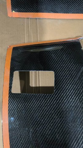
03-25-2026 ATLAS Z UPDATE: I got some of the fittings in I need for my crankcase pressure to catch can to intake setup. Also tall of my carbon fiber panels have been cut, final polishing on roof section then ready to ship to me and bond them on! Then make the borders shiny!
1 point
-
What oil pan are you using? You'll have to set the motor back really far to get a front sump pan behind the front crossmember. I'm using an Aviaid Mangusta pan on mine and I needed a custom crossmember to get the front sump to clear.1 point
-
My efforts to get this other Z back running have expanded quite a bit beyond the rebuild of the 3.0 stroker motor. At the moment, I am working on repairing some rust in the floor panels. I have been watching a number of "Make It Kustom" videos on Youtube by Carl Fisher. In one of them, he creates some forms out of 3/8" plate to create a "hammer formed" part. Additionally, he uses a hydraulic press to "stamp" a recess into the battery tray he is making in the video. The rust in my floors on this car is not extensive. It is generally in the area of the large oval depression in the floor panel (on both sides of the car). Yesterday, I spent a few hours cutting out and grinding/filing on part of the form I plan to use to replicate the depression. On the right side floor, I only need a small portion of it. On the left side, I will attempt to make a full piece to replace the depression. I've never done anything with forms likes this, so we'll see how it goes. I will be using my 12 ton press because it is what I have to attempt to make the replacement part. But, I have been watching facebook for a suitable upgrade, perhaps a 30 to 45 ton press.1 point
-
It's been one of the busiest years of my life but the turbo build continues in the background. Since the last update, the circuitry has been mapped out so I visited the chassis to start installing the mil-spec bulkhead and radlok connectors. Generally, the plan is to run Haltech for ignition control, knock detection, etc. and ditch all piggyback systems which I'll probably recycle on another ongoing turbo project. Only the best for the Z 😉. The resto shop is doing a fantastic job with great attention to the details. They've installed the sweet Capital Metal Works full length framerails and started massaging bent OEM sheetmetal back into shape, along with continuing to metalwork other detailed aspects of the chassis.
1 point