Chickenman
-
Posts
1051 -
Joined
-
Last visited
-
Days Won
9
Content Type
Profiles
Forums
Blogs
Events
Gallery
Downloads
Store
Everything posted by Chickenman
-
New project-reducing bumpsteer
Chickenman replied to RebekahsZ's topic in Brakes, Wheels, Suspension and Chassis
You may want to re-think the no rear bar setup. A rear anti-roll bar actually increases the straight line stability of a car. And with a high CG like you have, you want as much roll stiffness as possible. The front bar alone can't do all the work. Side winds are one area where a rear bar will really help with car stability. Even the stock one would help. But a 7/8" would be better. You're not turning corners, so don't confuse the oversteer/understeer balance issue associated with turning corners like in Autocross. On a Landspeed Attack car or Drag car the Traction Circle is only limited to a straight line. There are no, or minimal cornering forces generated. Running on Highways can pose problems. A Highway has road crown and dips and wallows. Additional roll stiffness will really help the car maintain a level attitude on uneven roads. Dragstrips and Airport runways are better... but Airport runways can often have gusty side winds. Add side winds to a high CG and you have a white knuckles experience. Edit: As a side note. A few years ago I helped " Heavy Chevy " at ThirdGen.Org set up his 1988 Camaro Super Stock car. He always ran it with no rear bar and car was inconsistent launching. Addition of a rear anti-roll bar transformed the car and it launched dead straight every time after that. Production based Drag cars that lift their front wheels on launch need a rear anti roll bar. Rear springs alone are not enough to handle the body roll. Front anti-roll bar does nothing when the wheels are off the ground. IRS cars are better at launches than Beam axle cars, but there is still Torque induced roll present. A proper Racing Four link or Three link design is a different ball game.. but production rear suspensions have big compromises. -
I'm thinkin' it's pretty retarded and way out of spec.
-
Correct... Because the Crank sensor can usually be physically adjusted ( IE: as in a 36 - 1 wheel ) there has to be some way to let the ECU know where the Crank sensor is in relation to TDC. Being that the MS is a Universal ECU and used on hundreds of different engines. Once you have the Trigger angle setup and matching, remember to " Unlock" the Trigger Angle check box and cycle the Ignition switch. Then MS will be able to use the programmable timing table.
-
1985 300ZX Optical Dizzy has four connections. You also have to connect the +12v feed or no worky. For Batch Fire Fuel injection and a single Coil you need Crank signal, +12v and sensor ground hooked up. For vsequential Fuel Injection and/or Coil On Plug ignition you also need the Cam sensor connection. Baggedgods: I sent you a PM with pictures of my 280ZX Turbo Dizzy wiring. 300ZX Dizzy wiring is the same ( Optical modules are interchangeable between L28 Turbo Dizzy and VG30E dizzy ) . Did you get it? Also check Post # 50 for setup for Sequential Injection. Click on Thumbnail. PM me if you want to do some Online tuning and setup like we did before.
-
Instead of heat with a Torch, a safer alternative is one of the new Freeze Penetrating sprays. CRC makes a good one. They cool the part to approx -30F, shrinking it and allowing penetrating fluid to Wick in. Works great on Diff housing plugs and Trans housing plugs. Worked fantastic on my Audi with a badly seized diff fill plug. Be sure to apply a small amount of Never-seize to the plug when you re-install it.
-
I used Z Creations wiring method and did not have to use an extra Diode. I believe most modern IR alternators already incorporate circuitry to make sure that alternator field output is killed when an Ignition switched 12v source is used .
-
280zx turbo ignition control module swap
Chickenman replied to rickyellow zee's topic in Ignition and Electrical
Personally, I'd stay with the Matchbox Module ( E12-80 ) . Much newer technology and they put out a much more powerful spark than the Transistor boxes on the 280Z. The 1975 and 1976 boxes are the worst. Not much more spark energy than stock points system. On " the 510realm" we have Turbo cars pushing 18 lbs of boost on the Nissan E12-80 module with no spark blow-out. Nothing wrong with that!! If memory serves me correct current draw on the 75 and 76 boxes is only 2 amps. That pretty wimpy. I'll try and find the specs on the E12-80.. 4 amps seems to be ringing a bell. -
Running an F54 block and Flat Tops with N47 head. 10.3 to 1 CR calculated. 34 Degrees total Mechanical Timing ( 14 degrees static and 20 in the Dizzy ) . Vacuum advance modified to 15 degrees total. Edit: Unknown if head has been shaved or how much. PO build... and his specs are suspect. OK on Shell 91 or 92 Nitro. Had an issue recently where engine detonated under high load with Chevron 94 ( BC Canada ) . Never had that happen before. But Turbo guys have been complaining on and off about Chevron 94 in BC for 2-3 years now. 1: Gasoline quality plays a big part in ignition timing. Golden rule: When in doubt... take it out. Better to be a couple of degrees under perfect timing than a couple of degrees over. Modern knock sensors allow Manufacturers to maximize Ignition timing ( aggressive timing curves ) and that increase HP and Fuel mileage. Of course we don't have knock sensors ( stock ) 2: Ambient temp plays a big part. What works in the PNW may not work in California, Florida or other Southern states. YMMV 3: Cooling. You must have a PERFECT cooling system. L series engines don't like to run hot or even hottish. In Southern states a 160 degrees ( Tropical Nissan Thermostat ) seems to be the ticket. Tony D reported that the actual cylinder head temperate at #6 cylinder runs about 20 F higher than what is seen at the Thermostat housing. AC puts a big Toll on cooling system... but I can't drive without it. Strangely enough. The annual summer Temps in the PNW are regularity in the 90's for the last few years ( Lower Mainland BC ) . Supposed to hit 35C ( 95 F ) in Metro Vancouver today. 32 degrees mechanical total may be a safer bet in really hot climates or with iffy fuel..
-
Forged piston are used in Turbo cars because they are much more stronger than cast pistons. The pin boss take a lot of load with Forced Induction engines and forged pistons are much stronger in this critical area and also in the dome. They are also able to handle detonation, Torque and shock loadings and high combustion temperatures much better than cast. Forged pistons can withstand loads that will shatter cast pistons. RPM is not the really big problem on Turbo motors. Torque load is. On VW.Audi 1.8T engines guys can bend stock rods at 3,000 rpm. New technology Turbo's ( BB and Hybrid ) with quick spooling can easily build 20plus lbs boost by 2,500 RPM these days. Forged pistons are a very good investment on any Turbo engine boosting over 10 psi.
-
Clutched pulleys? What are you referring to?
-
Couple of other tips to help you out. the old alternators have a " T " terminal. The horizontal connection is the Sense wire. Also called an N wire or sometimes IGN wire. The Vertical connection is the Lamp connection. Also called F ( Field ) connection. Here is a chart for the different types of alternator connections. Our Datsuns are a Type 1. The 1985 300ZX Mitsubishi alternators are a Type 5. Note these are viewed as looking at the end plate of the alternator.
-
Go with a newer style Internally Regulated alternator. Spinning an alternator faster does not increase the maximum overall output and can blow the windings off the rotor at high RPM's. More modern and efficient alternators generate more output at idle by design and that is the way to go. I used the 1985 300ZX 70 amp alternator and it works great. Remy part # 14655 from Rock Auto. It's a smaller frame Mitsubishi style. You could also use an 80 amp 1985 Maxima alternator, but you may have to switch pulleys. The Mitsubishi uses a different type of connector than our Datsun Z cars. . Mazda uses the same type. I went to the Autowreckers and snipped one off. Common on Mazda Protege, Miata's and other models. I used Deutsch DT connectors to connect the old and new alternator harness together. On the V/Reg side there are two ways to connect the wiring. I prefer the Z Car creations method as it connects terminals 1 and 5 and 3 and 6. Atlantic Z Cars method connects 1 and 5 and 3 to 2. the difference between #6 and #2 is that #2 is a constant +12V from the battery and #6 is a switched ( Ignition ) +12v. Using the switched connection assures that the alternator stops charging when the ignition is shut off. http://www.zcarcreations.com/howto/voltreg.htm I just used the above connection method on my 1976 280Z and it works great. Nice to have the reliability of an Internally regulated alternator with modern Solid State components instead of the old mechanical V/Reg and it's 40 year old technology. I previously had a new 60 amp ER 280Z alternator on the Z. But the 2 year old mechanical V/Reg started to act flaky on a recent trip.
-
What is the dead time for this injector????
Chickenman replied to Turbo260Z's topic in Fuel Delivery
1.2 to 1.5 ms ( At 13.5 volts ) is good starting point according to RX7 forums. Edit: That seems pretty laggy to me. I would expect more in the range of 1.0 ms. I've also found documentation as low as .75 ms dead time with the Low Impedance 195500-1370's. Regardless, the IDT is just a starting point and has to be fine tuned per the ECU drivers. Might be better to post this up on the MS Forums. Someone there probably has an answer at their fingers tips. Edit: This seems to be quite helpful: http://www.msextra.com/forums/viewtopic.php?f=134&t=49918 -
Off centered 75 280z steering rack....hmm
Chickenman replied to marinez's topic in Brakes, Wheels, Suspension and Chassis
Steering wheel has probably been removed at some point and not indexed correctly. There should be an index mark on the top steering of the steering shaft that points to 12:00 O-clock when rack is centered. Get that mark pointed straight up. Install your steering wheel so that it is level, and then adjust your wheel alignment. -
TB before IC? Done all the time on Turbocharged V8 engines. Short run to IC is the key as you mention. Nice design you've made!! Nelson racing engines build a Ton of BIG HP Turbocharged motors using Air to Water Intercoolers. Have a look at their combination AW Intercooler and Intake manifold combo for LS1 engines: http://www.nelsonracingengines.com/~nelsonra/the-gallerry/Dual-Injector.html
-
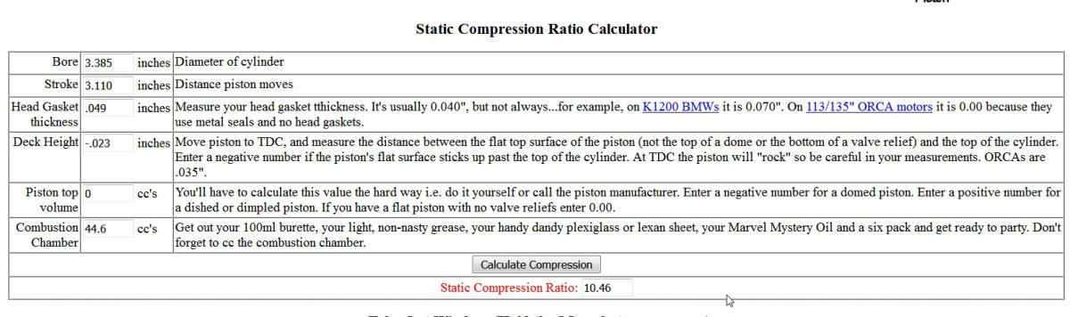
Here's an updated calculation using the stock head gasket thickness of .049" ( 1.25mm ) and a positive deck height of .023" as measured by Braap in the article. This makes a lot more sense. The P79/P90/P90a heads used on late motors with the F54 an has a big combustion chamber of 53.6 CC. Compare that with an N42/ N47 head with a 44.6 cc chamber and you can see why you have issues with detonation with the N42/N47 heads. 10.4 to 1 CR is hard to do on 91 Octane pump gas. Add a less than optimal chamber shape, and it's ping-a-ling city!!

-
Could be the deck height?? The Oz calculator sticks the deck height at .050mm ( below the top of the deck ) . Calculator does not seem to allow that value to be altered. Was recently reading an article that the L28 Flat top pistons are .025 mm above block deck . I used a different CR calculator that does allow deck height to be adjusted, and setting it at -.025mm ( -.10" ) gives a CR of 10.3 to 1 with flat tops. Confusing. https://www.rbracing-rsr.com/compstaticcalc.html Edit: Found one of the the articles on deck height. It was on Hybrid Z of course. Check out Braap's post at #5. There are also numerous reports that Frank Honsowetz's Datsun Bible has several errors in it pertaining to Piston heights. http://forums.hybridz.org/topic/58658-pistiondeck-height-misinformation/
-
Thanks. That's a great mod!! That little Microswitch is a PITA. Living in the PNW we need all the help we can get with defrosters. It would also work on Bi-Level, which means It can blow cold air into the drivers foot-well with the manual floor vent. Kool!!
-
I've noted that the OZDDAT calculator comes up with figures that are different from other established sources, including Hybrid Z. EG: I punched in an L28 with Flat-Tops, stock N47 head and stock L28 head gasket. Calculator came up with a 9.7 CR. However, most other sites all report that combo as being over 10 to 1 CR. Usually in the mid 10's. That's quite a difference.
-
Rock Auto has ITM flat tops for L28 for $34.78 USD each. Available in standard sizes and over bores. Just order 6 and be done with it. Rock Auto ships worldwide Order for a 1983 a non-Turbo 280ZX . These are flat tops. http://www.rockauto.com/en/catalog/nissan,1983,280zx,2.8l+l6,1209394,engine,piston,5620
-
Camber change after 1.5" drop?
Chickenman replied to mtnickel's topic in Brakes, Wheels, Suspension and Chassis
Either way you do things, by relocating the inner pivot point for the LCA by drilling the X-Member, or by relocating the outer LCA pivot point and steering arm with a spacer, the amount you re-locate either pivot point is going to affect the amount of bump steer experienced . You could use different thickness of spacer at the outer pivot point or a different height of hole drilled on the X-member and end up with different amounts of Bump steer generated. Are we agreed on that gentleman? That's why modern suspension point calculators are so handy these days. -
Camber change after 1.5" drop?
Chickenman replied to mtnickel's topic in Brakes, Wheels, Suspension and Chassis
I think we're saying the same thing, but it is a difference in semantics. On a lowered car with no other changes, you often see an increase in Bump steer " amount" because the geometry change has now moved the steering arm into a poor region of the curve. Using bump steer spacers does not change the curve shape as you say, but it does lower the steering arm, putting the bump steer plot point back on or close to the stock design point on the bump steer curve. So in that respect, it does improve the bump steer situation over a stock LCA positioning.....on a lowered car At the same time the Bump steer spacer will alter the roll center. Moving the inner pivot point upwards does not change the position of the steering arm point on the curve but rather changes the shape or axis of the bump curve line. Hopefully into a shape that is more advantageous. A change in either the inner pivot or outer pivot, will both affect the amount of bump steer. Either method can be used and either method affects the parallelism between the tie rod linkage, the LCA and the steering arm. Not saying one method is better than the other, just that both methods will affect the amount of bump steer generated. Are we agreed on that gentleman? -
Camber change after 1.5" drop?
Chickenman replied to mtnickel's topic in Brakes, Wheels, Suspension and Chassis
Quote from Whitehead Performance: https://whiteheadperformance.com/1971-datsun-240z-restomod-front-suspension-and-wilwood-front-brakes/ -
Camber change after 1.5" drop?
Chickenman replied to mtnickel's topic in Brakes, Wheels, Suspension and Chassis
We'll have to discuss this further, but I'm rushing off to a Birthday party right now. Since it's a bunch Road Racers and Autocrossers, we will have a topic for discussion. However, as you state Jon ( and I've quickly read in the Bump Steer FAQ ) , the use of these " Bump Steer spacers does bring the Bump steer curve back into line with the stock curve. However perfect or imperfect it is. As the spacer goes between the strut and the steering arm, both the steering arm and the LCA outer end are moved downwards. Does that not alter BOTH the Roll center and the Bump Steer Curve ( after lowering a car ) . It has to does it not??? Discuss and I'll be back later... -
Camber change after 1.5" drop?
Chickenman replied to mtnickel's topic in Brakes, Wheels, Suspension and Chassis
Delete..see below.