jhm
-
Posts
1413 -
Joined
-
Last visited
-
Days Won
28
Content Type
Profiles
Forums
Blogs
Events
Gallery
Downloads
Store
Everything posted by jhm
-
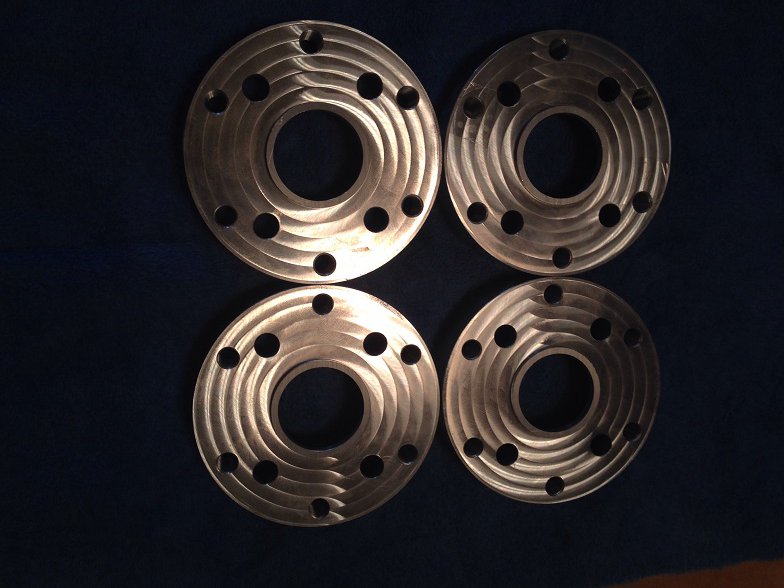
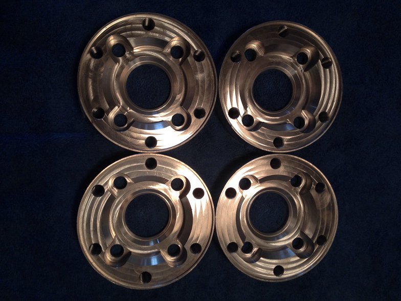
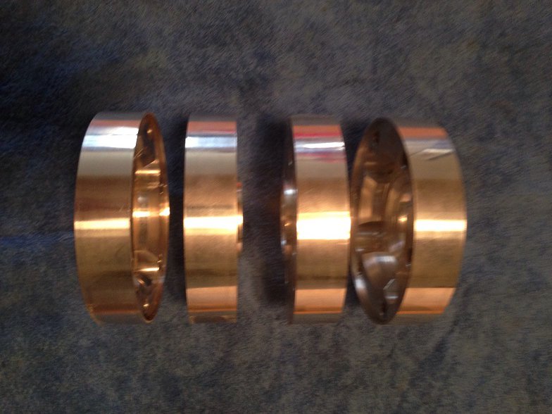
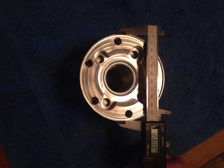
One complete set of billet aluminum CV adapters, to convert your half-shafts to CV axles, made by Mattndew (on the510Realm). Brand new, never installed. These are for the 930-style CV joints (108mm). Four adapters total, to convert both rear half-shafts. Thanks for looking.

-
BUMP
-
Historic/Vintage Race Standard Brakes
jhm replied to 260DET's topic in Brakes, Wheels, Suspension and Chassis
Hey Miles, have you had any noise, chatter or squeal issues with those Carbotechs? I'm currently running the Porterfield R-4S and am reasonably happy with them, but always willing to try something new. Mostly auto-x and track use, but the R4's were driving me nuts when cold. Thx. -
Sale pending....
-
best adjustable coil overs for daily driving?
jhm replied to bawfuls's topic in Brakes, Wheels, Suspension and Chassis
Apples and oranges. With the GC sleeves, one removes the stock spring perch and welds on a new perch ring for the provided coilover sleeves (kind of the standard coilover installation). The Cosmo sleeves sit on the stock spring perch, and are shorter than most coilover sleeves, which is why the others have pointed out that ride height adjustability is limited as compared to other coilover conversions. If the Cosmos meet your needs, however, go for it....you can't beat the price. Here's a pretty decent step-by-step write-up on the Cosmos: Cool project, BTW. -
best adjustable coil overs for daily driving?
jhm replied to bawfuls's topic in Brakes, Wheels, Suspension and Chassis
The BCs have a nice design that allows one to adjust ride height without affecting suspension bump travel...this makes them an attractive option for a daily driver that will see a lot of varied road conditions. -
This guy usually has several in stock, and his prices are usually pretty good....he advertises on several of the Datsun FB pages: Alexxi Cini The Classic Zcar Club about 3 months ago Selling Subaru STI R180 + R160 differentials Ottawa, Ontario $650 Fall Special ! Selling Subaru STI R180 + R160 differentials, message me for a shipped price to your location. STI R180 LSD 3.54 Torsen $650 STI R180 LSD 3.90 Clutch Type Plated $650 STI R180 LSD 4.44 Clutch Type Plated $825 - The R180 4.44 will give you the quickest acceleration of all the R180's, very hard to find, Japan only STI R160 R160 VLSD 4.44 $120
-
Glad you chimed in, Fritz. I think it's great to have some new options here; so thanks for bringing these into the market!
-
I am not aware of any manuals that contain this level of information, Joost....but that would certainly be nice. I just emailed you a few minutes ago -- tracking info shows the package was delivered yesterday.
-
Checked some spare parts lying around in the garage. 😜
-
Joost, you are correct...12x1.25. Cheers
-
Well done, Sir....and kudos to you for saving another one from the crusher!
-
Would it be easier to stay with zero offset and dial in some negative camber? That might preclude the need to roll the fenders, while still giving you the clearance you need on the inside of the wheel. Also, if you're averse to switching to coilovers, the stock spring perches can be trimmed for additional wheel clearance w/o affecting the structural integrity.
-
There are a few good threads in the FAQs regarding OBX issues and installation. Check 'me out, if you haven't already done so, and they should answer most of your questions. Seems like OBX units are NLA for the R200, so this was a good find for you!
-
My pleasure, Joost! Good luck with the rest of your build. 👍
-
Actually, the stub axles are often the weak link in the drive train vs the diff and half-shafts. I'd hesitate to give an actual number limit, because it depends on so many variables. If you can provide some specifics on your build and setup, might be able to better answer your question.
-
Found this thread on one of the 510 forums....I don't know Fritz personally, but he seems to be quite a regular in the "Dime" community. http://www.the510realm.com/viewtopic.php?f=12&t=31253
-
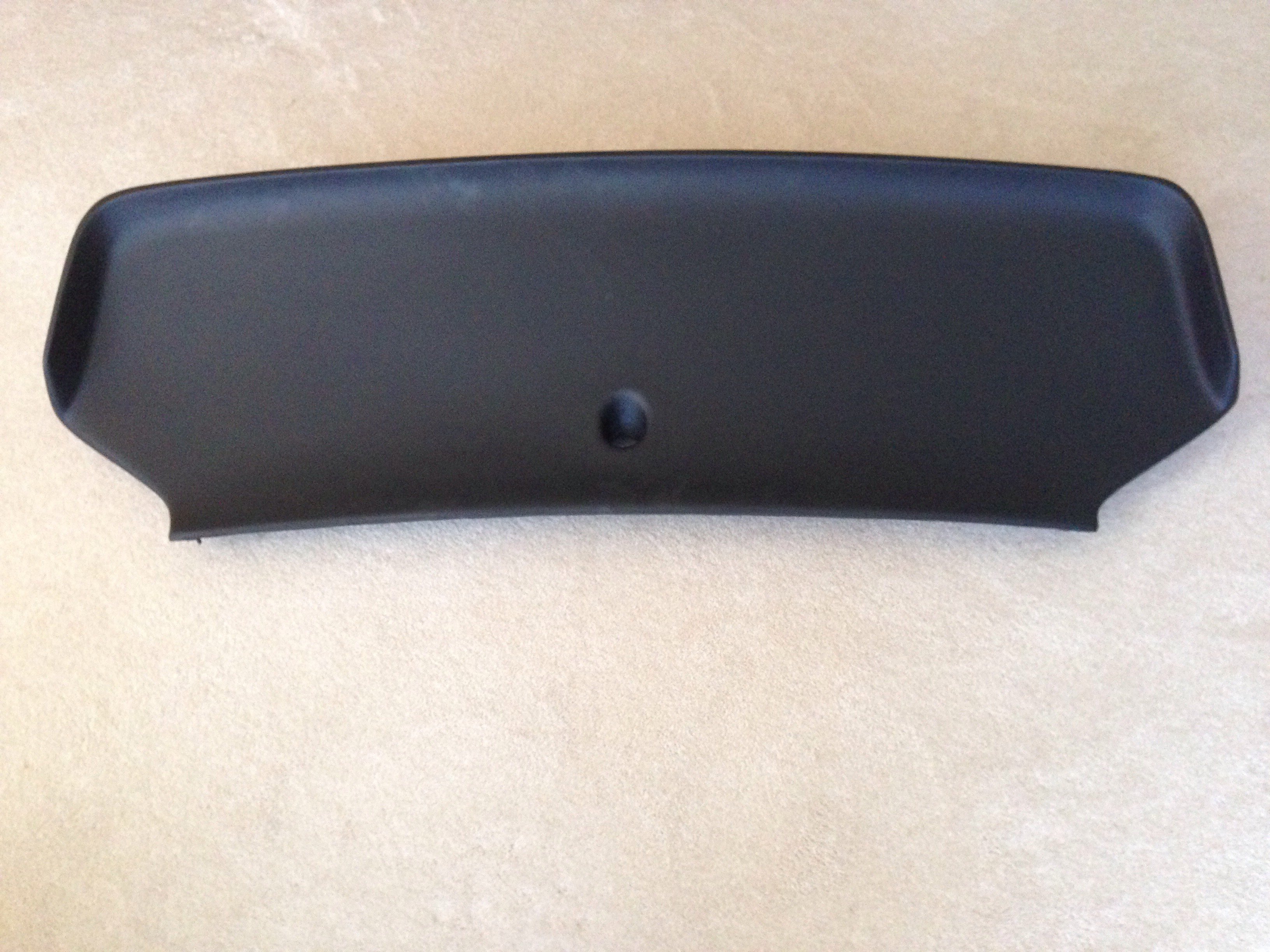
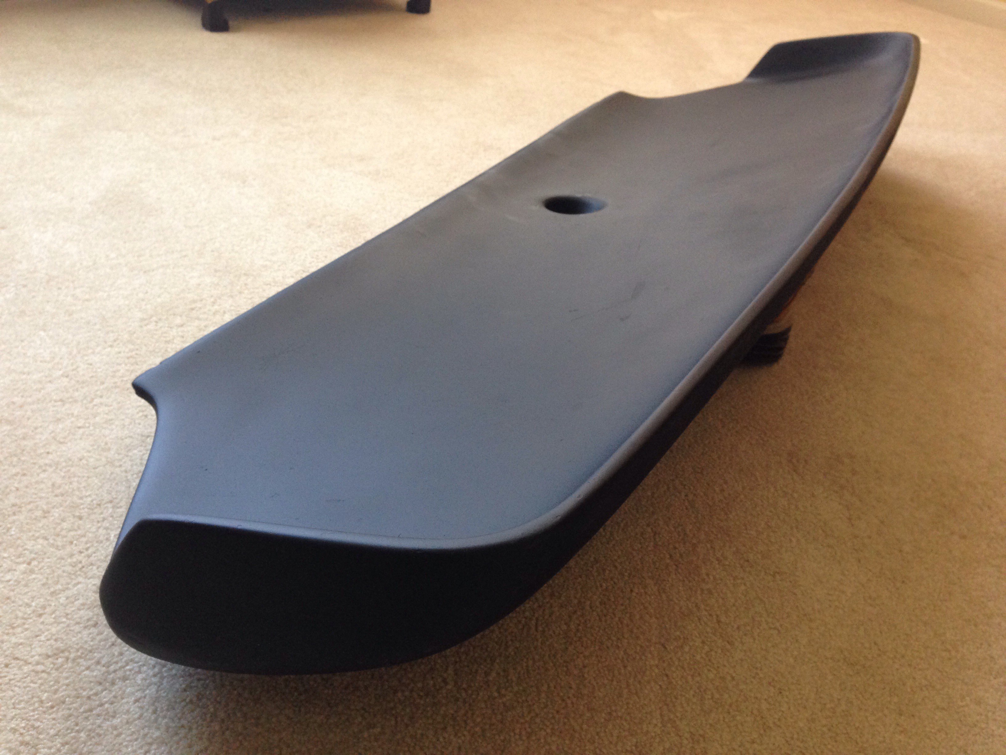
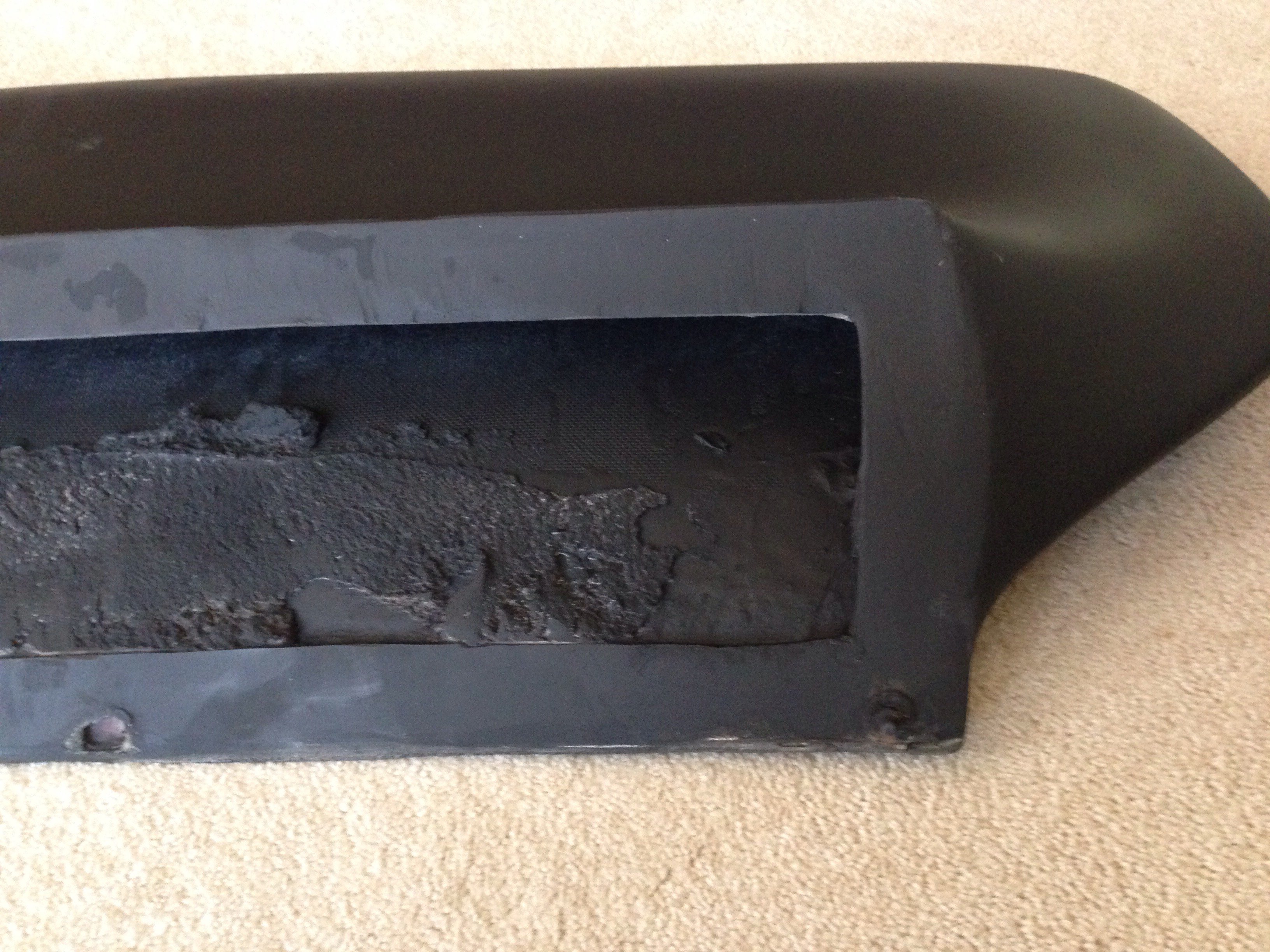
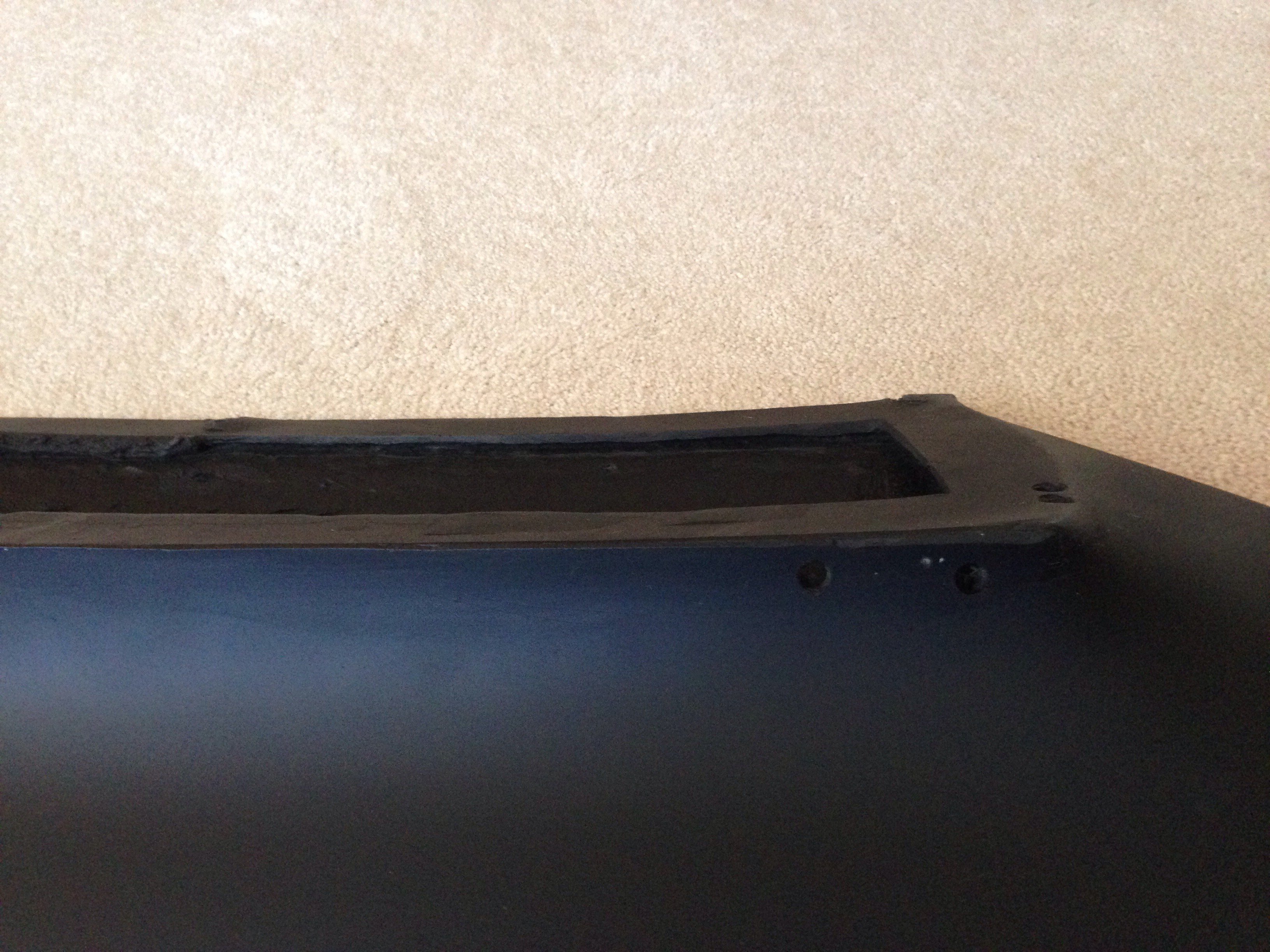
One original fiberglass whale tail for sale. These are becoming really hard to find these days. The mounting face is kind of buggered up, but the shell is in surprisingly nice shape...no obvious seams, splits or cracks that I can see. Most people fabricate their own brackets for secure mounting, and often fully mold the tail onto the hatch with fiberglass. Several pictures are included to show its condition as clearly as possible, but I am happy to take more if necessary. No idea if it's a JCR tail, or some other manufacturer -- there are no obvious stampings or labels to indicate its origin. Shipping will not be cheap for this big package. Assume $100-$175 for most U.S. locations via Fedex or UPS; possibly cheaper with a shipper like Greyhound, if that's an option for potential buyers. $150 plus shipping. Thanks for looking.
-
These are intended for use with aftermarket coilover sleeves and top hats. The stock springs are significantly larger (both diameter and length) than these. If you are looking to lower the car without converting to aftermarket coilovers, I would suggest looking at "lowering springs"....made by companies like Eibach, Vogtland and Tokico.
-
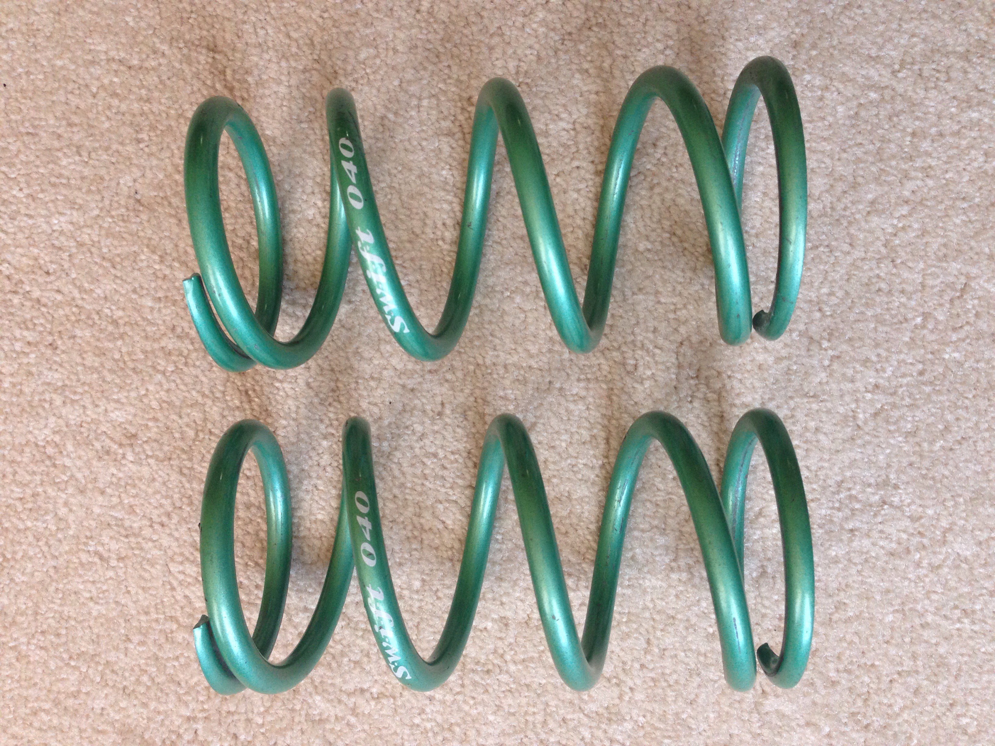
One pair of used Swift springs, lightly used one year in the off-season for street use. Still in excellent condition. 7" free length (178mm); 2.75" inner diameter (70 mm); 224 lb/in (4 kg/mm). These are universal coilover springs that will fit any strut setup that uses a spring with 2.75" (70 mm) ID. The Swift part number is Z70-178-040. $85 shipped anywhere in the U.S. Thanks for looking.
-
Was thinking along those same lines, Jon; so I contacted the owner to get more info, and received a really fast/comprehensive response to my email. Copy of text included below FYI.... ---------------------------------------------------------------- John Meyer 9:58 AM (9 hours ago) to fritz Hello Fritz- Someone referred me to your company the other day as a new source for CV axles, and I have to say I'm impressed with your product line! I'm currently running an Sti R180 in my 240Z, and I already have aftermarket machined side axles, so I would primarily be interested in your "CV axle set - Datsuns with stock differential". Can you tell me which CV joints are used in those axles? Are they OEM Subaru CV joints? And if so, is that the source of the recommended torque limit of 225 ft-lb? Just curious.... I had previously planned to fabricate my own CV axles using 930 CV joints; but I'm always looking for new options, so I may very well be contacting you to order a set of yours. Is there a long lead time for these units once they're ordered? Thanks very much, and I wish you the best of luck. They look to be very nicely assembled units! r/John Meyer Datsun RestoMODS 10:47 AM (8 hours ago) to me Hi John, Glad to see you liked what you say and the fact that you were referenced here. The CVs are not Subaru. I'd rather keep the R&D quiet for now but I can say that these axles have larger housings than the STI and the axle diameter is also ~1/16th thicker. These CVs are beefy and although I've listed the OEM 225ft/lbs limit (more to keep anyone from trying stupid stuff that would break just about anything) I will be mounting them on my VQ37VHR 280z when it's complete. I have several customers with close to 300 ft/lbs engines as well. Finally, the CVs are brand new, the highest quality I can source. The axles are not cut or resplined, modifications are exclusive to the housings. The goal for this business is to give back to the Datsun community. I do have a well paying day job so the axles are priced to cover costs and provide just enough cushion for R&D on new & unique products (wait until you see what's coming down the pipe!). As a result, it's been flat out building CVs - pretty much the reason why marketing has been minimal in the S30 community right now. I'm unable to build any surplus stock, a good problem I guess. My suggestion would be to place an order as soon as you're ready. Anything ordered today will be shipping early the week of February 11th. Sorry for the long reply, I like potential customers to have full transparency. Please don't hesitate to contact me if you have any other questions. Fritz
-
Yeah, I have the same questions. I made the decision a while ago to switch to CVs once my half-shafts started crapping out. After 5 years of problem-free race-use, I'm still waiting for that to happen (but I'm only making moderate power, so it may still be a while). Still nice to see new products being introduced for our 45 year old vehicles!
-
So I'm a little embarrassed here, but I came across what I think is a new source of CV axles the other day. Has anyone else seen/used these before? https://datsunrestomods.com/collections/all They offer some pretty nice bolt-in CV conversions for both stock R180 and Subaru R180, and their prices seem better than most other vendors. The one obvious downside is the recommended torque limit of 225 ft-lb (possibly because they're using stock Subaru cv joints?) I've contacted the vendor via email to gather some technical background, and may very well be ordering a pair for myself. Would be interested to hear if anyone else here has information or personal experience with this company. Thanks!
-
HybridZ has ALWAYS been my first go-to place when I've got a technical question or new idea in mind. And as much time as I've spent digging through the site, I can always find new and interesting discussions that I've never seen before. (And like several of you have already noted, my typical response to a question on FB is to post a link to the thread on HybridZ that answers their question.) Can't thank everyone enough for all the many contributions over the years!!
-
In addition to everything you listed, grannyknot, my impression has been that the 280 shells use thicker gauge steel in several areas than the earlier year shells. I can even see the difference in sheet metal thickness in various areas between my early-model and late-model 260s.