Leaderboard


Popular Content
Showing content with the highest reputation since 07/01/26 in Posts
-
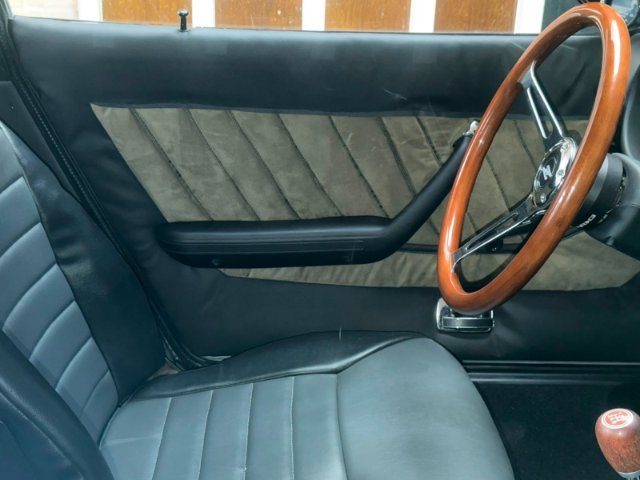
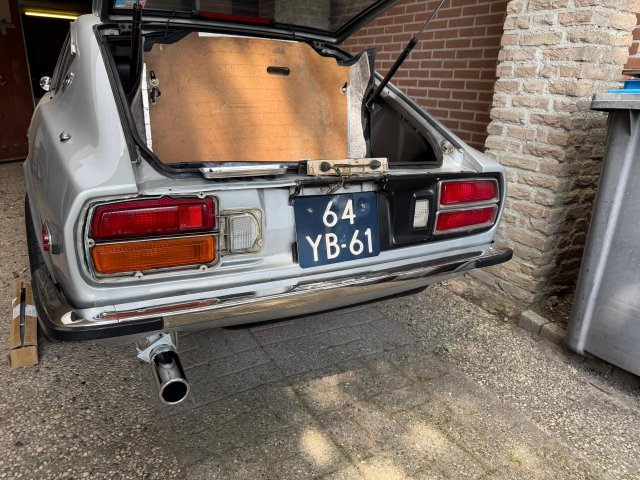
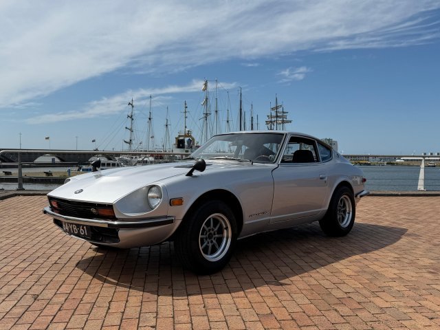
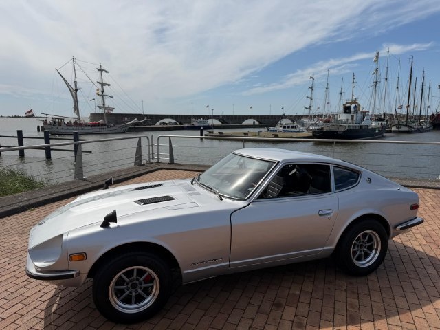
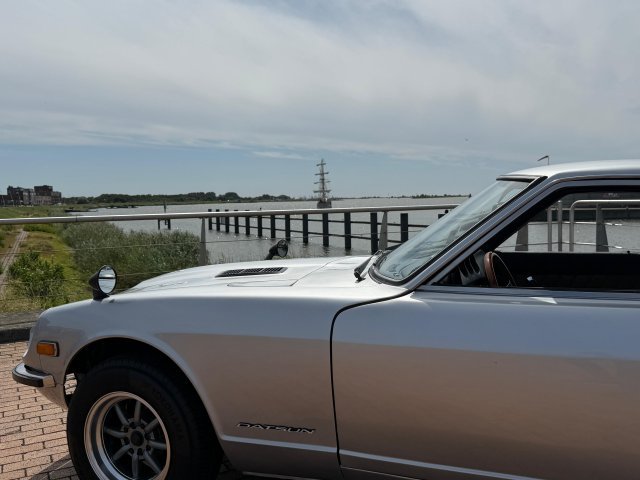
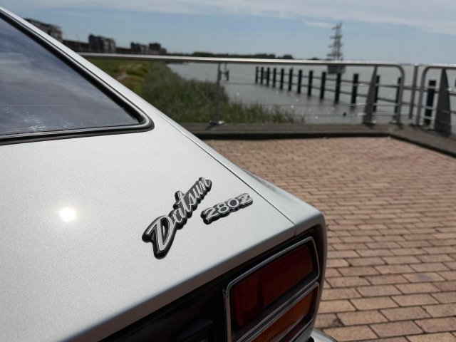
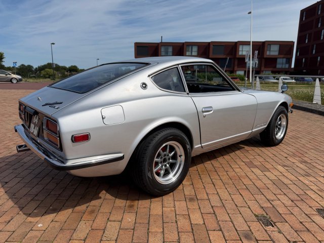
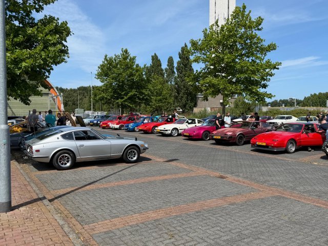
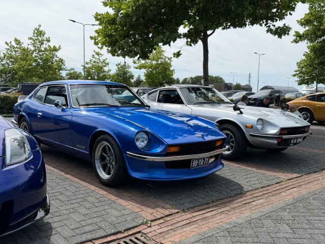
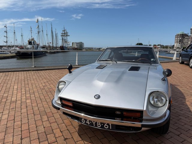
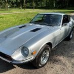
I finally had some time this weekend to work on the Z again and finish off some of the little things that where nagging me. I finished my DIY door card project and got them installed in the car. I must say that they turned out pretty good. The only finishing piece would be to add the wood trim back in but I would have to make one myself. A few weeks ago I managed to pic up a set of Euro taillights from an original Dutch 260z that where in excellent condition. So with the remaining time I had that day I quickly switched them out. Yesterday there was a small all Nissan/Datsun meet I attended which gave me the opportunity to compare my Z with others and do up some inspiration for future modifications. Afterwards I finally had the time to take some proper pictures of the car (with the car not half apart) and cruise along the dikes. WhatsApp Video 2026-07-13 at 09.15.40.mp4
 3 points
 -
You want to do mine next?2 points
-
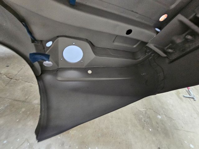
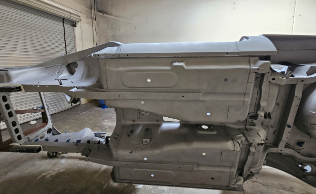
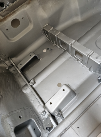
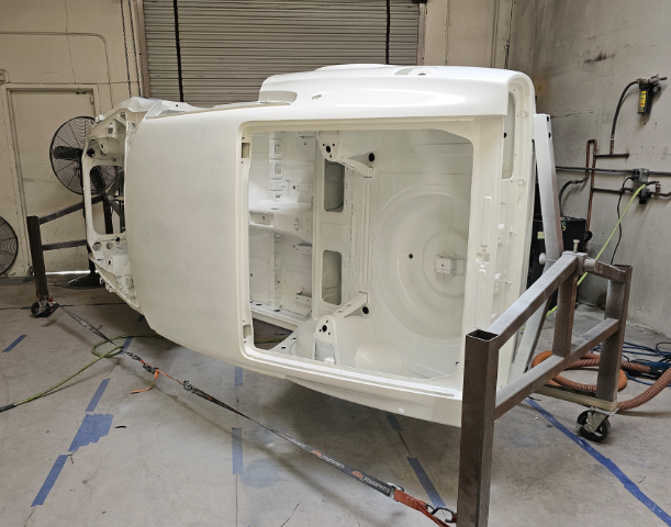
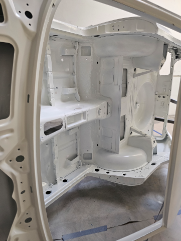
Its been an exhausting month of hard work getting the chassis in Epoxy to move it back home before the end of the month. Here is the process. 1.) strip all factory sound deadening/undercoating with a scraper, heat gun, wire brush. 2.) clean any residue with paint stripper and after-wash solvent. 3.) strip original paint from body with Citri-Strip paint stripper - again clean with after-wash 4.) remove interior tar paper with dry ice and liquid nitrogen. 5.) wash and clean entire body with Mastercoat metal prep - phosphoric acid rust neutralizer https://nomorerust.com/collections/metal-prep-rust-remover-products 6.) sandblast all seams and overlop joints. 7.) brush Mastercoat rust sealer primer into all seams and nooks https://nomorerust.com/products/mastercoat-ultimate-permanent-rust-sealer-silver-primer-original-sprayable-slim-quart 8.) lightly blast the floor pans with white aluminum oxide until white metal 9) brush 3 coats of Mastercoat rust sealer primer on to floors 10) blast the internal frame chambers clean and blow out any sand 11) spray the internal cavities ( rocker panels, rear fenders, rear internal quarter, and front internal cowl area with Matercoat using a 18 inch long extended tip spray gun https://paascheairbrush.com/collections/extension-spray-guns?shop_consented_scopes=email%3Averified+openid+pay%3Asession_token+profile+shop%3Aaccount_uuid&shop_sign_in=true using a 360 degree spray tip to coat all surfaces 12) sand the entire body removing any Mastercoat not reaming in pits or detents 13) sand the entire external body shell and underside with 180 grit and clean with wax and grease remover 14) lightly blast entire body inside and out until perfectly clean and lightly textured to promote adheision - holding the blast nozzle 12 to 15 inches away at 60psi with white aluminum oxide 15) hours blowing out the remaining grit 16) again using 360 degree long extension spray gun, paint all internal cavities and under sides with DPLV Epoxy Primer 17) Spray entire body inside, outside, underside with 2 coats of Epoxy Ridiculous amount of hours https://www.youtube.com/watch?v=y-kogRrJYJU
2 points
-
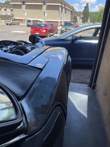
Got a little more work done. Started getting the front end together. headlights wired up. have new corner markers on the way and need to come up with a grill and turn signal. Bent up some brake line templates and headed to the parts store to try and get some pre bent heater hose. was a successful journey. got a u bend that worked for both hoses perfectly. Got the hoses on. pressure tested for leaks. found one small one at the turbo. fixed it. filled and bled the cooling system. Got the fan hooked up to the ECU thru PWM, and man does this fan flow some air. turned all the way up it might move the car like a fan boat. haha. I had it running while playing with the tune at 35% duty cycle and it CLT stayed at 172ºF when it was 85ºF in the shop so i was happy about that. will play with setting once i can get it on the road. I made the alternator bracket to move it to the driver side but having a little issue with belt routing. Currently did get a belt on but the tensioner doesn't have enough movement to work how I'd like so I'll reevaluate this later. Belt is tight and spins everything so I can run it this way for now and figure something else out later. I have the same alternator on my other car but on the passenger side so worst case I can probably get away with moving it back over there. just was trying to avoid the heat from the turbo. Also got the brakes bled. I'm real close to taking it for a spin around the neighborhood. Going to try and get the edged around the windows sanded and buffed this week so i can put the glass back in.
2 points
-
can't believe its been almost a month since an update. got the exhaust done, made a tip from stainless. Got the wastegate tube recirculated, header and downpipe wrapped. Have been wiring away. Running an ecumaster emublack ecu and a hardwire electronics PDM25. Both of which are new to me. Got the engine harness done and chassis harness started. thinking thru everything has been a challenge but so far so good. Have the PDM powering all the lights and the ECU functions. Have the factory blinker stalk controlling the blinkers, and high beam functions. Factory brake pedal sensor for brake lights and Blink marine 12 button can keypad controlling some other functions. A couple days ago i did get it to start and that was a huge relief after this long process and "freshish" engine. oil pressure is great. engine is quiet. so very motivating. 20260707_210144.mp4
2 points
-
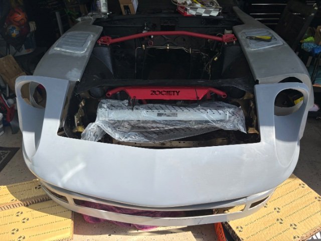
07-01-2026 ATLAS Z UPDATE: Well in between working on my other Z, I am still working on this Z car. I went ahead and started working on getting the blue painted portions of the body ready for clear coating, and caulking the border of the carbon fiber pieces. Initially I had planned to paint on a fresh coat of factory blue before clear, but I think I may go with the patina finish that is left after smoothing out the paint and getting it ready for the next step. Using "Poppy's Patina" in a high gloss finish....2 coats.....apply and then the next day apply again for 2 coats is the plan for now. This car is meant to just have fun with. It's the project car while I have the other Z anyway. my 240Z is giving me some timing issues to contend with so I have plenty to do. Also put my water meth pump on some steel to start getting the ideas flowing. PICS:
2 points
-
For me it works more often, and when it does work it's very snappy. When it's slow, I just hit refresh and go to a different tab for a moment and it'll be back by the time I return. It's still not perfect, but I think it's better than it was.1 point
-
I think "exhausting month of hardwork" is an understatement. Great job. starting with a fresh slate is so nice but so much work.1 point
-
1 point
-
I haven't noticed much difference but i generally refresh the page and then flip off it and do something else while it loads.1 point
-
260Z Seatbelt Interlock & Starter Circuit Troubleshooting I’m working through a starter‑circuit issue on my early 260Z and wanted to document everything I’ve done so far to bypass the seatbelt interlock system. I’ve followed the factory service bulletin step‑by‑step, but I’m still running into problems and hoping the electrical experts here can help me figure out what I’m missing. What I’ve Done So Far (Following the Nissan Service Bulletin) Nissan • Disconnected the seatbelt control module under the dash Removed all three harness plugs from the module. • Unplugged and removed the wiring distribution block on the firewall This is the multi‑connector block tied into the interlock logic. • Removed the red reset button on the passenger fender Pulled both connectors and jumped the Black/Yellow (start signal) to the Yellow (starter output) per the bulletin. Result: Even with the entire interlock system removed and bypassed, I still hear a click under the passenger‑side dash when turning the key. Also, when trying to start, the starter solenoid spins but the starter doesn’t engage. Second Approach: Installed a 4‑Prong Starter Relay Since the jumper bypass didn’t solve it, I tried a more direct method: • Removed the jumper at the reset switch. • Installed a 4‑prong relay on the firewall. • Wired it as follows:• Pin 30: Direct feed from the battery positive. • Pin 85: Trigger wire tapped from the Black/Yellow ignition START wire just below the ignition switch plug. Clean start signal. • Pin 87: Dedicated wire straight to the starter solenoid spade. • Pin 86: Grounded to the firewall. Result: The car does crank with the direct battery feed. But a new issue appeared: When I turn the key back to ON after START, the starter continues to crank nonstop. The only way to stop it is to disconnect the battery cable. I tried a relay with a resistor thinking the solenoid might be back‑feeding the relay coil, but the problem persists. --- Where I’m Stuck I’m not an electronics expert on the 260Z, but I’ve done plenty of wiring work on 60’s cars. I’ve searched all over the web and found bits and pieces of info, but nothing that fully explains what’s happening here. Autos& Vehicles At this point I’ve: • Removed the entire seatbelt interlock system • Bypassed the START circuit per the bulletin • Tried a modern relay setup • Still have a mystery click under the dash • And now have a starter backfeed issue where the relay won’t release I’m clearly missing something in the early‑260Z wiring logic, possibly a hidden splice or secondary circuit feeding the START wire. I’m reaching out to the experts here who have more experience with these cars. Any guidance, diagrams, or known trouble spots would be greatly appreciated. I’m stumped and would love to get this resolved. Thanks in advance for any help.1 point
-
It's a "little" thing, but progress.
1 point
-
07-19-2026 ATLAS Z UPDATE: I started by color sanding and buffing the tops of the fenders and the sail panels with 2000 grit, 3000 grit and 5000 grit and then used Meguires Premium Polish with my foam pad on the buffer at medium speed. Then I re-installed the side view mirrors, and re-installed the emblems and plug for the antenna hole. Then I finished the door panels by putting the latch surround trim under the door release latches on both sides. Then I took some rope and measured out the length for the serpentine belt and the remaining brake lines, which will also be PTFE braided line form "Finishing Lines". All of this took longer than it sounds. PICS:
1 point
-
You really need the hard ring to make it work. The rubber cover holds it in place, but the plastic or metal ring is the pivot, so the geometry is right, and the cable can pull the brakes and hold the car.1 point
-
I'm not dead. 2025 was a pretty big bust though. Just way too much going on being a family man. But I've recently made some progress. Engine is back out for hopefully the final time. Finished welding up the chassis side of the engine mounts and engine bay is painted. Still need to do some finish welding in the transmission tunnel. Also fabricated a mounting bracket for the brake master (booster delete). Still to be done off the top of my head: Cut down and weld the brake master pushrod Fab new brake lines Mount clutch master Fab clutch line Install flywheel Install adapter plate for final time with loctite and such Install clutch Drain and replace fluid in transmission Clean up transmission shifter hole (rusty from standing water in it (before me)) Install transmission Install new thermostat housing Install rear coolant adapter (with gasket, was just set on for test fitting) Install intake coolant adapter Fab and install engine to engine coolant lines Finish last bits of engine harness wiring Weigh final engine/transmission combo Install engine/trans for (hopefully) last time Fabricate radiator mount and ducting Mount and plumb radiator Plumb fuel line That's starting to get down into the last bits before first fire up. I'll also need to fabricate exhaust at some point, but it'll survive running an open header for just getting it back on the ground. With any luck I hope to have it close to first start by end of August. Will depend on how many side quests I have to also complete.1 point
-
Note that this applies to my 1972 V8 240z which uses a Motor Sports Auto (MSA) / Jags That Run (JTR) style hood release bracket. The stock hood release cable tends to fail with age. If the cable breaks you will be very sad. So I decided to replace my failing hood release cable with a Lokar Hood Release Cable kit. I installed the hood release handle where the driver’s side vent control was mounted. The vent control mounting bracket is rigid and lines up the hood release cable with the stock hole in the firewall. The vent control was moved to the left of the Lokar hood release lever and bolted to the underside of the dash. Installation required making two brackets from 2” x 2” x 1/8” aluminum angle one for each end of the cable. The release arm on the stock hood latch release mechanism required modification because the Lokar cable stop would not fit into the stock cable connection. I removed the stock cable connector on the release arm and replaced it with a spare Lokar throttle cable end and ball pivot. This allows the attachment point on the lever arm to swivel as the release arm moves to release the hood latch. Summit p/n: Lokar Hood Release Cable Kits HR-1100U $129.95 https://www.summitracing.com/parts/lok-hr1100u Summit p/n: Lokar Cable Fittings WCA-1034 $33.95 https://www.summitracing.com/parts/lok-wca-1034
1 point
-
Good post! I love the annotated pictures.1 point
-
Replacement Door Mirrors for a 1972 240z Nissan The old MSA door mirrors fell apart and I wanted to find a better replacement. After doing some research I found that GM part #987460 refers to the classic chrome outside rearview door mirror used on 1955, 1956, and 1957 Chevrolet passenger cars would be a good fit. I found a kit that provides both left and right mirrors at United Pacific: Item No.110745 Exterior Mirror Bundle for 1955-1957 Chevy Passenger Car (Pair) which includes: · Polished stainless steel mirror head & chrome plated arm with identical design as original. · Convex mirror with wide angle optics for R/H side. https://classic.upauto.com/exterior-mirror-bundle-for-1955-1957-chevy-passenger-car-pair-110745 I purchased the mirror kit at Amazon for $57.69 https://www.amazon.com/United-Pacific-110745-Exterior-Passenger/dp/B07CSM82R6/ref=sr_1_5?crid=3D4VKZQDPPL45&dib=eyJ2IjoiMSJ9.Ji_ewCdOZDHJk5NTl-hJJNFlKNsQBt5lpAOLKHcRoK31x-GRce_gxezK_VKJFo0J9IkZHkDcZBC1uO-yqa9wAikFa3d3ppFs1Z_e9oMH7GHS0hSYXVCL3mPH2KdHlNipyinC19rlSI2bJ2OSt4dOu31VkbQgttxV3F9sjOnvlwdEzUBrH0x35XHZypqXaZKhHaGVoA8HQfe6yph6tpYjD9i1U7980UgA3v1My4M_ZeA.60nOt1lFZGTfNCnWtHJyTgcmFLSL1-4Gz3NCXbznMr0&dib_tag=se&keywords=car+side+mirrors+chrome+metal&qid=1783662323&sprefix=car+side+mirrors+chrome+metal%2Caps%2C189&sr=8-5&ufe=app_do%3Aamzn1.fos.9fe8cbfa-bf43-43d1-a707-3f4e65a4b666 See pictures.
1 point
-
Your engine bay looks very clean, nicely done! You really are flying true this project, keep up the good work!1 point
-
I can’t wait how she looks out in the sun!1 point
-
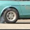
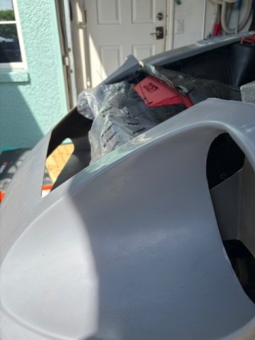
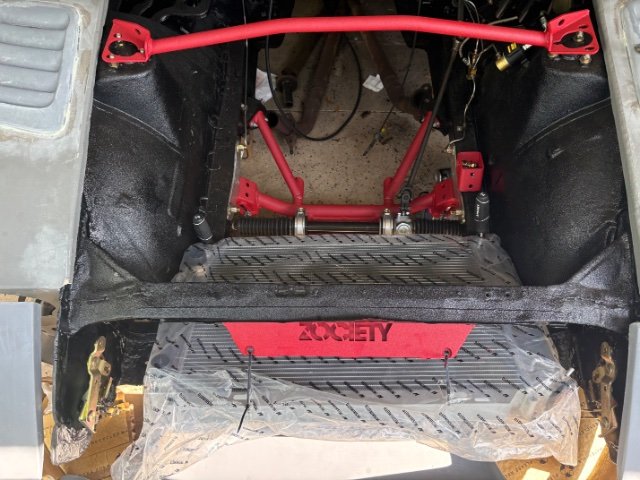
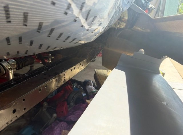
Radiator came in, made a mistake on sizing it, but I think it still works just fine sitting on the frame rails, thoughts? Or should it get something skinnier that fits between the frame rails. I like the built in tray on this bumper, I’ll add some ducting that just continues this on to that bottom rail and continue it past to the end of the radiator.
1 point
-
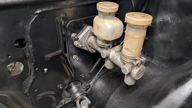
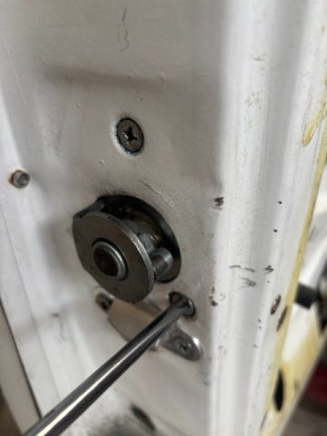
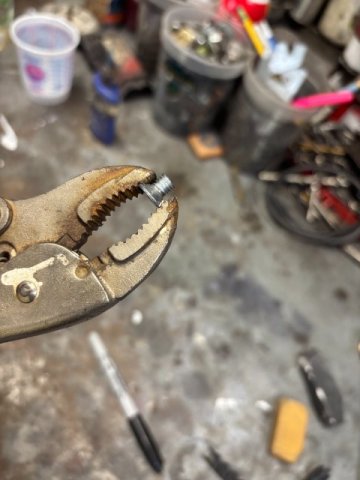
A simple solution for door slamming problem? I finally finished my 8.8 Super Duty 8.8 Differential Conversion so I had time to handle all those small detail work. During my restoration work, I used Precision Weather Stripping to my worn OEM ones. But the Precision Weather Stripping always seemed too stiff for its job. So anyway, I gave them about 4 months but still had to slam the door to seat the weather stripping. It never got better so I know some members used late model KIA weather stripping from Amazon and good results. So I tried the Kia weather stripping. It was a lot softer but still had to slam the door. I decided to remove the Door Latch and study its operation. After removing it, I cleaned it and lubricated it with White Grease. Everthing seemed tested fine when it was out of the car. But after installation, the problem was still there. The Door Latch seemed like it still needed a little more inward movement to function properly. So with the Door Latch installed, I watched the Locking Mechanism operation. As the Door Glass was not installed yet, you have a good view of the Locking operation. this is when I noticed that one of the Latch Mounting Phillips Screws( 6mm x 1.0) was hitting the Linkage. This Screw is 4MM too long. The Easy Solution was to cut off about 4MM of the threaded end of the screw. Pic of the Long Phillips Screw-Inner Bottom Mounting Latch one. ". , Pic of "Corrected Phillips Screw" I really don't know when the Phillips Screw was mistakenly replaced with a Longer One. Owning the 240Z for 54 years, I am sure I removed the Door Latch at least 4 times. Anyway, if you are having Door Slamming Problems, check the LATCH MOUNTING SCREWS. It was a Simple Solution for me, maybe for you, too.
1 point
-
Have you verified your engine is actually at TDC? Your damper or timing marks could easily be off a few degrees. Enough to give you the results you're seeing. Verify TDC with a piece of aluminum rod or a piston stop in the #1 plug and then go from there.1 point
-
I still get a site not responding when I go to it and have to wait more than 30 seconds for it to load. Clicking among sub forums takes a while as does loading threads. Whatever he's doing isn't working ..0 points
-
@senna21 I would advise you (if you still have a chance now) to remove your brand new sending unit and apply some JB Water Weld or Tank Weld (or whichever preferred fuel resistant epoxy) to the inside/outside of those terminal posts. My brand new sending unit from ZCar Depot leaked. I filled up my brand new tank (also from the s30.world) and went to a car show. I had a big embarrassing fuel leak. They are sending me a replacement unit. I won't be taking any chances again and will JB weld stuff. Both posts leaked.0 points