Leaderboard


Popular Content
Showing content with the highest reputation since 02/12/26 in Posts
-
Since that broken rear differential a lot has happened.
 4 points
 -
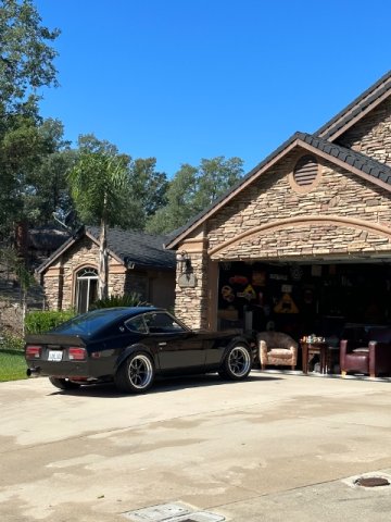
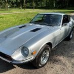
I have been here for long rime, just not lately. I have a nice 83 280ZX Turbo. Which started me on this site. I just modified ,restored a 71 240Z. Both are 5 speeds. I love them both.2 points
-
My toy house 71 240, 83 280ZX turbo and my built 78 El CaminoSS.
2 points
-
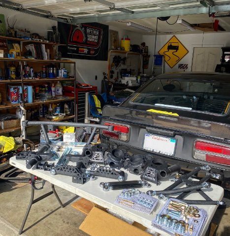
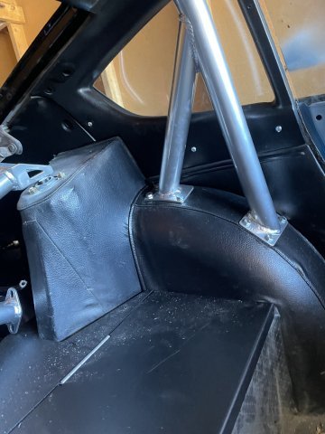
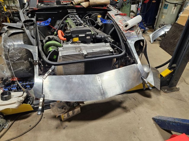
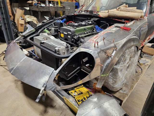
Unrelated update but reasons as to why there's been a lack of updates to this thread: Got a new job that demands a lot more of my time so unfortunately less time to optimize the SLA conversion. Upside however is that I'm learning NX which seems to be some next level software. I think this design is going to take one more fundamental change to really get the dynamic geometries perfect but the work I have so far has been a pretty excellent starting point. The car is also back from the rust repair shop and the cage shop, needless to say my wallet is in a lot of pain at the moment (especially with the S54 being built) but we do these things not because they are easy but because they are hard and we hate money. Anyway, enjoy some photos of the cage in the meantime.
2 points
-
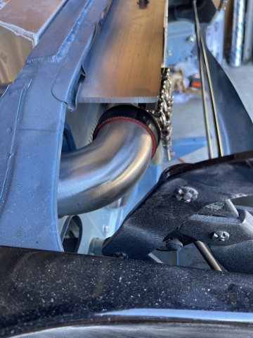
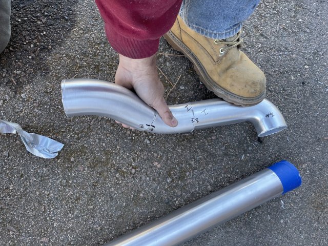
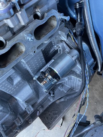
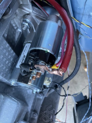
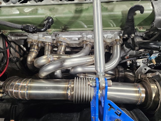
03-07-2026. ATLAS Z UPDATE: I started with the intercooler piping on the turbo side, and have it ready for welding, sanding and polishing. I got started on the intake side, but ran out of parts. Since I had to pull the intake, I enjoyed the easy access to that side of the engine, and installed my new AC Delco starter, and wired the solenoid and main batt power on it. I also was able to plug in the harness points on that side of the engine, install the crank position sensor and both knock sensors, all new GM stuff. Started on the alternator bracket modifying, much more on that to do. Feel got cold, called it a day. PICS
2 points
-
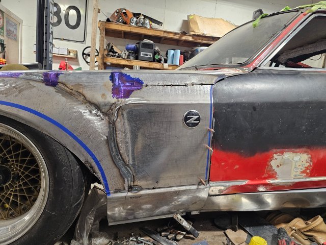
Looking GREAT!! 👍👍 I really like the metalwork....makes you look like a skilled Italian craftsman (whereas mine makes me look like a one-armed monkey with a rock and a baseball bat.)2 points
-
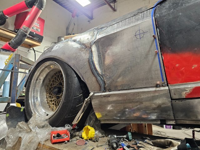
this has to be one of the slowest builds....small update.
2 points
-
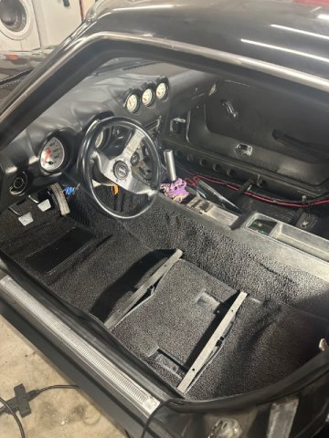
Dash cap is on! next is gauges and center section install. run the wires so once installed the wires are right there and can be easily wired. Speedo is GPS. Speedhut gauges. Made in USA, cost is like sending a kid to college
2 points
-
What will be the main purpose of the car for you? What do you want the car to be? Seeing as you will be installing a roll gage, iMSA widebody kit and an LS big block for I suspect power and torque, you will mainly track the car and won’t be driving on the road. I like your choice of Apex over T3 but that’s my personal preference. But why the Pro Touring and not the Track Attack kit? Also don’t forget the basics of the build like chassis reinforcement, safety features and fuel delivery. These chassis are over 50 years old so if you plan to track and abuse them make sure the basics are good, rust free and reinforced. A good roll cage will do a lot together with the frame sleeves and some bolt on parts but things like seem welding the chassis will also help a lot. VA Engineering over here in the Netherlands has some great pictures on their Instagram of their cages and seem welds. The transform the S30 Z’s into period correct rally cars and yes they do get used like a rally car should.1 point
-
THANK YOU Sir. I am really enjoying this car.1 point
-
Yes, the front strut tower reinforcement is connected thru the firewall. Attached is a photo that kinda shows it off, these are slightly old pictures taken by the welder prior to taking delivery. Cage has since been finished and had gussets added to the A-pillars. The fender braces from Apex are located inside the front fender outside of the driver cabin. I also have them, not sure if I'll end up using them, cage installer wasn't convinced they really do much other than maybe preventing the front wheels from coming into the cabin during a head-on collision. Plinth location is the deciding factor in how your door bars and subsequent firewall > strut tower bars will/won't interfere with your pedal box. My door bars are pushing right to the outer edge of footwell and angle up from the bottom of the A pillar bar to fit my left if needed. Not sure what pedals you're using but I have a Tilton triple master setup that's going in so the world is my oyster so to speak in terms of pedal placement. This dude's pedal setup looks super neato and I would like to replicate the adjustment mechanism.
1 point
-
Hey Dave, did you have any luck getting a driveshaft done? I had to have a custom one done here in Dallas. I’ll get you the name of the place if you still need it.1 point
-
do you have a photo of how the front strut tower bar goes thru the driver side firewall? I'm in the process of finishing up my cage and was considering running a few bars thru the firewall like yours but the driver side has more stuff (clutch master/pedal) in the way for a straight shot. I don't know how tall you are but i stayed just in front of the wheel well for the main hoop and its definitely a bit tight for seat position so up on the rear tube will be helpful for that.1 point
-
You are flying true this! Love to see your progress!1 point
-
03-08-2026 ATLAS Z UPDATE: I got the rollbar in, a little interior painting around those areas, and then I cut the thick steel plates for my "cross bar" section going on the floor from the door jamb right in front of the seats, over the tunnel down the other side and to the other door jamb. Ready for the welder! I also did a little bit of interior parts painting, but the floor plates took quite a awhile. PICS:
1 point
-
Yeah, good point. It's a new feature we're trying out. We're still working out the kinks; so I apologize in advance if you're receiving duplicate notifications. Thanks for the feedback!1 point
-
I liked the email reminder! I think annually would be sufficient.1 point
-
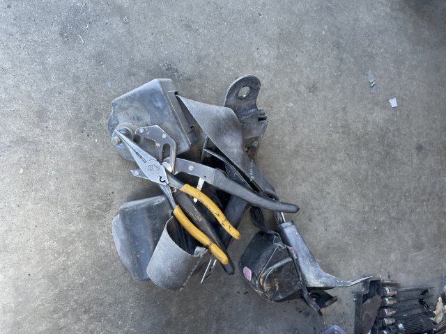
03-06-2026 ATLAZ Z UPDATE. Well, today was Seat Belt Day! When the tub and walls need a cleaning, you go ahead and grab your 52 year old belts, some pliers and duct tape to hold them extended and grab a heavy duty brush, some dish washing detergent and get to it! The water going down the drain was a dark brown soup. Dirt, dust, skin, body oils, everything. You know they never get cleaned. Once dry I will have to paint the housing with the SEM Interior paint, but they will be nice. Oh and the tub is all clean and disinfected with Pine Sol! PICS:
1 point
-
I know how to close the ads 😄. And I don't expect entirely ad free. I do as a user don't want 80% ads though. And agreed there is cost involved, not doubting any of that. There is no such thing as a free lunch as they say. Guess we are all constant problem solvers 🤔. My only thought isn't so much from a how do I block ads, but I know hybridz gets referenced all the time on Facebook groups and Reddit. If I was a new user and didn't happen to have adblock setup, I definitely wouldn't sign up because nothing looked legit. My .02, appreciate y'all listening and I'll go back to my own problems 🤣1 point
-
Tap the arrow on the drop down ad and it will collapse. Then just scroll down. I too lament how prevalent ads are on the internet these days, but Dan has to pay for the server somehow. I like the membership idea. The merch campaigns always bring in a ton of money, but that takes a lot of work from whoever is organizing it.1 point
-
This whole forum seems abandoned...
1 point
-
Thanks jhm — appreciate the honest response, and totally understand the bind. Obviously, I'm shooting in the dark here. I don't know the traffic, active users, new users etc. Firstly: you are correct, ad block exists. I could do something like that for mobile too just like desktop versions. Out of curiosity, has there ever been any thought toward a paid ad-free tier? Honestly, if it was under $5-10 a month I'd sign up today, I pay $9 a month to Skooler.com, I've used it once, but have never bothered to cancel the membership. Feels like there might be others who'd rather pay a small amount than fight the ads, not a one time donation, but an a subscription and a badge. Are the ads currently through something like AdSense, or do you have any direct vendor relationships? I can't help but notice a Ford Mustang dealership ad on a 280ZX forum and wonder if there's a more Z-relevant way to fill that space. Not trying to armchair quarterback, just genuinely want to see this place thrive. Self Acknowledgment: these things could have been tried during my time away and that is on me.1 point
-
1 point
-
I just posted this to ZCAR: “Receiving periodic/automatic emails that say: ‘Come back, we’ve missed you!’ Sometimes life gets busy enough that I forget to login. I appreciate getting occasional emails reminding me of this great resource. I also think it helps keep the involvement up in the forum. Excellent idea. Thank you.”1 point
-
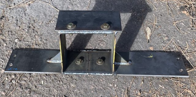
02-26-2026 ATLAS Z UPDATE: Today I got my rollbar and rear strut brace back from the powdercoater as well as the tunnel I dropped off to sandblast. The rubber is still on there, but this yucky sticky layer of honey look goos (glue) is gone. I also picked up my trans mount, he welded it up and added gussets on both sides out of 1/4" plate. I painted the back side quickly before I ran out of paint. Ready for the next day in the garage! P.S. self tapping screws and sheet metal (18 ga) here and ready to built it back, then the welder will stitch weld it and weld the plates over the top and over on both sides to the door jambs. 1/4" thick, 4 inch wide plate. Car will be overbuilt int his area like I did with the radiator support. 350-400 horsepower you really have to, even with the reinforced floor I have.
1 point
-
this is very cool, I will be following along. Love the custom work. I am doing a 1jz swap myself at the moment so nice to see another with another person fab ideas1 point
-
turbo manifold is welded up and installed. I forgot to take pictures before it went in
1 point
-
😅 hopefully the only thing looking this good is the front. Ill leave the rest looking abit rougher. Really wanting to pull it out this year and at least drive around the block1 point
-
02-18-2026 ATLAS Z UPDATE: picked up my 1/4" thick steel plate for making the transmission mount, set out my seat belts for cleaning, and my rear strut tower brace from Apex and a Autopower Street rollbar from Motorsport Auto have arrived. So, I will decide what color I want to powdercoat stuff (gloss black of "polished aluminum") , and keep pressing forward. Will be COLD for a few days, so any work done will be indoor stuff. PICS:
1 point
-
8th build? Wow! I'm still nursing my first (and only). Car has been on the road, and off. Registered, and not. The current iteration is "not". I need help - local help - with the care and feeding of the engine. The real problem isn't with the Datsun parts, but the Chevy parts... namely getting that darned engine to work properly. Seems like a simple problem, no? But nothing is simple these days! Also, the exhaust is too loud, and the transmission is geared wrongly. I need a custom re-welding for the former, and to write a check for the latter. I also need an engine hoist and a place to work on the car. Success with hobby-cars, begins with success in real estate!1 point
-
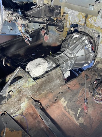
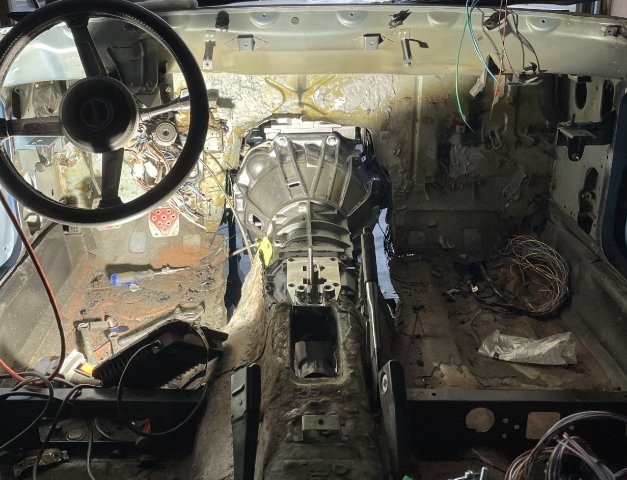
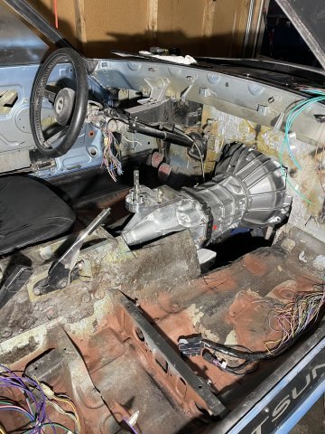
02-14-2026 Happy Valentines Day! Today I got the transmission in. Took a long time. I left the pilot bearing in the freezer overnight, and I was able to tap it in easy. After I installed the clutch and made sure to use the ARP lube on the bolts, I started prepping the trans tunnel. I had to cut off the factory trans ears and grind them smooth and gave them a quick coat of paint. Then the hard part started. After trying and trying, I realized the trans tunnel just wasn't going to let it happen.....so I started cutting it out from the firewall back about a foot or so, then more and more..... little at a time, as I needed the room. I did keep the pieces cut out, As I will cut and modify and have a mobile welder come and weld them back in AND while here weld a thick steel flat plate about 3-4 inches wide the trans area and passenger floors to add more reinforcement for the power level of the engine. I was able to use a floor jack and level the engine up, and now you can see in some of the pics, what it looks like level.....yeah, dusty but you can still see it. My center console will be modded with the center floor cut out leaving a small ledge on both sides so I can make a custom aluminum floor. The shifter mechanism will be left fully exposed, I love look. It makes the shifter throws SO SHORT! So, big day. All in, now need a trans mount underneath that will bolt through the floor into plates to hold it, the reinforcement plates across, and eventual console mod. I got VERY dirty! Cheers! PICS:
1 point
-
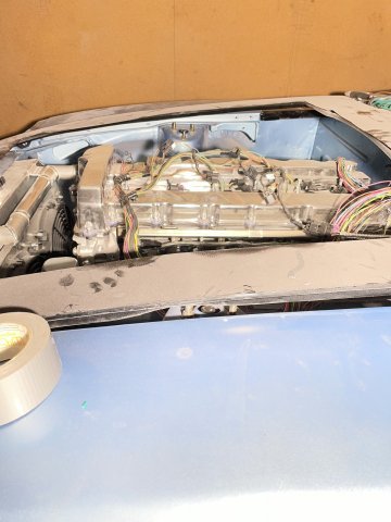
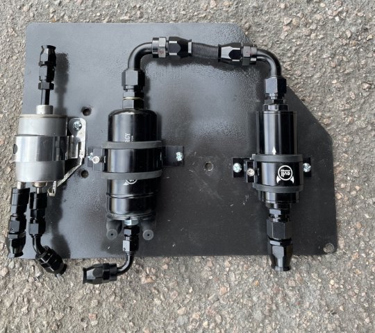
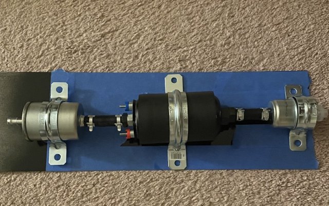
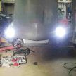
02-11-2026 ATLAS Z update: I got back half of the car all wired in except for a license plate light I am waiting for it to arrive. pretty cool LED unit I found on Amazon for 8 bucks. Got the headlights almost in. I always have a problem with this job. I had to break out the angle grinder and mod to get the driver's in....unsure so far far with the passenger one. Strange..... it REALLY fought me. I also got the 10AN line between my main filter and pump in, so it is ready for installation. PTFE lines take some work.
1 point
-
Thank you. a bit overkill but im happy with how it came out. I hadn't planned on making them but no reason i can't. I can get some material and when i get some down time i could make another one.1 point
-
up here in the north east we get some great fall scenery for cruising but can get a bit chilly so the heater will be used for that aswell. but the defroster on a raining track day will be important. Thank you. love being creative during a build.1 point
-
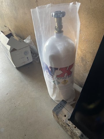
08-15-2025. Again, more parts arriving and I got a piece of 16 ga. steel painted up and then assembled my fuel pump and filters and laid it out and marked for drilling.
1 point
-
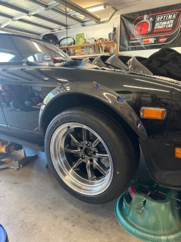
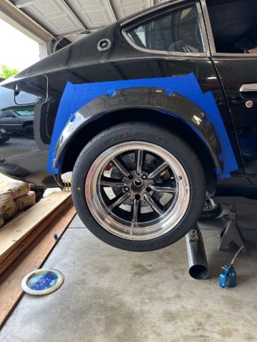
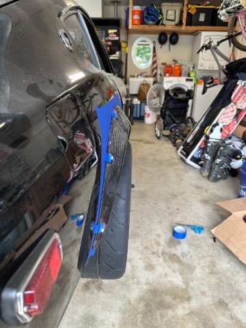
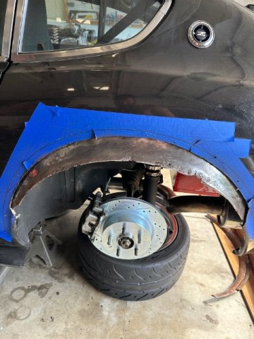
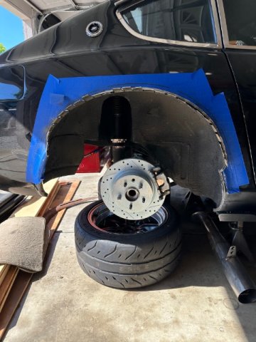
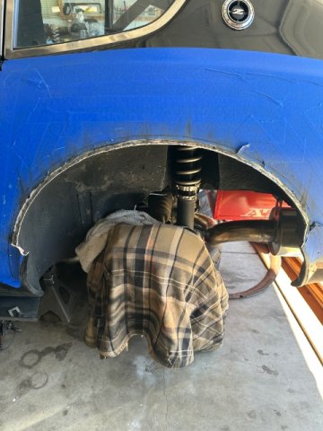
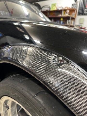
Slowly making progress Fender revised and partially welded Turn signal mounted
1 point
-
1 point
-
FWIW, I have a ZTrix hood on my 2X Nat Champ EP car. It weights 10 lbs and was weighed with an accurate scale. I asked John Washington to lay this up with weight in mind. The hood is sufficiently stiff and doesn't have any CF in it. It's pretty surprising really. I bought some more of these recently with John and they weighed 13.5 lbs. I assume this hood would work properly with the front torsion mechanism on the stock Z, but we don't use that or the rear latch. Hope this helps. Greg Ira1 point